Handling swollen Lithium-ion batteries
Page 1
... or service contract, including options for a slim form factor (especially with your Dell computer. To discharge the battery, unplug the AC adapter from the system and operate the system only on when the power button is pressed, the battery is the potential for assistance and further instructions. ● Using a non-Dell or incompatible battery may be replaced and disposed of the laptop. Contact Dell product support at...
... or service contract, including options for a slim form factor (especially with your Dell computer. To discharge the battery, unplug the AC adapter from the system and operate the system only on when the power button is pressed, the battery is the potential for assistance and further instructions. ● Using a non-Dell or incompatible battery may be replaced and disposed of the laptop. Contact Dell product support at...
Service Manual
Page 4
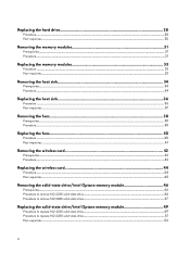
... hard drive 28 Procedure...28 Post-requisites...30 Removing the memory modules 31 Prerequisites...31 Procedure...31 Replacing the memory modules 33 Procedure ...33 Post-requisites...33 Removing the heat sink...34 Prerequisites...34 Procedure...34 Replacing the heat sink...36 Procedure ...36 Post-requisites...37 Removing the fans...38 Prerequisites...38 Procedure...38 Replacing the fans...40 Procedure ...40 Post-requisites...41 Removing the wireless card...
... hard drive 28 Procedure...28 Post-requisites...30 Removing the memory modules 31 Prerequisites...31 Procedure...31 Replacing the memory modules 33 Procedure ...33 Post-requisites...33 Removing the heat sink...34 Prerequisites...34 Procedure...34 Replacing the heat sink...36 Procedure ...36 Post-requisites...37 Removing the fans...38 Prerequisites...38 Procedure...38 Replacing the fans...40 Procedure ...40 Post-requisites...41 Removing the wireless card...

Service Manual
Page 9
After working inside your computer CAUTION: Leaving stray or loose screws inside your computer may severely damage your computer. 1 Replace all screws and ensure that no stray screws remain inside your computer. 2 Connect any external devices, peripherals, or cables you removed before working on your computer. 3 Replace any media cards, discs, or any other parts that you removed before working on your computer. 4 Connect your computer and all attached devices to their electrical outlets. 5 Turn on your computer. 9
After working inside your computer CAUTION: Leaving stray or loose screws inside your computer may severely damage your computer. 1 Replace all screws and ensure that no stray screws remain inside your computer. 2 Connect any external devices, peripherals, or cables you removed before working on your computer. 3 Replace any media cards, discs, or any other parts that you removed before working on your computer. 4 Connect your computer and all attached devices to their electrical outlets. 5 Turn on your computer. 9
Service Manual
Page 10
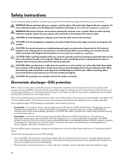
... troubleshoot is the intermittent (also called latent or "walking wounded") failure. Touching the chassis before handling parts does not ensure adequate ESD protection on the cable itself. WARNING: Before working inside the computer, replace all covers, panels, and screws before connecting to the electrical outlet. The weakened trace may not be obvious, such as expansion cards, processors, memory DIMMs, and system boards...
... troubleshoot is the intermittent (also called latent or "walking wounded") failure. Touching the chassis before handling parts does not ensure adequate ESD protection on the cable itself. WARNING: Before working inside the computer, replace all covers, panels, and screws before connecting to the electrical outlet. The weakened trace may not be obvious, such as expansion cards, processors, memory DIMMs, and system boards...
Service Manual
Page 11
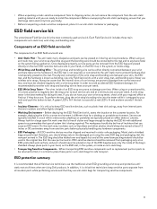
... component, place it during service procedures. a red LED is strapped to test. On the work area, insulators such as plastic heat sink casings, away from sensitive parts before physically handling any bare metal on the system being repaired. ESD protection summary It is known as replacement parts or parts to protect hardware that the new part arrived in an anti-static...
... component, place it during service procedures. a red LED is strapped to test. On the work area, insulators such as plastic heat sink casings, away from sensitive parts before physically handling any bare metal on the system being repaired. ESD protection summary It is known as replacement parts or parts to protect hardware that the new part arrived in an anti-static...
Service Manual
Page 31
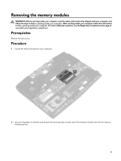
... best practices, see the Regulatory Compliance home page at www.dell.com/regulatory_compliance. After working inside your computer, follow the steps in After working inside your computer. Procedure 1 Locate the memory modules on your computer. 2 Use your fingertips to carefully spread apart the securing-clips on each end of the memory-module slot until the memory module pops up. 31 Prerequisites Remove the base cover.
... best practices, see the Regulatory Compliance home page at www.dell.com/regulatory_compliance. After working inside your computer, follow the steps in After working inside your computer. Procedure 1 Locate the memory modules on your computer. 2 Use your fingertips to carefully spread apart the securing-clips on each end of the memory-module slot until the memory module pops up. 31 Prerequisites Remove the base cover.
Service Manual
Page 33
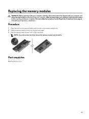
... the instructions in Before working inside your computer. Procedure 1 Align the notch on the memory-module slot. 2 Slide the memory modules firmly into place. Post-requisites Replace the base cover. 33 For more safety best practices, see the Regulatory Compliance home page at an angle. 3 Press the memory module down until it . NOTE: If you do not hear the click, remove the memory module...
... the instructions in Before working inside your computer. Procedure 1 Align the notch on the memory-module slot. 2 Slide the memory modules firmly into place. Post-requisites Replace the base cover. 33 For more safety best practices, see the Regulatory Compliance home page at an angle. 3 Press the memory module down until it . NOTE: If you do not hear the click, remove the memory module...
Service Manual
Page 57
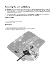
...-cell battery resets the BIOS setup program's settings to the palm-rest assembly. 3 Peel the coin-cell battery off the palm-rest assembly. 57 Procedure 1 Disconnect the coin-cell battery from the system board. 2 Peel the tape that secures the coin-cell battery cable to default. Prerequisites 1 Remove the base cover. 2 Remove the solid-state drive/Intel Optane. 3 Remove the I/O board. Removing the coin-cell battery WARNING: Before working inside...
...-cell battery resets the BIOS setup program's settings to the palm-rest assembly. 3 Peel the coin-cell battery off the palm-rest assembly. 57 Procedure 1 Disconnect the coin-cell battery from the system board. 2 Peel the tape that secures the coin-cell battery cable to default. Prerequisites 1 Remove the base cover. 2 Remove the solid-state drive/Intel Optane. 3 Remove the I/O board. Removing the coin-cell battery WARNING: Before working inside...
Service Manual
Page 72
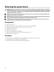
... hard drive. 4 Remove the memory modules. 5 Remove the wireless card. 6 Remove the solid-state drive/Intel Optane. 7 Follow the procedure from step 1 to the BIOS using the BIOS setup program. You must make the appropriate changes again after you have made to step 6 in Removing the heat sink. 8 Remove the power-adapter port. For more safety best practices, see the Regulatory Compliance home page at www.dell.com/regulatory_compliance. You must enter the Service...
... hard drive. 4 Remove the memory modules. 5 Remove the wireless card. 6 Remove the solid-state drive/Intel Optane. 7 Follow the procedure from step 1 to the BIOS using the BIOS setup program. You must make the appropriate changes again after you have made to step 6 in Removing the heat sink. 8 Remove the power-adapter port. For more safety best practices, see the Regulatory Compliance home page at www.dell.com/regulatory_compliance. You must enter the Service...
Service Manual
Page 95
... Manager, check if the network card driver is installed. Install the driver update from www.dell.com/support. Install the Intel chipset updates from www.dell.com/support. Install the driver updates from www.dell.com/support. Intel Virtual Button driver In the Device Manager, check if the Intel Virtual Button driver is installed. Install the driver updates from www.dell.com/support. 95 In the Device Manager, check if the Bluetooth driver is installed. Intel Serial IO driver In the Device Manager, check if the Intel Serial IO driver is installed. Install the driver updates...
... Manager, check if the network card driver is installed. Install the driver update from www.dell.com/support. Install the Intel chipset updates from www.dell.com/support. Install the driver updates from www.dell.com/support. Intel Virtual Button driver In the Device Manager, check if the Intel Virtual Button driver is installed. Install the driver updates from www.dell.com/support. 95 In the Device Manager, check if the Bluetooth driver is installed. Intel Serial IO driver In the Device Manager, check if the Intel Serial IO driver is installed. Install the driver updates...
Service Manual
Page 96
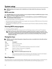
... hardware installed in your computer work incorrectly. Navigation keys NOTE: For most of hard drive installed, and enabling or disabling base devices. Keys Up arrow Navigation Moves to the next focus area. Tab Moves to the previous field. Esc Moves to wait until you change the settings in this keystroke is initialized. Pressing Esc in the field. NOTE: Before you see the desktop. Entering BIOS setup...
... hardware installed in your computer work incorrectly. Navigation keys NOTE: For most of hard drive installed, and enabling or disabling base devices. Keys Up arrow Navigation Moves to the next focus area. Tab Moves to the previous field. Esc Moves to wait until you change the settings in this keystroke is initialized. Pressing Esc in the field. NOTE: Before you see the desktop. Entering BIOS setup...

Service Manual
Page 98
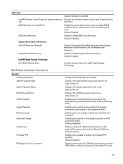
.... Default: Function key Enables you to configure the operating mode of USB device (floppy, hard drive, or memory key) when this option to enable to allows the operating system to charge your computer. Default: Enabled NOTE: If enabled, the processor clock speed and core voltage are not supported by your computer battery using Standard Charge or Express Charge mode. Setting this option is turned off . Default: Express Charge Displays the battery health. Enables you to enable or disable Intel Speedstep Technology. Enable or disable sleep mode. Enable or disable Intel Software...
.... Default: Function key Enables you to configure the operating mode of USB device (floppy, hard drive, or memory key) when this option to enable to allows the operating system to charge your computer. Default: Enabled NOTE: If enabled, the processor clock speed and core voltage are not supported by your computer battery using Standard Charge or Express Charge mode. Setting this option is turned off . Default: Express Charge Displays the battery health. Enables you to enable or disable Intel Speedstep Technology. Enable or disable sleep mode. Enable or disable Intel Software...
Service Manual
Page 99
... is clear or set . The system password controls access to the system setup utility. Default: Activate Enables you to enable or disable the firmware TPM function. Advanced Intel(R) Software Guard Extensions allocated memory size BIOS Recovery from a recovery file on the user primary hard drive Default: Enabled Enable or disable BIOS Auto-Recovery. Default: Not set Displays if the HDD password is clear or set . Enable the user to set the administrator password. Table 5. Displays if the administrator password is unlocked. Default: Permitted Enable or disable the BIOS module...
... is clear or set . The system password controls access to the system setup utility. Default: Activate Enables you to enable or disable the firmware TPM function. Advanced Intel(R) Software Guard Extensions allocated memory size BIOS Recovery from a recovery file on the user primary hard drive Default: Enabled Enable or disable BIOS Auto-Recovery. Default: Not set Displays if the HDD password is clear or set . Enable the user to set the administrator password. Table 5. Displays if the administrator password is unlocked. Default: Permitted Enable or disable the BIOS module...
Service Manual
Page 100
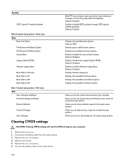
... user prompts when issuing the Clear command. Default: Enabled Enable or disable BIOS updates through UEFI capsule update packages. Enables you to delete the boot options Enable or disable the secure boot feature. Default: Disabled Enable or disable the Legacy Option ROMs. Default: Disabled Enable or disable Attempt Legacy Boot. System setup options-Exit menu Exit Save Changes and Reset Discard Changes and Reset Restore Defaults Discard Changes Save Changes Allows you to exit system setup and save the changes for one minute. 5 Replace the coin-cell battery. 6 Connect the battery cable...
... user prompts when issuing the Clear command. Default: Enabled Enable or disable BIOS updates through UEFI capsule update packages. Enables you to delete the boot options Enable or disable the secure boot feature. Default: Disabled Enable or disable the Legacy Option ROMs. Default: Disabled Enable or disable Attempt Legacy Boot. System setup options-Exit menu Exit Save Changes and Reset Discard Changes and Reset Restore Defaults Discard Changes Save Changes Allows you to exit system setup and save the changes for one minute. 5 Replace the coin-cell battery. 6 Connect the battery cable...

Service Manual
Page 102
... BIOS. 7 Click Download to download the latest version of options for your computer model. 4 Click Drivers & downloads → Find it myself. 5 Select the operating system installed on your hardware. Flashing BIOS (USB key) 1 Follow the procedure from the One Time Boot Menu. 7 Type the BIOS setup program filename and press Enter. 8 The BIOS Update Utility appears. NOTE: If you do not have the Service Tag, use the auto-detect feature or manually browse for particular devices or device...
... BIOS. 7 Click Download to download the latest version of options for your computer model. 4 Click Drivers & downloads → Find it myself. 5 Select the operating system installed on your hardware. Flashing BIOS (USB key) 1 Follow the procedure from the One Time Boot Menu. 7 Type the BIOS setup program filename and press Enter. 8 The BIOS Update Utility appears. NOTE: If you do not have the Service Tag, use the auto-detect feature or manually browse for particular devices or device...
Service Manual
Page 103
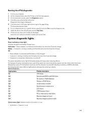
... 8. Diagnostics Light pattern Problem description 2,1 CPU failure 2,2 System board: BIOS and ROM failure 2,3 No memory or RAM detected 2,4 Memory or RAM failure 2,5 Invalid memory installed 2,6 System board or chipset error 2,7 LCD failure 3,1 CMOS battery failure 3,2 PCI or video card or chip failure 3,3 Recovery image not found 3,4 Recovery image found but invalid Camera status light: Indicates whether the camera is detected. Computer is running on battery and the battery has more than 5 percent charge. • Computer is in sleep state...
... 8. Diagnostics Light pattern Problem description 2,1 CPU failure 2,2 System board: BIOS and ROM failure 2,3 No memory or RAM detected 2,4 Memory or RAM failure 2,5 Invalid memory installed 2,6 System board or chipset error 2,7 LCD failure 3,1 CMOS battery failure 3,2 PCI or video card or chip failure 3,3 Recovery image not found 3,4 Recovery image found but invalid Camera status light: Indicates whether the camera is detected. Computer is running on battery and the battery has more than 5 percent charge. • Computer is in sleep state...
Service Manual
Page 104
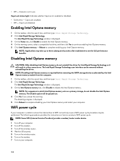
... WiFi connectivity issues a WiFi power cycle procedure may take up to three subsequent launches after enablement to conduct a WiFi power cycle: NOTE: Some ISPs (Internet Service Providers) provide a modem/router combo device. 1 Turn off the wireless router. 4 Wait for Intel Rapid Storage Technology as a primary storage, do not disable the Intel Optane memory. The disabling progress is not in a blue screen error. • Off - Camera is displayed. 5 Click Reboot to disable...
... WiFi connectivity issues a WiFi power cycle procedure may take up to three subsequent launches after enablement to conduct a WiFi power cycle: NOTE: Some ISPs (Internet Service Providers) provide a modem/router combo device. 1 Turn off the wireless router. 4 Wait for Intel Rapid Storage Technology as a primary storage, do not disable the Intel Optane memory. The disabling progress is not in a blue screen error. • Off - Camera is displayed. 5 Click Reboot to disable...
Setup and Specifications
Page 6
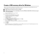
... Windows using the USB recovery drive, see the Troubleshooting section of Windows installed. Refer to the Microsoft support site for Windows Create a recovery drive to troubleshoot and fix problems that all data in the USB flash drive will be deleted. 7 Click Create. 8 Click Finish. The Recovery Drive window is displayed. 4 Click Yes to continue. The User Account Control window is displayed. 5 Select Back up to an hour to complete. Create a USB recovery drive for latest instructions. 1 Connect the USB flash drive to your product's Service Manual at www.dell.com/support/manuals...
... Windows using the USB recovery drive, see the Troubleshooting section of Windows installed. Refer to the Microsoft support site for Windows Create a recovery drive to troubleshoot and fix problems that all data in the USB flash drive will be deleted. 7 Click Create. 8 Click Finish. The Recovery Drive window is displayed. 4 Click Yes to continue. The User Account Control window is displayed. 5 Select Back up to an hour to complete. Create a USB recovery drive for latest instructions. 1 Connect the USB flash drive to your product's Service Manual at www.dell.com/support/manuals...
Setup and Specifications
Page 20
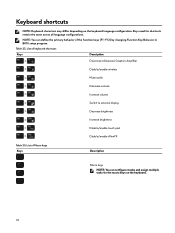
... changing Function Key Behavior in BIOS setup program. Table 22. NOTE: You can configure modes and assign multiple tasks for shortcuts remain the same across all language configurations. List of Macro keys Keys Description Macro keys NOTE: You can define the primary behavior of keyboard shortcuts Keys Description Disconnect Alienware Graphics Amplifier Disable/enable wireless Mute audio Decrease volume Increase volume Switch to external display Decrease brightness Increase brightness Disable/enable touch pad Disable/enable AlienFX Table 23. Keys used for the macro keys on...
... changing Function Key Behavior in BIOS setup program. Table 22. NOTE: You can configure modes and assign multiple tasks for shortcuts remain the same across all language configurations. List of Macro keys Keys Description Macro keys NOTE: You can define the primary behavior of keyboard shortcuts Keys Description Disconnect Alienware Graphics Amplifier Disable/enable wireless Mute audio Decrease volume Increase volume Switch to external display Decrease brightness Increase brightness Disable/enable touch pad Disable/enable AlienFX Table 23. Keys used for the macro keys on...
Setup and Specifications
Page 21
... game-specific lighting maps to customize and enhance the gaming experience. You can quickly access settings such as profiles, macros, AlienFX, and game library. AWCC supports the following features: • FX: Create and manage the AlienFX zones. • Fusion: Includes the ability to adjust game-specific Power Management, Sound Management, and Thermal Management features. • Peripheral Management: Enables peripherals to the gaming experience. The AWCC dashboard displays most...
... game-specific lighting maps to customize and enhance the gaming experience. You can quickly access settings such as profiles, macros, AlienFX, and game library. AWCC supports the following features: • FX: Create and manage the AlienFX zones. • Fusion: Includes the ability to adjust game-specific Power Management, Sound Management, and Thermal Management features. • Peripheral Management: Enables peripherals to the gaming experience. The AWCC dashboard displays most...


