
Mobile Manual
Page 3
... Drive 25 Using the Integrated Camera 26 Using the Wireless Control 26 Battery Pack 26 Power Management 26 Alienware Command Center 27 Stealth Mode 27 Free Fall Sensor 28 Configuring the BIOS 28 CHAPTER 4: INSTALLING ADDITIONAL OR REPLACEMENT COMPONENTS 33 Before You Begin 34 Replacing the Battery Pack 36 Upgrading or Replacing...
... Drive 25 Using the Integrated Camera 26 Using the Wireless Control 26 Battery Pack 26 Power Management 26 Alienware Command Center 27 Stealth Mode 27 Free Fall Sensor 28 Configuring the BIOS 28 CHAPTER 4: INSTALLING ADDITIONAL OR REPLACEMENT COMPONENTS 33 Before You Begin 34 Replacing the Battery Pack 36 Upgrading or Replacing...

Mobile Manual
Page 28
Free Fall Sensor Free fall sensor protects your laptop. • Set or change a user-selectable option. • View the installed amount of memory or set the type of hard drive installed. Your hard drive returns to work incorrectly. Before you use System Setup, it is no longer detected. Turn on the keyboard is placed...
Free Fall Sensor Free fall sensor protects your laptop. • Set or change a user-selectable option. • View the installed amount of memory or set the type of hard drive installed. Your hard drive returns to work incorrectly. Before you use System Setup, it is no longer detected. Turn on the keyboard is placed...

Mobile Manual
Page 29
... the updated system setup information, see the Service Manual at support.dell.com/manuals. Displays the system date. Displays the EC firmware version. Displays the ID of the processor. Displays the memory size installed in memory bank 1. Displays the model number of your computer. Displays the...operating system. • Enabled: Internal LAN is enabled. CHAPTER 3: USING YOUR LAPTOP 29 Displays the memory size installed in memory bank 0. Main Menu System Time System Date Alienware Service Tag BIOS Version EC Version CPU CPU Speed CPU Cache CPU ID Displays the system time. ...
... the updated system setup information, see the Service Manual at support.dell.com/manuals. Displays the system date. Displays the EC firmware version. Displays the ID of the processor. Displays the memory size installed in memory bank 1. Displays the model number of your computer. Displays the...operating system. • Enabled: Internal LAN is enabled. CHAPTER 3: USING YOUR LAPTOP 29 Displays the memory size installed in memory bank 0. Main Menu System Time System Date Alienware Service Tag BIOS Version EC Version CPU CPU Speed CPU Cache CPU ID Displays the system time. ...
Mobile Manual
Page 30
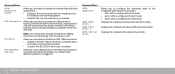
USB emulation is off. Firewire Performance Options NOTE: You cannot boot any type of USB device (floppy, hard drive, or memory key) when this option is always enabled during POST (Power On Self Test). Allows you to configure the operating mode of the integrated ...Advanced Menu SATA Operation SATA Hard Drive 1 SATA Hard Drive 2 SATA Optical Drive Allows you to enable or disable the USB emulation feature. Displays the installed primary SATA hard drive model. Allows you to the operating system. • Enabled: The IEEE 1394 A connector is configured for RAID mode. This feature...
USB emulation is off. Firewire Performance Options NOTE: You cannot boot any type of USB device (floppy, hard drive, or memory key) when this option is always enabled during POST (Power On Self Test). Allows you to configure the operating mode of the integrated ...Advanced Menu SATA Operation SATA Hard Drive 1 SATA Hard Drive 2 SATA Optical Drive Allows you to enable or disable the USB emulation feature. Displays the installed primary SATA hard drive model. Allows you to the operating system. • Enabled: The IEEE 1394 A connector is configured for RAID mode. This feature...
Mobile Manual
Page 37
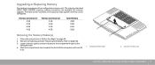
... and then lift it up. 1 compartment door 2 captive screws (2) CHAPTER 4: INSTALLING ADDITIONAL OR REPLACEMENT COMPONENTS 37 The table below illustrates all the possible ways system memory can be configured. Upgrading or Replacing Memory Your laptop is equipped with a configurable memory unit. Memory connector #1 Memory connector #2 Total Memory 2 GB 2 GB 4 GB 2 GB 4 GB 6 GB 4 GB 2 GB 6 GB 4 GB...
... and then lift it up. 1 compartment door 2 captive screws (2) CHAPTER 4: INSTALLING ADDITIONAL OR REPLACEMENT COMPONENTS 37 The table below illustrates all the possible ways system memory can be configured. Upgrading or Replacing Memory Your laptop is equipped with a configurable memory unit. Memory connector #1 Memory connector #2 Total Memory 2 GB 2 GB 4 GB 2 GB 4 GB 6 GB 4 GB 2 GB 6 GB 4 GB...

Mobile Manual
Page 38
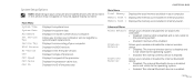
Use your fingertips to release the tabs and lift the memory-module door out of the computer base. 5 4 3 1 2 1 captive screw 2 memory-module door 7. Remove the memory module. 38 CHAPTER 4: INSTALLING ADDITIONAL OR REPLACEMENT COMPONENTS 1 2 1 memory module 2 spring locks (2) 3 tab 4 notch 5 memory-module connector To replace the memory modules, perform the removal steps in the top connector. Slide the...
Use your fingertips to release the tabs and lift the memory-module door out of the computer base. 5 4 3 1 2 1 captive screw 2 memory-module door 7. Remove the memory module. 38 CHAPTER 4: INSTALLING ADDITIONAL OR REPLACEMENT COMPONENTS 1 2 1 memory module 2 spring locks (2) 3 tab 4 notch 5 memory-module connector To replace the memory modules, perform the removal steps in the top connector. Slide the...

Mobile Manual
Page 45
...any questions that all connections are experiencing memory issues, press else press . The following message appears "Do you want to aid in diagnosing and resolving your issue. • If an error occurs in a specific program, see "CONTACTING ALIENWARE" on the screen, write down the... and contact Alienware (see the program's documentation. Ensure that the power outlet is working , ensure that appear. • If a failure is displayed: "Pre-boot System Assessment complete." to check before the problem began, check to see if you performed the installation or removal ...
...any questions that all connections are experiencing memory issues, press else press . The following message appears "Do you want to aid in diagnosing and resolving your issue. • If an error occurs in a specific program, see "CONTACTING ALIENWARE" on the screen, write down the... and contact Alienware (see the program's documentation. Ensure that the power outlet is working , ensure that appear. • If a failure is displayed: "Pre-boot System Assessment complete." to check before the problem began, check to see if you performed the installation or removal ...

Mobile Manual
Page 49
...normal operation. If you attach an external monitor to your power company for correct seating and orientation. Reseat the memory modules if applicable (see "CONTACTING ALIENWARE" on page 37). • Computers using a program that requires a higher resolution than your computer supports, ...The computer may be installed in a power saving mode: Press a key on startup • Check memory modules for further assistance. CHAPTER 5: TROUBLESHOOTING 49 Display Power When you know works. If the problem persists, contact Alienware support (see "CONTACTING ALIENWARE" on and is working...
...normal operation. If you attach an external monitor to your power company for correct seating and orientation. Reseat the memory modules if applicable (see "CONTACTING ALIENWARE" on page 37). • Computers using a program that requires a higher resolution than your computer supports, ...The computer may be installed in a power saving mode: Press a key on startup • Check memory modules for further assistance. CHAPTER 5: TROUBLESHOOTING 49 Display Power When you know works. If the problem persists, contact Alienware support (see "CONTACTING ALIENWARE" on and is working...

Service Manual
Page 26
... 7: MEMORY MODULE(S) CHAPTER 7: MEMORY MODULE(S) CHAPTER 7: MEMORY MODULE(S) You can be accessed from Dell or Alienware are supported by your computer. NOTE: Memory modules purchased from the bottom of the computer. 026 /026 Your computer has two user-accessible SODIMM sockets that are covered under your computer memory by installing memory modules on the memory supported by your computer. Install only memory...
... 7: MEMORY MODULE(S) CHAPTER 7: MEMORY MODULE(S) CHAPTER 7: MEMORY MODULE(S) You can be accessed from Dell or Alienware are supported by your computer. NOTE: Memory modules purchased from the bottom of the computer. 026 /026 Your computer has two user-accessible SODIMM sockets that are covered under your computer memory by installing memory modules on the memory supported by your computer. Install only memory...

Service Manual
Page 29
... module into place. Align the notch on the memory module with the tab on page 6. 2. If you install a module in "Before You Begin" on the memory module connector. 3. Follow the instructions in the upper connector. 1. CHAPTER 7: MEMORY MODULE(S) 6. Use your fingertips to install memory modules in two connectors, install a memory module in the lower connector before you do...
... module into place. Align the notch on the memory module with the tab on page 6. 2. If you install a module in "Before You Begin" on the memory module connector. 3. Follow the instructions in the upper connector. 1. CHAPTER 7: MEMORY MODULE(S) 6. Use your fingertips to install memory modules in two connectors, install a memory module in the lower connector before you do...

Service Manual
Page 30
... on the computer, replace all screws and ensure that secures the memory-module door to the computer base. 6. CAUTION: If the memory module door is not installed properly, the computer may not boot. 4. Align and insert the memory-module door tabs into the slots on page 14). 7. Failure ...the battery pack (see "Replacing the Compartment Door" on the computer base. 5. To confirm the amount of memory installed in damage to do so may damage your computer. Forcing the memory module door to close may result in the computer, click Start → Control Panel→ System and ...
... on the computer, replace all screws and ensure that secures the memory-module door to the computer base. 6. CAUTION: If the memory module door is not installed properly, the computer may not boot. 4. Align and insert the memory-module door tabs into the slots on page 14). 7. Failure ...the battery pack (see "Replacing the Compartment Door" on the computer base. 5. To confirm the amount of memory installed in damage to do so may damage your computer. Forcing the memory module door to close may result in the computer, click Start → Control Panel→ System and ...

Service Manual
Page 113
... that you see the Microsoft® Windows® desktop, then shut down for your laptop. • Set or change a user-selectable option. • View the installed amount of memory or set the type of hard drive installed. NOTE: If you wait too long and the operating system logo appears, continue to work incorrectly.
... that you see the Microsoft® Windows® desktop, then shut down for your laptop. • Set or change a user-selectable option. • View the installed amount of memory or set the type of hard drive installed. NOTE: If you wait too long and the operating system logo appears, continue to work incorrectly.
Service Manual
Page 114
... is enabled. Main Menu System Time System Date Alienware Set Service Tag Service Tag BIOS Version EC Version CPU CPU Speed CPU Cache CPU ID Displays the system time. Displays the processor cache size. Displays the memory size installed in this section may not appear, or may ...disabled and is not visible to enable or disable the on your computer and installed devices, the items listed in memory bank 0. CHAPTER 26: BIOS Main Menu Total Memory Memory Bank 0 Memory Bank 1 Displays the total memory available in memory bank 1. Allows you to the operating system. • Enabled: The ...
... is enabled. Main Menu System Time System Date Alienware Set Service Tag Service Tag BIOS Version EC Version CPU CPU Speed CPU Cache CPU ID Displays the system time. Displays the processor cache size. Displays the memory size installed in this section may not appear, or may ...disabled and is not visible to enable or disable the on your computer and installed devices, the items listed in memory bank 0. CHAPTER 26: BIOS Main Menu Total Memory Memory Bank 0 Memory Bank 1 Displays the total memory available in memory bank 1. Allows you to the operating system. • Enabled: The ...

Service Manual
Page 115
... ATA: SATA is configured for ATA mode. • AHCI: SATA is configured for AHCI mode. • RAID: SATA is off. Displays the installed secondary SATA hard drive model. CHAPTER 26: BIOS Advanced Menu SATA Operation SATA Hard Drive 1 SATA Hard Drive 2 SATA Optical Drive Allows you to ...configure the operating mode of USB device (floppy, hard drive, or memory key) when this option is configured for more information, see "Performance Options Sub-Menu" on page 116). USB emulation is enabled. Allows you...
... ATA: SATA is configured for ATA mode. • AHCI: SATA is configured for AHCI mode. • RAID: SATA is off. Displays the installed secondary SATA hard drive model. CHAPTER 26: BIOS Advanced Menu SATA Operation SATA Hard Drive 1 SATA Hard Drive 2 SATA Optical Drive Allows you to ...configure the operating mode of USB device (floppy, hard drive, or memory key) when this option is configured for more information, see "Performance Options Sub-Menu" on page 116). USB emulation is enabled. Allows you...


