Owner's Manual
Page 5
... Power-Button Board 45 Prerequisites 45 Procedure 45 Replacing the Power-Button Board 46 Procedure 46 Postrequisites 46 Removing the Status-Light Board 47 Prerequisites 47 Procedure 48 Replacing the Status-Light Board 49 Procedure 49 Postrequisites 49 Removing the Keyboard 50 Prerequisites 50 Procedure 51 Replacing the Keyboard 53 Procedure 53...
... Power-Button Board 45 Prerequisites 45 Procedure 45 Replacing the Power-Button Board 46 Procedure 46 Postrequisites 46 Removing the Status-Light Board 47 Prerequisites 47 Procedure 48 Replacing the Status-Light Board 49 Procedure 49 Postrequisites 49 Removing the Keyboard 50 Prerequisites 50 Procedure 51 Replacing the Keyboard 53 Procedure 53...

Owner's Manual
Page 7
... Removing the Logo Board 73 Prerequisites 73 Procedure 74 Replacing the Logo Board 75 Procedure 75 Postrequisites 75 Removing the Display-Light Boards 76 Prerequisites 76 Procedure 77 Replacing the Display-Light Boards 78 Procedure 78 Postrequisites 78 Removing the Speakers 79 Prerequisites 79 Procedure 80 Replacing the Speakers 81 Procedure 81...
... Removing the Logo Board 73 Prerequisites 73 Procedure 74 Replacing the Logo Board 75 Procedure 75 Postrequisites 75 Removing the Display-Light Boards 76 Prerequisites 76 Procedure 77 Replacing the Display-Light Boards 78 Procedure 78 Postrequisites 78 Removing the Speakers 79 Prerequisites 79 Procedure 80 Replacing the Speakers 81 Procedure 81...
Owner's Manual
Page 41
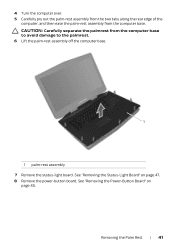
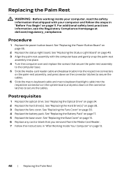
CAUTION: Carefully separate the palmrest from the computer base. See "Removing the Status-Light Board" on page 45. 4 Turn the computer over. 5 Carefully pry out the palm-rest assembly from the two tabs along the rear edge of the computer, and then ease the palm-rest assembly from the computer base to avoid damage to the palmrest. 6 Lift the palm-rest assembly off the computer base. 1 1 palm-rest assembly 7 Remove the status-light board. See "Removing the Power-Button Board" on page 47. 8 Remove the power-button board. Removing the Palm Rest | 41
CAUTION: Carefully separate the palmrest from the computer base. See "Removing the Status-Light Board" on page 45. 4 Turn the computer over. 5 Carefully pry out the palm-rest assembly from the two tabs along the rear edge of the computer, and then ease the palm-rest assembly from the computer base to avoid damage to the palmrest. 6 Lift the palm-rest assembly off the computer base. 1 1 palm-rest assembly 7 Remove the status-light board. See "Removing the Power-Button Board" on page 47. 8 Remove the power-button board. Removing the Palm Rest | 41
Owner's Manual
Page 42
... the Power-Button Board" on page 24. 2 Replace the hard drive(s). See "Replacing the Optical Drive" on page 46. 2 Replace the status-light board. See "Replacing the Status-Light Board" on page 49. 3 Align the palm-rest assembly with your computer, read the safety information that shipped with the computer base and... pack. See "Replacing the Fans Cover" on page 28. 3 Replace the fans cover. For additional safety best practices information, see the Regulatory Compliance Homepage at dell.com/regulatory_compliance.
... the Power-Button Board" on page 24. 2 Replace the hard drive(s). See "Replacing the Optical Drive" on page 46. 2 Replace the status-light board. See "Replacing the Status-Light Board" on page 49. 3 Align the palm-rest assembly with your computer, read the safety information that shipped with the computer base and... pack. See "Replacing the Fans Cover" on page 28. 3 Replace the fans cover. For additional safety best practices information, see the Regulatory Compliance Homepage at dell.com/regulatory_compliance.
Owner's Manual
Page 45
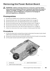
...inside your computer and follow the steps in Removing the Palm Rest. For additional safety best practices information, see the Regulatory Compliance Homepage at dell.com/regulatory_compliance. See "Removing the Fans Cover" on page 25. 6 Remove the optical drive. Prerequisites 1 Remove any installed card or blank...on page 11. Procedure 1 Lift the connector latch and pull the pull-tab to step 6 in "Before You Begin" on the status-light board. 2 Remove the screws that shipped with your computer, read the safety information that secure the power-button board to the palm-rest ...
...inside your computer and follow the steps in Removing the Palm Rest. For additional safety best practices information, see the Regulatory Compliance Homepage at dell.com/regulatory_compliance. See "Removing the Fans Cover" on page 25. 6 Remove the optical drive. Prerequisites 1 Remove any installed card or blank...on page 11. Procedure 1 Lift the connector latch and pull the pull-tab to step 6 in "Before You Begin" on the status-light board. 2 Remove the screws that shipped with your computer, read the safety information that secure the power-button board to the palm-rest ...
Owner's Manual
Page 46
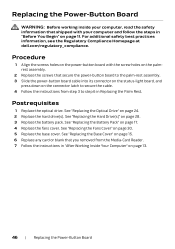
For additional safety best practices information, see the Regulatory Compliance Homepage at dell.com/regulatory_compliance. Procedure 1 Align the screws holes on the power-button board with your computer, read the safety information that shipped with the screw holes ... the screws that secure the power-button board to the palm-rest assembly. 3 Slide the power-button board cable into its connector on the status-light board, and press down on the connector latch to secure the cable. 4 Follow the instructions from the Media-Card Reader. 7 Follow the instructions in "After...
For additional safety best practices information, see the Regulatory Compliance Homepage at dell.com/regulatory_compliance. Procedure 1 Align the screws holes on the power-button board with your computer, read the safety information that shipped with the screw holes ... the screws that secure the power-button board to the palm-rest assembly. 3 Slide the power-button board cable into its connector on the status-light board, and press down on the connector latch to secure the cable. 4 Follow the instructions from the Media-Card Reader. 7 Follow the instructions in "After...
Owner's Manual
Page 47
... Drive" on page 11. For additional safety best practices information, see the Regulatory Compliance Homepage at dell.com/regulatory_compliance. See "Removing the Base Cover" on page 25. 6 Remove the optical drive. Removing the Status-Light Board WARNING: Before working inside your computer, read the safety information that shipped with your computer and...
... Drive" on page 11. For additional safety best practices information, see the Regulatory Compliance Homepage at dell.com/regulatory_compliance. See "Removing the Base Cover" on page 25. 6 Remove the optical drive. Removing the Status-Light Board WARNING: Before working inside your computer, read the safety information that shipped with your computer and...
Owner's Manual
Page 48
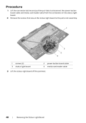
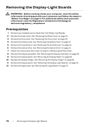
Procedure 1 Lift the connector latches and pull the pull-tabs to disconnect the power-button board cable and media-card reader cable from the connectors on the status-light board. 2 Remove the screws that secure the status-light board to the palm-rest assembly. 1 2 3 4 1 screws (2) 3 status-light board 2 power-button board cable 4 media-card reader cable 3 Lift the status-light board off the palmrest. 48 | Removing the Status-Light Board
Procedure 1 Lift the connector latches and pull the pull-tabs to disconnect the power-button board cable and media-card reader cable from the connectors on the status-light board. 2 Remove the screws that secure the status-light board to the palm-rest assembly. 1 2 3 4 1 screws (2) 3 status-light board 2 power-button board cable 4 media-card reader cable 3 Lift the status-light board off the palmrest. 48 | Removing the Status-Light Board
Owner's Manual
Page 49
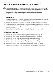
...on page 24. 2 Replace the hard drive(s). Replacing the Status-Light Board WARNING: Before working inside your computer and follow the steps ...fans cover. Replacing the Status-Light Board | 49 Procedure 1 Align the slots on the status-light board with your computer, read ... on the palm-rest assembly and secure the status-light board in place. 2 Replace the screws that you... Replace any card or blank that secure the status-light board to the palm-rest assembly. 3 Slide the power-...reader cable into the respective connectors on the status-light board, and press down on the connector latches to...
...on page 24. 2 Replace the hard drive(s). Replacing the Status-Light Board WARNING: Before working inside your computer and follow the steps ...fans cover. Replacing the Status-Light Board | 49 Procedure 1 Align the slots on the status-light board with your computer, read ... on the palm-rest assembly and secure the status-light board in place. 2 Replace the screws that you... Replace any card or blank that secure the status-light board to the palm-rest assembly. 3 Slide the power-...reader cable into the respective connectors on the status-light board, and press down on the connector latches to...

Owner's Manual
Page 74
Procedure 1 Remove the screws that secure the logo board to the display back-cover. 2 Carefully rotate the logo board over and disconnect the display-light board cables from the connectors on the logo board. 3 Lift the logo board off the display back-cover. 2 3 1 1 screws (2) 2 logo board 3 display-light board cables (4) 74 | Removing the Logo Board
Procedure 1 Remove the screws that secure the logo board to the display back-cover. 2 Carefully rotate the logo board over and disconnect the display-light board cables from the connectors on the logo board. 3 Lift the logo board off the display back-cover. 2 3 1 1 screws (2) 2 logo board 3 display-light board cables (4) 74 | Removing the Logo Board

Owner's Manual
Page 75
...Replacing the Display Bezel" on page 28. 8 Replace the battery pack. For additional safety best practices information, see the Regulatory Compliance Homepage at dell.com/regulatory_compliance. See "Replacing the Display Panel" on page 17. 9 Replace the fans cover. See "Replacing the Battery Pack" on page 72.... 2 Replace the display hinges. Replacing the Logo Board | 75 Procedure 1 Connect the display-light board cables to step 6 in "After Working Inside Your Computer" on page 13. See "Replacing the Optical Drive" on page 11. See "...
...Replacing the Display Bezel" on page 28. 8 Replace the battery pack. For additional safety best practices information, see the Regulatory Compliance Homepage at dell.com/regulatory_compliance. See "Replacing the Display Panel" on page 17. 9 Replace the fans cover. See "Replacing the Battery Pack" on page 72.... 2 Replace the display hinges. Replacing the Logo Board | 75 Procedure 1 Connect the display-light board cables to step 6 in "After Working Inside Your Computer" on page 13. See "Replacing the Optical Drive" on page 11. See "...
Owner's Manual
Page 76
...instructions from the Media-Card Reader. 2 Remove the base cover. See "Removing the Hard Drive(s)" on page 73. 76 | Removing the Display-Light Boards See "Removing the Logo Board" on page 25. 6 Remove the optical drive. See "Removing the Display Assembly" on page 64. 10...the display panel. For additional safety best practices information, see the Regulatory Compliance Homepage at dell.com/regulatory_compliance. See "Removing the Fans Cover" on page 11. Removing the Display-Light Boards WARNING: Before working inside your computer, read the safety information that shipped with your...
...instructions from the Media-Card Reader. 2 Remove the base cover. See "Removing the Hard Drive(s)" on page 73. 76 | Removing the Display-Light Boards See "Removing the Logo Board" on page 25. 6 Remove the optical drive. See "Removing the Display Assembly" on page 64. 10...the display panel. For additional safety best practices information, see the Regulatory Compliance Homepage at dell.com/regulatory_compliance. See "Removing the Fans Cover" on page 11. Removing the Display-Light Boards WARNING: Before working inside your computer, read the safety information that shipped with your...

Owner's Manual
Page 77
Procedure 1 Remove the screws that secure the display-light boards to the display back-cover. 2 Lift the display-light boards off the display back-cover. 1 2 1 screws (5) 2 display-light boards (3) Removing the Display-Light Boards | 77
Procedure 1 Remove the screws that secure the display-light boards to the display back-cover. 2 Lift the display-light boards off the display back-cover. 1 2 1 screws (5) 2 display-light boards (3) Removing the Display-Light Boards | 77

Owner's Manual
Page 78
.... 3 Replace the display hinges. See "Replacing the Display Assembly" on page 13. 78 | Replacing the Display-Light Boards Postrequisites 1 Replace the logo board. For additional safety best practices information, see the Regulatory Compliance Homepage at dell.com/regulatory_compliance. See "Replacing the Display Panel" on page 65. 5 Replace the display assembly. See "Replacing...
.... 3 Replace the display hinges. See "Replacing the Display Assembly" on page 13. 78 | Replacing the Display-Light Boards Postrequisites 1 Replace the logo board. For additional safety best practices information, see the Regulatory Compliance Homepage at dell.com/regulatory_compliance. See "Replacing the Display Panel" on page 65. 5 Replace the display assembly. See "Replacing...

Owner's Manual
Page 101
Procedure 1 Disconnect the speaker cable and the subwoofer cable from the connectors on the system board. 2 Lift the connector latch and disconnect the tron-light cables from the connectors on the system board. 2 1 3 5 1 tron-lights cable 1 3 tron-lights cable 3 5 speakers cable 4 2 tron-lights cable 2 4 subwoofer cable Removing the System Board | 101
Procedure 1 Disconnect the speaker cable and the subwoofer cable from the connectors on the system board. 2 Lift the connector latch and disconnect the tron-light cables from the connectors on the system board. 2 1 3 5 1 tron-lights cable 1 3 tron-lights cable 3 5 speakers cable 4 2 tron-lights cable 2 4 subwoofer cable Removing the System Board | 101
Owner's Manual
Page 103
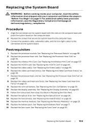
... on the computer base. 2 Replace the screws that secure the system board to the computer base. 3 Connect the speakers cable, subwoofer cable, and the tron-light cables to step 6 in "Before You Begin" on page 11. See "Replacing the Fans Cover" on page 28. 14 Replace the memory modules. See "...Card Heat-Sink(s)" on page 35. 8 Replace the video-card heat-sink fan(s). For additional safety best practices information, see the Regulatory Compliance Homepage at dell.com/regulatory_compliance. See "Replacing the Processor Heat-Sink Fan" on page 90. 7 Replace the processor heat-sink fan.
... on the computer base. 2 Replace the screws that secure the system board to the computer base. 3 Connect the speakers cable, subwoofer cable, and the tron-light cables to step 6 in "Before You Begin" on page 11. See "Replacing the Fans Cover" on page 28. 14 Replace the memory modules. See "...Card Heat-Sink(s)" on page 35. 8 Replace the video-card heat-sink fan(s). For additional safety best practices information, see the Regulatory Compliance Homepage at dell.com/regulatory_compliance. See "Replacing the Processor Heat-Sink Fan" on page 90. 7 Replace the processor heat-sink fan.
Quick Start Guide
Page 1
..., FAQs, and solutions to most common issues, see dell.com/Alienware For sales, technical support, or customer service issues, see dell.com/ContactDell © 2013 Dell Inc. Alienware™、AlienFX AlienHead Alienware Corporation Dell™ は、Dell Inc 2013 - 04 P19E P19E001 Alienware 18 R1 18 Quick Start Guide Camera-status light 3 3 4. USB 3.0 端口(2 个) 21. Left...
..., FAQs, and solutions to most common issues, see dell.com/Alienware For sales, technical support, or customer service issues, see dell.com/ContactDell © 2013 Dell Inc. Alienware™、AlienFX AlienHead Alienware Corporation Dell™ は、Dell Inc 2013 - 04 P19E P19E001 Alienware 18 R1 18 Quick Start Guide Camera-status light 3 3 4. USB 3.0 端口(2 个) 21. Left...


