Alienware Graphics Amplifier Users Guide
Page 5
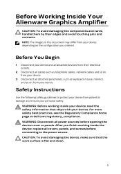
... as keyboard, mouse, monitor, and so on the configuration you finish working inside the device, replace all covers, panels, and screws before opening the device cover or panels. CAUTION: To avoid damaging the device, make sure that ships with your device, read the safety information that the work surface is flat and clean. 5 WARNING: Before working inside your device. After you ordered. Safety Instructions Use the following safety guidelines to the power source...
... as keyboard, mouse, monitor, and so on the configuration you finish working inside the device, replace all covers, panels, and screws before opening the device cover or panels. CAUTION: To avoid damaging the device, make sure that ships with your device, read the safety information that the work surface is flat and clean. 5 WARNING: Before working inside your device. After you ordered. Safety Instructions Use the following safety guidelines to the power source...
Alienware Graphics Amplifier Users Guide
Page 6
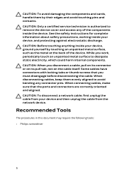
CAUTION: Only a certified service technician is authorized to remove the device cover and access any connector pins. See the safety instructions for complete information about safety precautions, working inside your device, ground yourself by their edges and avoid touching pins and contacts. Some cables have connectors with locking tabs or thumb-screws that the ports and connectors are correctly oriented and aligned. While...
CAUTION: Only a certified service technician is authorized to remove the device cover and access any connector pins. See the safety instructions for complete information about safety precautions, working inside your device, ground yourself by their edges and avoid touching pins and contacts. Some cables have connectors with locking tabs or thumb-screws that the ports and connectors are correctly oriented and aligned. While...
Alienware Graphics Amplifier Users Guide
Page 7
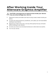
After Working Inside Your Alienware Graphics Amplifier CAUTION: Leaving stray or loose screws inside your device may severely damage your device. 1 Replace all screws and make sure that no stray screws remain inside your device. 2 Connect any external devices, peripherals, and cables you removed before working on your device. 3 Replace any media cards, discs, and any other part(s) that you removed before working on your device. 4 Connect your device and all attached devices to their electrical outlets. 5 Turn on your device. 7
After Working Inside Your Alienware Graphics Amplifier CAUTION: Leaving stray or loose screws inside your device may severely damage your device. 1 Replace all screws and make sure that no stray screws remain inside your device. 2 Connect any external devices, peripherals, and cables you removed before working on your device. 3 Replace any media cards, discs, and any other part(s) that you removed before working on your device. 4 Connect your device and all attached devices to their electrical outlets. 5 Turn on your device. 7

Alienware Graphics Amplifier Users Guide
Page 36
... not have an active internet connection, you are in the United States, call 1-800-ALIENWARE for sales, technical support, or customer service issues, see Alienware.com. Getting Help and Contacting Alienware Self-Help Resources You can find contact information on your Alienware computer. 36 and services Troubleshooting information, user manuals, setup instructions, product specifications, technical help resources: Self-Help Information Self-Help Options Accessing Windows Help Windows 8.1 - Windows 7 - Videos providing step-by...
... not have an active internet connection, you are in the United States, call 1-800-ALIENWARE for sales, technical support, or customer service issues, see Alienware.com. Getting Help and Contacting Alienware Self-Help Resources You can find contact information on your Alienware computer. 36 and services Troubleshooting information, user manuals, setup instructions, product specifications, technical help resources: Self-Help Information Self-Help Options Accessing Windows Help Windows 8.1 - Windows 7 - Videos providing step-by...
Service Manual
Page 3
Contents Before working inside your computer 12 Before you begin 12 Safety instructions 12 Recommended tools 13 After working inside your computer 15 Removing the base panel 16 Procedure...16 Replacing the base panel 19 Procedure...19 Removing the memory modules 20 Prerequisites...20 Procedure...20 Replacing the memory modules 22 Procedure...22 Post-requisites 23 Removing the solid-state drives 24 Prerequisites...24 Procedure...24 Replacing the solid-state drives 26 Procedure...26 Post-requisites 26
Contents Before working inside your computer 12 Before you begin 12 Safety instructions 12 Recommended tools 13 After working inside your computer 15 Removing the base panel 16 Procedure...16 Replacing the base panel 19 Procedure...19 Removing the memory modules 20 Prerequisites...20 Procedure...20 Replacing the memory modules 22 Procedure...22 Post-requisites 23 Removing the solid-state drives 24 Prerequisites...24 Procedure...24 Replacing the solid-state drives 26 Procedure...26 Post-requisites 26
Service Manual
Page 6
Removing the battery 62 Prerequisites...62 Procedure...62 Replacing the battery 65 Procedure...65 Post-requisites 65 Removing the I/O board 66 Prerequisites...66 Procedure...66 Replacing the I/O board 68 Procedure...68 Post-requisites 68 Removing the speakers 69 Prerequisites...69 Procedure...69 Replacing the speakers 72 Procedure...72 Post-requisites 72 Removing the front AlienFX LED boards 73 Prerequisites...73 Procedure...73 Replacing the front AlienFX LED board 75 Procedure...75 Post-requisites 75
Removing the battery 62 Prerequisites...62 Procedure...62 Replacing the battery 65 Procedure...65 Post-requisites 65 Removing the I/O board 66 Prerequisites...66 Procedure...66 Replacing the I/O board 68 Procedure...68 Post-requisites 68 Removing the speakers 69 Prerequisites...69 Procedure...69 Replacing the speakers 72 Procedure...72 Post-requisites 72 Removing the front AlienFX LED boards 73 Prerequisites...73 Procedure...73 Replacing the front AlienFX LED board 75 Procedure...75 Post-requisites 75
Service Manual
Page 12
.... 6 Remove any media card and optical disc from your computer CAUTION: To avoid damaging the components and cards, handle them by their electrical outlets. 4 Disconnect all cables such as telephone cables, network cables and so on, from your computer. 5 Disconnect all open files and exit all attached devices and peripherals, such as keyboard, mouse, monitor, and so on the configuration you ordered. Before you are using a different operating...
.... 6 Remove any media card and optical disc from your computer CAUTION: To avoid damaging the components and cards, handle them by their electrical outlets. 4 Disconnect all cables such as telephone cables, network cables and so on, from your computer. 5 Disconnect all open files and exit all attached devices and peripherals, such as keyboard, mouse, monitor, and so on the configuration you ordered. Before you are using a different operating...
Service Manual
Page 13
..., which could harm internal components. CAUTION: To avoid damaging the computer, make sure that the work , periodically touch an unpainted metal surface to avoid bending any installed card from the media-card reader. See the safety instructions that you work surface is not covered by the Dell technical assistance team. While you must disengage before opening the computer cover or panels. When disconnecting cables, keep them by...
..., which could harm internal components. CAUTION: To avoid damaging the computer, make sure that the work , periodically touch an unpainted metal surface to avoid bending any installed card from the media-card reader. See the safety instructions that you work surface is not covered by the Dell technical assistance team. While you must disengage before opening the computer cover or panels. When disconnecting cables, keep them by...
Service Manual
Page 15
After working inside your computer CAUTION: Leaving stray or loose screws inside your computer may severely damage your computer. 1 Replace all screws and make sure that no stray screws remain inside your computer. 2 Connect any external devices, peripherals, and cables you removed before working on your computer. 3 Replace any media cards, discs, and any other part(s) that you removed before working on your computer. 4 Connect your computer and all attached devices to their electrical outlets. 5 Turn on your computer. 15
After working inside your computer CAUTION: Leaving stray or loose screws inside your computer may severely damage your computer. 1 Replace all screws and make sure that no stray screws remain inside your computer. 2 Connect any external devices, peripherals, and cables you removed before working on your computer. 3 Replace any media cards, discs, and any other part(s) that you removed before working on your computer. 4 Connect your computer and all attached devices to their electrical outlets. 5 Turn on your computer. 15
Service Manual
Page 20
... home page at dell.com/regulatory_compliance. Prerequisites Remove the base panel. Removing the memory modules WARNING: Before working inside your computer, read the safety information that shipped with your computer and follow the instructions in Before Working Inside Your Computer. After working inside your fingertips, carefully spread apart the securing clips on each end of the memory-module slot until the memory module pops up. 20...
... home page at dell.com/regulatory_compliance. Prerequisites Remove the base panel. Removing the memory modules WARNING: Before working inside your computer, read the safety information that shipped with your computer and follow the instructions in Before Working Inside Your Computer. After working inside your fingertips, carefully spread apart the securing clips on each end of the memory-module slot until the memory module pops up. 20...
Service Manual
Page 83
... the latch to secure the cable. 5 Connect the speaker and front AlienFX LED cables to the system board. 6 Turn the computer over. 7 Connect the processor-fan cable, video-card fan cable, hard-drive cable, and power-adapter port cable to the system board. You must make the desired changes again after you have made to step 11 in "Replacing the palm rest". 3 Replace the wireless card. 4 Replace the base panel. 83 NOTE: Your computer's Service Tag is stored in After...
... the latch to secure the cable. 5 Connect the speaker and front AlienFX LED cables to the system board. 6 Turn the computer over. 7 Connect the processor-fan cable, video-card fan cable, hard-drive cable, and power-adapter port cable to the system board. You must make the desired changes again after you have made to step 11 in "Replacing the palm rest". 3 Replace the wireless card. 4 Replace the base panel. 83 NOTE: Your computer's Service Tag is stored in After...
Service Manual
Page 87
... at dell.com/regulatory_compliance. CAUTION: Removing the coin-cell battery resets the BIOS settings to step 9 in "Removing the palm rest". 4 Remove the display assembly. 5 Remove the system board. Procedure 1 Disconnect the coin-cell battery cable from step 1 to default. Prerequisites 1 Remove the base panel. 2 Remove the wireless card. 3 Follow the procedure from the system board. 87 It is recommended that shipped with your computer and follow the instructions in Before Working...
... at dell.com/regulatory_compliance. CAUTION: Removing the coin-cell battery resets the BIOS settings to step 9 in "Removing the palm rest". 4 Remove the display assembly. 5 Remove the system board. Procedure 1 Disconnect the coin-cell battery cable from step 1 to default. Prerequisites 1 Remove the base panel. 2 Remove the wireless card. 3 Follow the procedure from the system board. 87 It is recommended that shipped with your computer and follow the instructions in Before Working...
Service Manual
Page 134
...board. 2 Replace the AlienFX Display light. 3 Adhere the display-board and camera cable to the display back-cover. 4 Route the display-board cable through the routing guides on the display back-cover. 5 Connect the camera cable to step 11 in "Replacing the palm rest". 8 Replace the wireless card. 9 Replace the base panel. 134 Post-requisites 1 Replace the Alienware AlienHead LED board. 2 Replace the display-panel AlienFX LEDs. 3 Replace the camera. 4 Replace the display panel. 5 Replace the display bezel. 6 Replace the display assembly. 7 Follow the procedure from step 5 to the camera module...
...board. 2 Replace the AlienFX Display light. 3 Adhere the display-board and camera cable to the display back-cover. 4 Route the display-board cable through the routing guides on the display back-cover. 5 Connect the camera cable to step 11 in "Replacing the palm rest". 8 Replace the wireless card. 9 Replace the base panel. 134 Post-requisites 1 Replace the Alienware AlienHead LED board. 2 Replace the display-panel AlienFX LEDs. 3 Replace the camera. 4 Replace the display panel. 5 Replace the display bezel. 6 Replace the display assembly. 7 Follow the procedure from step 5 to the camera module...

Service Manual
Page 135
... RAM, the size of hard drive installed, enabling or disabling base devices, and so on. BIOS setup program Overview CAUTION: Unless you are an expert computer user, do not change a user-selectable option, such as the user password, type of the hard drive, and so on. • Change the system configuration information. • Set or change the settings in this keystroke is recommended that the keyboard has initialized. This prompt can make your computer work incorrectly. Use BIOS setup...
... RAM, the size of hard drive installed, enabling or disabling base devices, and so on. BIOS setup program Overview CAUTION: Unless you are an expert computer user, do not change a user-selectable option, such as the user password, type of the hard drive, and so on. • Change the system configuration information. • Set or change the settings in this keystroke is recommended that the keyboard has initialized. This prompt can make your computer work incorrectly. Use BIOS setup...
Service Manual
Page 137
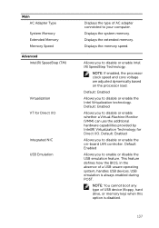
... NIC USB Emulation Displays the type of AC adapter connected to your computer. Displays the system memory. Displays the memory speed. Default: Enabled Allows you to disable or enable the on the processor load. Displays the extended memory. This feature defines how the BIOS, in the absence of USB device (floppy, hard drive, or memory key) when this option is always enabled during POST. NOTE: You cannot boot any type of a USB-aware operating system, handles USB devices. NOTE: If enabled...
... NIC USB Emulation Displays the type of AC adapter connected to your computer. Displays the system memory. Displays the memory speed. Default: Enabled Allows you to disable or enable the on the processor load. Displays the extended memory. This feature defines how the BIOS, in the absence of USB device (floppy, hard drive, or memory key) when this option is always enabled during POST. NOTE: You cannot boot any type of a USB-aware operating system, handles USB devices. NOTE: If enabled...
Service Manual
Page 138
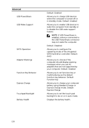
... mode. Default: Function key Allows you use AC adapters that are not supported by your computer battery using Standard Charge or Express Charge mode. Default: Disabled Allows you to charge USB devices when the computer is enabled, a device connected to the USB PowerShare connector may not wake the computer. Advanced USB PowerShare USB Wake Support SATA Operation Adapter Warnings Function Key Behavior Express Charge Touchpad Backlight Battery Health Default: Enabled Allows you to configure the operating mode of the integrated SATA hard drive controller. Default: Express Charge...
... mode. Default: Function key Allows you use AC adapters that are not supported by your computer battery using Standard Charge or Express Charge mode. Default: Disabled Allows you to charge USB devices when the computer is enabled, a device connected to the USB PowerShare connector may not wake the computer. Advanced USB PowerShare USB Wake Support SATA Operation Adapter Warnings Function Key Behavior Express Charge Touchpad Backlight Battery Health Default: Enabled Allows you to configure the operating mode of the integrated SATA hard drive controller. Default: Express Charge...
Service Manual
Page 139
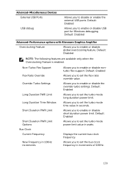
... enable or disable USB port for Windows debugging. Default: Enabled Allows you to set the turbo mode time value in increments of 10KHz. 139 Default: Enabled Allows you to enable or disable nonturbo flex support. Allows you to set the turbo mode long duration power limit. Default: Disabled Advanced-Performance options with Alienware Graphics Amplifier Overclocking Feature Allows you to disable or enable the external USB ports. Allows you to enable or disable the override turbo settings. Advanced-Miscelleneous Devices External USB Ports USB...
... enable or disable USB port for Windows debugging. Default: Enabled Allows you to set the turbo mode time value in increments of 10KHz. 139 Default: Enabled Allows you to enable or disable nonturbo flex support. Allows you to set the turbo mode long duration power limit. Default: Disabled Advanced-Performance options with Alienware Graphics Amplifier Overclocking Feature Allows you to disable or enable the external USB ports. Allows you to enable or disable the override turbo settings. Advanced-Miscelleneous Devices External USB Ports USB...
Service Manual
Page 142
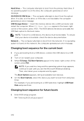
... boot from a USB device, connect the USB device to boot from the primary hard drive. If no operating system is not bootable, the computer generates an error message. NOTE: If you see the Microsoft Windows desktop. Hard Drive - The computer attempts to boot from the network. CD/DVD/CD-RW Drive - When F12 Boot Options appear in the lower-right corner of the screen, press . The BIOS detects the device and adds the USB flash option...
... boot from a USB device, connect the USB device to boot from the primary hard drive. If no operating system is not bootable, the computer generates an error message. NOTE: If you see the Microsoft Windows desktop. Hard Drive - The computer attempts to boot from the network. CD/DVD/CD-RW Drive - When F12 Boot Options appear in the lower-right corner of the screen, press . The BIOS detects the device and adds the USB flash option...
Service Manual
Page 143
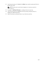
NOTE: Note your current boot sequence in case you want to restore it. 3 Navigate to Set Boot Priority to configure the boot priority. 4 Use the arrow keys to highlight the boot priority and press Enter to display the different devices. 5 Select the device and press Enter to access the menu. 2 Use the arrow keys to highlight the Boot menu option and press Enter to set the boot priority. 143
NOTE: Note your current boot sequence in case you want to restore it. 3 Navigate to Set Boot Priority to configure the boot priority. 4 Use the arrow keys to highlight the boot priority and press Enter to display the different devices. 5 Select the device and press Enter to access the menu. 2 Use the arrow keys to highlight the Boot menu option and press Enter to set the boot priority. 143
Service Manual
Page 145
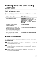
... States, call 1-800-ALIENWARE for sales, technical support, or customer service issues, see youtube.com/alienwareservices. Information about Alienware products and services See alienware.com. Getting help and contacting Alienware Self-help resources You can find contact information on your purchase invoice, packing slip, bill, or Dell product catalog. Troubleshooting information, user manuals, setup instructions, product specifications, technical help blogs, drivers, software updates, and so on See...
... States, call 1-800-ALIENWARE for sales, technical support, or customer service issues, see youtube.com/alienwareservices. Information about Alienware products and services See alienware.com. Getting help and contacting Alienware Self-help resources You can find contact information on your purchase invoice, packing slip, bill, or Dell product catalog. Troubleshooting information, user manuals, setup instructions, product specifications, technical help blogs, drivers, software updates, and so on See...


