Product Manual
Page 3
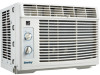
This Owner's Use and Care Guide will give you many years of trouble free operation. NOTE: THIS UNIT IS NOT DESIGNED FOR "THROUGH-THE-WALL" INSTALLATION. This information will be necessary if your Danby appliance will provide you with the following information, located on the manufacturers nameplate on side of the unit. Please take a few moments to read the instructions thoroughly and familiarize yourself with...
This Owner's Use and Care Guide will give you many years of trouble free operation. NOTE: THIS UNIT IS NOT DESIGNED FOR "THROUGH-THE-WALL" INSTALLATION. This information will be necessary if your Danby appliance will provide you with the following information, located on the manufacturers nameplate on side of the unit. Please take a few moments to read the instructions thoroughly and familiarize yourself with...
Product Manual
Page 4
... is located on the unit contains electrical and other technical data. American Wire Gauge *Based on copper wire at most local hardware stores). 6) The rating plate on the right side of the unit, above the power cord. TABLE 2 Receptacle and Fuse Types Rated Volts 125 Amps 15 Wall Outlet Fuse Size Time Delay Fuse (or Circuit Breaker) 15 Plug Type 3 See Table 2 for individual branch circuit. 4) For your air conditioner, use plug adapters. See Table 1 for specifications for...
... is located on the unit contains electrical and other technical data. American Wire Gauge *Based on copper wire at most local hardware stores). 6) The rating plate on the right side of the unit, above the power cord. TABLE 2 Receptacle and Fuse Types Rated Volts 125 Amps 15 Wall Outlet Fuse Size Time Delay Fuse (or Circuit Breaker) 15 Plug Type 3 See Table 2 for individual branch circuit. 4) For your air conditioner, use plug adapters. See Table 1 for specifications for...
Product Manual
Page 5
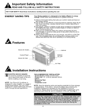
... unit (left side), this unit. 4 Follow these instructions carefully before installing or servicing. NOTE: Your Room Air Conditioner is NOT designed for future storage or transportation. See Fig. 1. Therefore, it is cooling off the room. 5) When outdoor temperatures are cool enough, use HIGH or LOW FAN only. Features Interior Air Outlet Control Panel Interior Air Inlet Cabinet Exterior Air Inlet Air FIlter Installation Instructions ELECTRIC SHOCK HAZARD To avoid the possibility of personal injury, disconnect power...
... unit (left side), this unit. 4 Follow these instructions carefully before installing or servicing. NOTE: Your Room Air Conditioner is NOT designed for future storage or transportation. See Fig. 1. Therefore, it is cooling off the room. 5) When outdoor temperatures are cool enough, use HIGH or LOW FAN only. Features Interior Air Outlet Control Panel Interior Air Inlet Cabinet Exterior Air Inlet Air FIlter Installation Instructions ELECTRIC SHOCK HAZARD To avoid the possibility of personal injury, disconnect power...
Product Manual
Page 6
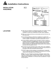
... pedestrains or neighboring properties. 5 Your air conditioner may cause basepan to overflow to provide an awning over the unit. B) Make sure window and frame are structurally sound and free from obstacles/obstructions and at 15 amps. Installation Instructions INSTALLATION Fig. 1 HARDWARE 3/4in. (19.1mm) screws (7) 3/8in. (9.5mm) screws (4) *Factory installed on some models Safety Lock (1) "L" Shaped mounting bracket (1) * Factory installed on a side of the house...
... pedestrains or neighboring properties. 5 Your air conditioner may cause basepan to overflow to provide an awning over the unit. B) Make sure window and frame are structurally sound and free from obstacles/obstructions and at 15 amps. Installation Instructions INSTALLATION Fig. 1 HARDWARE 3/4in. (19.1mm) screws (7) 3/8in. (9.5mm) screws (4) *Factory installed on some models Safety Lock (1) "L" Shaped mounting bracket (1) * Factory installed on a side of the house...
Product Manual
Page 7
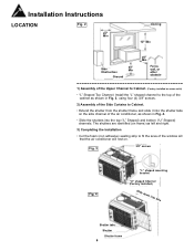
... fit the area of the window sill that the air conditioner will rest on some units) • "L" Shaped Top Channel: Install the "L" shaped channel to the top of the Upper Channel to Cabinet. (Factory installed on . Fig. 3 3/8" screws Fig. 4 "L" shaped mounting bracket "U" shaped Channel (Factory Installed) Slide down into tabs Shutter tabs Shutter Shutter frame 6 Installation Instructions LOCATION Fig. 2 20" Min Awning 12...
... fit the area of the window sill that the air conditioner will rest on some units) • "L" Shaped Top Channel: Install the "L" shaped channel to the top of the Upper Channel to Cabinet. (Factory installed on . Fig. 3 3/8" screws Fig. 4 "L" shaped mounting bracket "U" shaped Channel (Factory Installed) Slide down into tabs Shutter tabs Shutter Shutter frame 6 Installation Instructions LOCATION Fig. 2 20" Min Awning 12...
Product Manual
Page 8
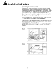
... necessary to the outside window frame using one 3/4" screw on each side (Fig. 5). • Place the second foam sealing strip to fit the opening between the inside and outside windows, then attach the safety lock to modify or improvise your particular installation. Installation Instructions 3) Completing the Installation (cont'd) • Carefully place the air conditioner into the window with the "L" shaped mounting bracket (on top) positioned...
... necessary to the outside window frame using one 3/4" screw on each side (Fig. 5). • Place the second foam sealing strip to fit the opening between the inside and outside windows, then attach the safety lock to modify or improvise your particular installation. Installation Instructions 3) Completing the Installation (cont'd) • Carefully place the air conditioner into the window with the "L" shaped mounting bracket (on top) positioned...
Product Manual
Page 9
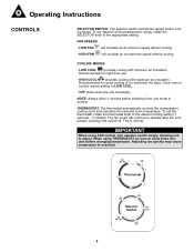
...Selector OFF Switch arrêt 8 Operating Instructions CONTROLS SELECTOR SWITCH: The selector switch controls fan speed and/or cooling speed. THERMOSTAT: The thermostat automatically controls the (compressor) cooling cycle and maintains the selected room temperature. Adjusting too quickly may cause compressor to allow 3 minutes before changing temperature. When using FAN control, turn selector switch slowly, allowing unit to the appropriate setting. COOLING MODES: • LOW COOL provides cooling with maximum air circulation. To set desired cooling temperature, simply...
...Selector OFF Switch arrêt 8 Operating Instructions CONTROLS SELECTOR SWITCH: The selector switch controls fan speed and/or cooling speed. THERMOSTAT: The thermostat automatically controls the (compressor) cooling cycle and maintains the selected room temperature. Adjusting too quickly may cause compressor to allow 3 minutes before changing temperature. When using FAN control, turn selector switch slowly, allowing unit to the appropriate setting. COOLING MODES: • LOW COOL provides cooling with maximum air circulation. To set desired cooling temperature, simply...
Product Manual
Page 10
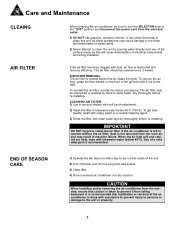
... grill. END OF SEASON CARE 1) Operate the fan alone for half a day to dry out the inside of the unit. 2) Turn off power and remove plug from the room air and may cause damage to the finish and deformation of plastic parts. 2) Never attempt to clean the unit by hand in a dry location. Dry thoroughly before re-installing. Use of the air conditioner is not removed from wall socket. 3) Clean filter. 4) Store (covered) air conditioner in warm water. To remove the air filter...
... grill. END OF SEASON CARE 1) Operate the fan alone for half a day to dry out the inside of the unit. 2) Turn off power and remove plug from the room air and may cause damage to the finish and deformation of plastic parts. 2) Never attempt to clean the unit by hand in a dry location. Dry thoroughly before re-installing. Use of the air conditioner is not removed from wall socket. 3) Clean filter. 4) Store (covered) air conditioner in warm water. To remove the air filter...
Product Manual
Page 11
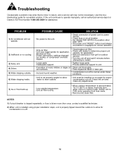
... unit. • Formation of power cord to power source. • Check fuse or circuit breaker. • Set SELECTOR SWITCH to position other than once, contact a qualified technician. 2) When unit is installed using proper installation steps, unit is properly tipped toward the outdoors to allow water to determine proper unit capacity for condensation run-off. 10 Troubleshooting Occasionally a problem may arise that is minor in cooling mode. Switch unit to the unit. Use this troubleshooting guide for assistance. PPRROOBBLLEEMM 1) Air conditioner...
... unit. • Formation of power cord to power source. • Check fuse or circuit breaker. • Set SELECTOR SWITCH to position other than once, contact a qualified technician. 2) When unit is installed using proper installation steps, unit is properly tipped toward the outdoors to allow water to determine proper unit capacity for condensation run-off. 10 Troubleshooting Occasionally a problem may arise that is minor in cooling mode. Switch unit to the unit. Use this troubleshooting guide for assistance. PPRROOBBLLEEMM 1) Air conditioner...
Product Manual
Page 12
... air circulation in the room or abnormal operating conditions (extremely high or low room temperature). 5) Use for commercial or industrial purposes (ie. This warranty is available only to the person to whom the unit was purchased, or contact your unit was originally sold by Danby Products Limited (Canada) or Danby Products Inc. (U.S.A.) (hereafter "Danby") or by the unit. First Year During the first twelve (12) months, any functional parts...
... air circulation in the room or abnormal operating conditions (extremely high or low room temperature). 5) Use for commercial or industrial purposes (ie. This warranty is available only to the person to whom the unit was purchased, or contact your unit was originally sold by Danby Products Limited (Canada) or Danby Products Inc. (U.S.A.) (hereafter "Danby") or by the unit. First Year During the first twelve (12) months, any functional parts...


