Product Manual
Page 14
D-Link Unified Access System Software User Manual 12/10/09 Section 5: Configuring Quality of Service 325 Configuring Differentiated Services ...326 Defining DiffServ...326 Diffserv Configuration ...326 ... CoS Interface Queue Configuration ...340 Configuring Auto VoIP ...342 Auto VoIP Configuration ...342 Section 6: Configuring Access Control Lists 344 IP Access Control Lists...345 IP ACL Configuration...345 IP ACL Rule Configuration ...346 MAC Access Control Lists ...351 MAC ACL Configuration ...351 MAC ACL Rule Configuration...352 ACL Interface Configuration ...355 Assigning an...
D-Link Unified Access System Software User Manual 12/10/09 Section 5: Configuring Quality of Service 325 Configuring Differentiated Services ...326 Defining DiffServ...326 Diffserv Configuration ...326 ... CoS Interface Queue Configuration ...340 Configuring Auto VoIP ...342 Auto VoIP Configuration ...342 Section 6: Configuring Access Control Lists 344 IP Access Control Lists...345 IP ACL Configuration...345 IP ACL Rule Configuration ...346 MAC Access Control Lists ...351 MAC ACL Configuration ...351 MAC ACL Rule Configuration...352 ACL Interface Configuration ...355 Assigning an...
Product Manual
Page 15
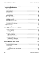
Software User Manual 12/10/09 D-Link Unified Access System Adding a Local User ...370 Configuring Users in the Local Database 371 Configuring Users in a Remote RADIUS Server 372 Interface Association...... Client Statistics...380 Viewing the Client Interface Association Status 381 Viewing the Client CP Association Status 382 SNMP Trap Configuration...382 Port Access Control...383 Global Port Access Control Configuration 384 Port Configuration ...385 Port Access Entity Capability Configuration 386 Supplicant Port Configuration ...387 User Login Configuration ...389 Port Access Privileges...
Software User Manual 12/10/09 D-Link Unified Access System Adding a Local User ...370 Configuring Users in the Local Database 371 Configuring Users in a Remote RADIUS Server 372 Interface Association...... Client Statistics...380 Viewing the Client Interface Association Status 381 Viewing the Client CP Association Status 382 SNMP Trap Configuration...382 Port Access Control...383 Global Port Access Control Configuration 384 Port Configuration ...385 Port Access Entity Capability Configuration 386 Supplicant Port Configuration ...387 User Login Configuration ...389 Port Access Privileges...
Product Manual
Page 19
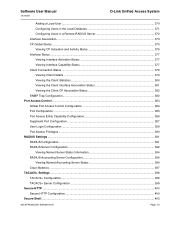
Software User Manual 12/10/09 D-Link Unified Access System WIDS Client Configuration ...527 Visualizing the Wireless Network ...529 Importing and Configuring a Background Image 530 Setting Up the Graph Components...the Graph ...538 Appendix A: Configuration Examples 539 Configuring VLANs ...539 Configuring Multiple Spanning Tree Protocol 542 Configuring VLAN Routing...545 Configuring 802.1X Network Access Control 548 Configuring a Virtual Access Point ...550 Configuring Differentiated Services for VoIP 554 Appendix B: Limited Warranty (USA Only 557 Product Registration...559 Appendix C: ...
Software User Manual 12/10/09 D-Link Unified Access System WIDS Client Configuration ...527 Visualizing the Wireless Network ...529 Importing and Configuring a Background Image 530 Setting Up the Graph Components...the Graph ...538 Appendix A: Configuration Examples 539 Configuring VLANs ...539 Configuring Multiple Spanning Tree Protocol 542 Configuring VLAN Routing...545 Configuring 802.1X Network Access Control 548 Configuring a Virtual Access Point ...550 Configuring Differentiated Services for VoIP 554 Appendix B: Limited Warranty (USA Only 557 Product Registration...559 Appendix C: ...
Product Manual
Page 28
...: PAE Capability Configuration ...387 Figure 275: Port Access Control Supplicant Port Configuration 387 Figure 276: Port Access Control Login ...389 Figure 277: Port Access Privileges ...390 Figure 278: RADIUS Configuration ...391 Page 28 Document 34CSFP6XXUWS-SWUM100-D7 Client Status ...381 Figure 270: CP - D-Link Unified Access System Software User Manual 12/10/09...
...: PAE Capability Configuration ...387 Figure 275: Port Access Control Supplicant Port Configuration 387 Figure 276: Port Access Control Login ...389 Figure 277: Port Access Privileges ...390 Figure 278: RADIUS Configuration ...391 Page 28 Document 34CSFP6XXUWS-SWUM100-D7 Client Status ...381 Figure 270: CP - D-Link Unified Access System Software User Manual 12/10/09...
Product Manual
Page 39
Client Status ...382 Table 241: SNMP Trap Configuration ...383 Table 242: Port Access Control-Port Configuration Fields 384 Table 243: Port Access Control Port Configuration Fields 385 Document 34CSFP6XXUWS-SWUM100-D7 Page 39 Software User Manual 12/10/09 D-Link Unified Access System Table 209: Policy Configuration Fields ...331 Table 210: Policy Class Definition...
Client Status ...382 Table 241: SNMP Trap Configuration ...383 Table 242: Port Access Control-Port Configuration Fields 384 Table 243: Port Access Control Port Configuration Fields 385 Document 34CSFP6XXUWS-SWUM100-D7 Page 39 Software User Manual 12/10/09 D-Link Unified Access System Table 209: Policy Configuration Fields ...331 Table 210: Policy Class Definition...
Product Manual
Page 40
D-Link Unified Access System Software User Manual 12/10/09 Table 244: PAE Capability Configuration...387 Table 245: Dot1x Supplicant Port Configuration 387 Table 246: Port Access Control user Login Configuration Fields 389 Table 247: Port Access Privileges Fields...390 Table 248: RADIUS Configuration Fields ...391 Table 249: RADIUS Server Configuration Fields 393...
D-Link Unified Access System Software User Manual 12/10/09 Table 244: PAE Capability Configuration...387 Table 245: Dot1x Supplicant Port Configuration 387 Table 246: Port Access Control user Login Configuration Fields 389 Table 247: Port Access Privileges Fields...390 Table 248: RADIUS Configuration Fields ...391 Table 249: RADIUS Server Configuration Fields 393...
Product Manual
Page 43
...configure the Differentiated Services, Class of Service, and Auto VoIP features. • Section 6: "Configuring Access Control Lists" on page 344 describes how to manage the D-Link software ACLs. • Section 7: "Managing Device Security" on page 359 contains information about configuring switch ... information such as captive portal configuration, port access control, TACACS+, and RADIUS server settings. • Section 8: "Configuring the Wireless Features" on page 405 describes how to configure selected features on the switch by using D-Link 4000 Series switch • Level 1 and/or...
...configure the Differentiated Services, Class of Service, and Auto VoIP features. • Section 6: "Configuring Access Control Lists" on page 344 describes how to manage the D-Link software ACLs. • Section 7: "Managing Device Security" on page 359 contains information about configuring switch ... information such as captive portal configuration, port access control, TACACS+, and RADIUS server settings. • Section 8: "Configuring the Wireless Features" on page 405 describes how to configure selected features on the switch by using D-Link 4000 Series switch • Level 1 and/or...
Product Manual
Page 45
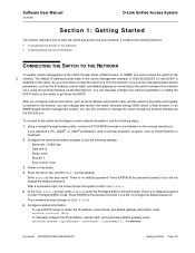
...prompt if you did not change the default password. After a successful login, the screen shows the system prompt(DWS-4026)>. 5 At the (DWS-4026)> prompt, enter enable to (DWS-4026)#. 6 Configure network information. - The command prompt changes to enter the Privileged EXEC command mode. After you ...a straight-through SSH, telnet, a Web browser, or an SNMP-based network management system. Flow control: none 3 Power on the switch. Software User Manual 12/10/09 D-Link Unified Access System Section 1: Getting Started This section describes how to obtain the IP address, subnet mask...
...prompt if you did not change the default password. After a successful login, the screen shows the system prompt(DWS-4026)>. 5 At the (DWS-4026)> prompt, enter enable to (DWS-4026)#. 6 Configure network information. - The command prompt changes to enter the Privileged EXEC command mode. After you ...a straight-through SSH, telnet, a Web browser, or an SNMP-based network management system. Flow control: none 3 Power on the switch. Software User Manual 12/10/09 D-Link Unified Access System Section 1: Getting Started This section describes how to obtain the IP address, subnet mask...
Product Manual
Page 60
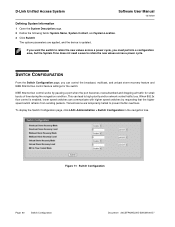
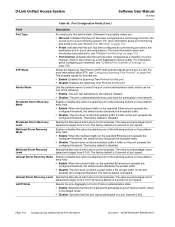
...from sending packets. When 802.3x flow control is updated. Transmissions are applied, and the device is enabled, lower speed switches can control the broadcast, multicast, and unicast storm recovery feature and IEEE 802.3x flow control feature settings for small bursts of time during... the congestion condition. To display the Switch Configuration page, click LAN >Administration > Switch Configuration in the navigation tree. This can lead to prevent buffer overflows. D-Link Unified Access System Software ...
...from sending packets. When 802.3x flow control is updated. Transmissions are applied, and the device is enabled, lower speed switches can control the broadcast, multicast, and unicast storm recovery feature and IEEE 802.3x flow control feature settings for small bursts of time during... the congestion condition. To display the Switch Configuration page, click LAN >Administration > Switch Configuration in the navigation tree. This can lead to prevent buffer overflows. D-Link Unified Access System Software ...
Product Manual
Page 61
...is disabled. • Enable: Enables flow control so that the switch can communicate with higher speed switches. • Disable: Disables flow control so that display when the slot contains a card. Software User Manual 12/10/09 D-Link Unified Access System Field Broadcast Storm Recovery Mode... Broadcast Storm Recovery Level Multicast Storm Recovery Mode Multicast Storm Recovery Level Unicast Storm Recovery Mode Unicast Storm Recovery Level IEEE 802.3x Flow Control Mode Table 6: Switch Configuration Fields...
...is disabled. • Enable: Enables flow control so that the switch can communicate with higher speed switches. • Disable: Disables flow control so that display when the slot contains a card. Software User Manual 12/10/09 D-Link Unified Access System Field Broadcast Storm Recovery Mode... Broadcast Storm Recovery Level Multicast Storm Recovery Mode Multicast Storm Recovery Level Unicast Storm Recovery Mode Unicast Storm Recovery Level IEEE 802.3x Flow Control Mode Table 6: Switch Configuration Fields...
Product Manual
Page 65
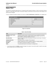
Figure 15: Serial Port Field Serial Port Login Timeout (minutes) Baud Rate (bps) Character Size (bits) Flow Control Stop Bits Parity Table 9: Serial Port Fields Description Indicates how many minutes of inactivity should occur on the switch, click LAN > Administration > Serial ... switch cannot be the same. Some settings on the serial port. Whether hardware flow control is 5. Its is always 8. Document 34CSFP6XXUWS-SWUM100-D7 Serial Port Page 65 Software User Manual 12/10/09 D-Link Unified Access System SERIAL PORT The Serial Port Configuration page allows you to change any ...
Figure 15: Serial Port Field Serial Port Login Timeout (minutes) Baud Rate (bps) Character Size (bits) Flow Control Stop Bits Parity Table 9: Serial Port Fields Description Indicates how many minutes of inactivity should occur on the switch, click LAN > Administration > Serial ... switch cannot be the same. Some settings on the serial port. Whether hardware flow control is 5. Its is always 8. Document 34CSFP6XXUWS-SWUM100-D7 Serial Port Page 65 Software User Manual 12/10/09 D-Link Unified Access System SERIAL PORT The Serial Port Configuration page allows you to change any ...
Product Manual
Page 67
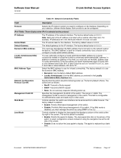
...Burned-in -band connectivity instead of the IP address must start with a colon between x'40' and x'7F'. Web Mode Java Mode Controls whether the switch user interface can optionally configure a locally administered MAC address for in MAC Address Locally Administered MAC Address This read -... Current Specify what the switch should do following power-up . The factory default value is 1-3965. Software User Manual 12/10/09 D-Link Unified Access System Table 10: Network Connectivity Fields Field Description Protocol Selects the IP protocol version you must also set to a 1 and ...
...Burned-in -band connectivity instead of the IP address must start with a colon between x'40' and x'7F'. Web Mode Java Mode Controls whether the switch user interface can optionally configure a locally administered MAC address for in MAC Address Locally Administered MAC Address This read -... Current Specify what the switch should do following power-up . The factory default value is 1-3965. Software User Manual 12/10/09 D-Link Unified Access System Table 10: Network Connectivity Fields Field Description Protocol Selects the IP protocol version you must also set to a 1 and ...
Product Manual
Page 74
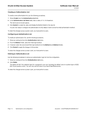
You are now ready to create the name and display the Method fields for system login or IEEE 802.1X port access control. You can only use this button if you must perform a save. Configuring an Authentication List To modify an authentication list, use the following ... the Authentication List Name field, enter a name of 1 to 12 characters. To retain the changes across a power cycle, you have Read/Write access. D-Link Unified Access System Software User Manual 12/10/09 Creating an Authentication List To create a new authentication list, use the following procedures to remove an...
You are now ready to create the name and display the Method fields for system login or IEEE 802.1X port access control. You can only use this button if you must perform a save. Configuring an Authentication List To modify an authentication list, use the following ... the Authentication List Name field, enter a name of 1 to 12 characters. To retain the changes across a power cycle, you have Read/Write access. D-Link Unified Access System Software User Manual 12/10/09 Creating an Authentication List To create a new authentication list, use the following procedures to remove an...
Product Manual
Page 75
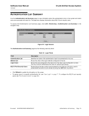
Shows the users assigned to this login list on page 77. Shows the port access control users assigned to this row. Figure 23: Login Session The Authentication List Summary page has the following read-only fields: Field Authentication List Method ...the information on the screen. • To assign users to a specific authentication list, see "Port Access Control" on the system and which users are associated with each list. Software User Manual 12/10/09 D-Link Unified Access System AUTHENTICATION LIST SUMMARY Use the Authentication List Summary page to view information about 802...
Shows the users assigned to this login list on page 77. Shows the port access control users assigned to this row. Figure 23: Login Session The Authentication List Summary page has the following read-only fields: Field Authentication List Method ...the information on the screen. • To assign users to a specific authentication list, see "Port Access Control" on the system and which users are associated with each list. Software User Manual 12/10/09 D-Link Unified Access System AUTHENTICATION LIST SUMMARY Use the Authentication List Summary page to view information about 802...
Product Manual
Page 78
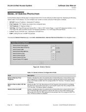
...smaller then configured value. • TCP Fragment: IP Fragment Offset = 1. • TCP Flag: TCP Flag SYN set and Source Port < 1024 or TCP Control Flags = 0 and TCP Sequence Number = 0 or TCP Flags FIN, URG, and PSH set and TCP Sequence Number = 0 or TCP Flags SYN and...selecting the corresponding line on the pulldown entry field. Enabling First Fragment DoS prevention causes the switch to configure DoS control. The factory default is disabled. D-Link software provides support for classifying and blocking specific types of Service Protection in the navigation menu. Page 78 Denial of...
...smaller then configured value. • TCP Fragment: IP Fragment Offset = 1. • TCP Flag: TCP Flag SYN set and Source Port < 1024 or TCP Control Flags = 0 and TCP Sequence Number = 0 or TCP Flags FIN, URG, and PSH set and TCP Sequence Number = 0 or TCP Flags SYN and...selecting the corresponding line on the pulldown entry field. Enabling First Fragment DoS prevention causes the switch to configure DoS control. The factory default is disabled. D-Link software provides support for classifying and blocking specific types of Service Protection in the navigation menu. Page 78 Denial of...
Product Manual
Page 79
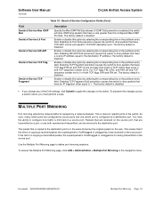
...UDP destination port. Enable or disable this option by a network analyzer. The factory default is disabled. Software User Manual 12/10/09 D-Link Unified Access System Table 19: Denial of Service Configuration Fields (Cont.) Field Denial of Service Max ICMP Size Denial of Service L4 Port ... is disabled. The factory default is enabled, the switch will drop ICMP ping packets that have a size greater than 1024 or TCP control flags set to 0 and TCP sequence number set to define port mirroring sessions. Enable or disable this option by selecting the corresponding line...
...UDP destination port. Enable or disable this option by a network analyzer. The factory default is disabled. Software User Manual 12/10/09 D-Link Unified Access System Table 19: Denial of Service Configuration Fields (Cont.) Field Denial of Service Max ICMP Size Denial of Service L4 Port ... is disabled. The factory default is enabled, the switch will drop ICMP ping packets that have a size greater than 1024 or TCP control flags set to 0 and TCP sequence number set to define port mirroring sessions. Enable or disable this option by selecting the corresponding line...
Product Manual
Page 86
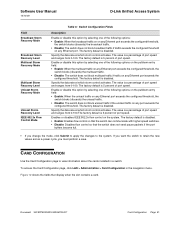
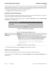
... click LAN > Administration > Log > Command Logger Configuration in thread id 2110. CONSOLE LOG CONFIGURATION Use the Console Log Configuration page to control logging to any serial device attached to log CLI commands in the system log file. • Enable: The system logs CLI commands. .... Figure 32: Command Logger Configuration Field Admin Mode Table 24: Command Logger Configuration Fields Description This field determines whether to the switch. D-Link Unified Access System Software User Manual 12/10/09 This log message has a severity level of 7 (15 mod 8), which IP address...
... click LAN > Administration > Log > Command Logger Configuration in thread id 2110. CONSOLE LOG CONFIGURATION Use the Console Log Configuration page to control logging to any serial device attached to log CLI commands in the system log file. • Enable: The system logs CLI commands. .... Figure 32: Command Logger Configuration Field Admin Mode Table 24: Command Logger Configuration Fields Description This field determines whether to the switch. D-Link Unified Access System Software User Manual 12/10/09 This log message has a severity level of 7 (15 mod 8), which IP address...
Product Manual
Page 93
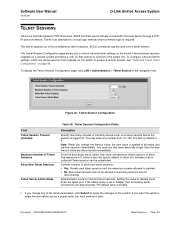
... Allow New Telnet Sessions Telnet Server Admin Mode Table 30: Telnet Session Configuration Fields Description Specify how many simultaneous telnet sessions to control inbound telnet settings on the switch. All CLI commands can be established. Figure 40: Telnet Session Configuration Field Telnet Session Timeout ... 34CSFP6XXUWS-SWUM100-D7 Telnet Sessions Page 93 If you want the switch to the switch CLI. Software User Manual 12/10/09 D-Link Unified Access System TELNET SESSIONS Telnet is 5. Telnet is an alternative to a local login terminal where a remote login is applied to...
... Allow New Telnet Sessions Telnet Server Admin Mode Table 30: Telnet Session Configuration Fields Description Specify how many simultaneous telnet sessions to control inbound telnet settings on the switch. All CLI commands can be established. Figure 40: Telnet Session Configuration Field Telnet Session Timeout ... 34CSFP6XXUWS-SWUM100-D7 Telnet Sessions Page 93 If you want the switch to the switch CLI. Software User Manual 12/10/09 D-Link Unified Access System TELNET SESSIONS Telnet is 5. Telnet is an alternative to a local login terminal where a remote login is applied to...
Product Manual
Page 94
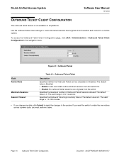
...retain the new values across a power cycle, you change any data, click Submit to apply the changes to a remote system. D-Link Unified Access System Software User Manual 12/10/09 OUTBOUND TELNET CLIENT CONFIGURATION The outbound telnet feature is not available on all platforms. Use... the outbound telnet client settings to control the telnet sessions that originate from the switch. To access the Outbound Telnet Client Configuration page, click LAN > Administration > Outbound Telnet...
...retain the new values across a power cycle, you change any data, click Submit to apply the changes to a remote system. D-Link Unified Access System Software User Manual 12/10/09 OUTBOUND TELNET CLIENT CONFIGURATION The outbound telnet feature is not available on all platforms. Use... the outbound telnet client settings to control the telnet sessions that originate from the switch. To access the Outbound Telnet Client Configuration page, click LAN > Administration > Outbound Telnet...
Product Manual
Page 110
... option by selecting one of port speed and ranges from 0-100. Selects the Link Aggregation Control Protocol administration state: • Enable: Specifies that the port is allowed to select the port control administration state, which is the default mode. • Disable: Specifies that the... port and is administratively down and does not participate in a port mirroring session. Specify the data rate at which storm control activates. The factory default is disabled. Multicast Storm Recovery Level Unicast Storm Recovery Mode Unicast Storm Recovery Level LACP Mode Specify...
... option by selecting one of port speed and ranges from 0-100. Selects the Link Aggregation Control Protocol administration state: • Enable: Specifies that the port is allowed to select the port control administration state, which is the default mode. • Disable: Specifies that the... port and is administratively down and does not participate in a port mirroring session. Specify the data rate at which storm control activates. The factory default is disabled. Multicast Storm Recovery Level Unicast Storm Recovery Mode Unicast Storm Recovery Level LACP Mode Specify...
