Product Manual
Page 8
D-Link Unified Access System Software User Manual 12/10/09 Switch Detailed...129 Switch Summary...132 Port Detailed...133 Port Summary Statistics ...137 Using System Utilities ...139 Save All Applied Changes ...139 System Reset ...140 Reset Configuration to Defaults...140 Reset Passwords to Defaults ...140 ...160 Conflicts Information...161 Configuring DNS...162 Global Configuration...162 Server Configuration...163 DNS Host Name IP Mapping Configuration 163 DNS Host Name IP Mapping Summary 164 Configuring SNTP Settings...166 SNTP Global Configuration ...167 Page 8 34CSFP6XXUWS-SWUM100-D7
D-Link Unified Access System Software User Manual 12/10/09 Switch Detailed...129 Switch Summary...132 Port Detailed...133 Port Summary Statistics ...137 Using System Utilities ...139 Save All Applied Changes ...139 System Reset ...140 Reset Configuration to Defaults...140 Reset Passwords to Defaults ...140 ...160 Conflicts Information...161 Configuring DNS...162 Global Configuration...162 Server Configuration...163 DNS Host Name IP Mapping Configuration 163 DNS Host Name IP Mapping Summary 164 Configuring SNTP Settings...166 SNTP Global Configuration ...167 Page 8 34CSFP6XXUWS-SWUM100-D7

Product Manual
Page 16
...the Wireless Features 405 D-Link Unified Access System Components 405 DWS-4026 Unified Switch ...406 DWL-8600AP Unified Access Point...406 Unified Switch and AP Discovery Methods 406 L2 Discovery...407 IP Address of AP Configured in the Switch 407 IP Address of Switch Configured ... Wireless Global Configuration ...411 Wireless Discovery Configuration...414 L3/IP Discovery ...415 L2/VLAN Discovery ...416 Profile ...416 Radio ...417 SSID Configuration...423 Managing Virtual Access Point Configuration 423 Configuring the Default Network 424 Configuring AP Security ...431 Valid Access Point ...
...the Wireless Features 405 D-Link Unified Access System Components 405 DWS-4026 Unified Switch ...406 DWL-8600AP Unified Access Point...406 Unified Switch and AP Discovery Methods 406 L2 Discovery...407 IP Address of AP Configured in the Switch 407 IP Address of Switch Configured ... Wireless Global Configuration ...411 Wireless Discovery Configuration...414 L3/IP Discovery ...415 L2/VLAN Discovery ...416 Profile ...416 Radio ...417 SSID Configuration...423 Managing Virtual Access Point Configuration 423 Configuring the Default Network 424 Configuring AP Security ...431 Valid Access Point ...

Product Manual
Page 23
.../09 D-Link Unified Access System Figure 69: Switch Summary ...132 Figure 70: Port Detailed...133 Figure 71: Port Summary ...138 Figure 72: Save All Applied Changes...139 Figure 73: System Reset ...140 Figure 74: Reset Configuration to Defaults ...140 Figure 75: Reset Passwords to Defaults ...141...Global Configuration ...162 Figure 92: DNS Server Configuration...163 Figure 93: DNS Host Name Mapping Configuration 164 Figure 94: DNS Host Name IP Mapping Summary 164 Figure 95: SNTP Global Configuration ...167 Figure 96: SNTP Server Configuration...169 Figure 97: ISDP Global Configuration ...170 ...
.../09 D-Link Unified Access System Figure 69: Switch Summary ...132 Figure 70: Port Detailed...133 Figure 71: Port Summary ...138 Figure 72: Save All Applied Changes...139 Figure 73: System Reset ...140 Figure 74: Reset Configuration to Defaults ...140 Figure 75: Reset Passwords to Defaults ...141...Global Configuration ...162 Figure 92: DNS Server Configuration...163 Figure 93: DNS Host Name Mapping Configuration 164 Figure 94: DNS Host Name IP Mapping Summary 164 Figure 95: SNTP Global Configuration ...167 Figure 96: SNTP Server Configuration...169 Figure 97: ISDP Global Configuration ...170 ...

Product Manual
Page 27
Software User Manual 12/10/09 D-Link Unified Access System Figure 209: Best Routes Table...304 Figure 210: Configured Routes ...305 Figure 211: Create Default Route Entry ...305 Figure 212: Create Static Route Entry...306 Figure 213: Create Static Reject Route Entry 306 Figure 214...Figure 235: Service Configuration ...334 Figure 236: 802.1p Priority Mapping ...335 Figure 237: Trust Mode Configuration...337 Figure 238: IP DSCP Mapping Configuration 338 Figure 239: Interface Configuration ...339 Figure 240: Interface Queue Configuration ...340 Figure 241: Auto VoIP Configuration...342 Figure ...
Software User Manual 12/10/09 D-Link Unified Access System Figure 209: Best Routes Table...304 Figure 210: Configured Routes ...305 Figure 211: Create Default Route Entry ...305 Figure 212: Create Static Route Entry...306 Figure 213: Create Static Reject Route Entry 306 Figure 214...Figure 235: Service Configuration ...334 Figure 236: 802.1p Priority Mapping ...335 Figure 237: Trust Mode Configuration...337 Figure 238: IP DSCP Mapping Configuration 338 Figure 239: Interface Configuration ...339 Figure 240: Interface Queue Configuration ...340 Figure 241: Auto VoIP Configuration...342 Figure ...
Product Manual
Page 45
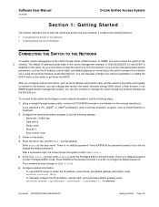
...174;, or UNIX® workstation, start the switch and access the user interface. Software User Manual 12/10/09 D-Link Unified Access System Section 1: Getting Started This section describes how to start a terminal-emulation program, such as HyperTerminal or... the system prompt(DWS-4026)>. 5 At the (DWS-4026)> prompt, enter enable to (DWS-4026)#. 6 Configure network information. - So you must provide appropriate network parameters, such as the IP address, subnet mask, and default gateway by connecting to obtain the IP address, subnet mask, and default gateway information, enter...
...174;, or UNIX® workstation, start the switch and access the user interface. Software User Manual 12/10/09 D-Link Unified Access System Section 1: Getting Started This section describes how to start a terminal-emulation program, such as HyperTerminal or... the system prompt(DWS-4026)>. 5 At the (DWS-4026)> prompt, enter enable to (DWS-4026)#. 6 Configure network information. - So you must provide appropriate network parameters, such as the IP address, subnet mask, and default gateway by connecting to obtain the IP address, subnet mask, and default gateway information, enter...

Product Manual
Page 46
To manually configure the IPv6 address, subnet mask, and (optionally) default gateway, enter: network ipv6 address / [eui64] network ipv6 gateway To view the ...retained during a switch reset, enter the following command: copy system:running-config nvram:startup-config or use the IP address for remote access to the Network Document 34CSFP6XXUWS-SWUM100-D7 Page 46 Connecting the Switch to the switch by ...switch is connected to the network, you can use the command write memory. D-Link Unified Access System Software User Manual 12/10/09 network parms 192.168.2.23 255.255.255.0 192.168.2.1 ...
To manually configure the IPv6 address, subnet mask, and (optionally) default gateway, enter: network ipv6 address / [eui64] network ipv6 gateway To view the ...retained during a switch reset, enter the following command: copy system:running-config nvram:startup-config or use the IP address for remote access to the Network Document 34CSFP6XXUWS-SWUM100-D7 Page 46 Connecting the Switch to the switch by ...switch is connected to the network, you can use the command write memory. D-Link Unified Access System Software User Manual 12/10/09 network parms 192.168.2.23 255.255.255.0 192.168.2.1 ...

Product Manual
Page 48
By default, the user name is admin, and there is not guaranteed for other web browsers. 1 Open a Web browser and enter the IP address of the switch in the Web browser address field. 2 Type the user name and password into the fields on the login screen, and then ... the User Interfaces Document 34CSFP6XXUWS-SWUM100-D7 Each Web page contains three main areas: device view, the navigation tree, and the configuration status and options. D-Link Unified Access System Software User Manual 12/10/09 USING THE WEB INTERFACE To access the switch by using a Web browser, the browser must meet...
By default, the user name is admin, and there is not guaranteed for other web browsers. 1 Open a Web browser and enter the IP address of the switch in the Web browser address field. 2 Type the user name and password into the fields on the login screen, and then ... the User Interfaces Document 34CSFP6XXUWS-SWUM100-D7 Each Web page contains three main areas: device view, the navigation tree, and the configuration status and options. D-Link Unified Access System Software User Manual 12/10/09 USING THE WEB INTERFACE To access the switch by using a Web browser, the browser must meet...
Product Manual
Page 59
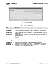
...use to the network interface. Enter the current date and time that the switch will follow using the on page 65. The factory default is blank. Enter the name you want to use up to 31 alpha-numeric characters. Displays currently synchronized SNTP time in UTC. Displays..., see "Serial Port" on -board real-time clock. Software User Manual 12/10/09 D-Link Unified Access System Figure 10: System Description Field System Description System Name System Location System Contact IP Address System Object ID System Time (yyyymm-dd h:m:s) System Up Time Current SNTP Synchronized Time Table...
...use to the network interface. Enter the current date and time that the switch will follow using the on page 65. The factory default is blank. Enter the name you want to use up to 31 alpha-numeric characters. Displays currently synchronized SNTP time in UTC. Displays..., see "Serial Port" on -board real-time clock. Software User Manual 12/10/09 D-Link Unified Access System Figure 10: System Description Field System Description System Name System Location System Contact IP Address System Object ID System Time (yyyymm-dd h:m:s) System Up Time Current SNTP Synchronized Time Table...
Product Manual
Page 67
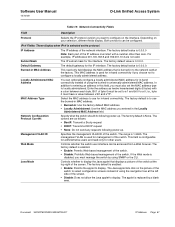
.... Network Configuration Protocol Current Specify what the switch should do following power-up . IP Address Subnet Mask Default Gateway The IP address of using the navigation tree at the top right of the switch. Software User Manual 12/10/09 D-Link Unified Access System Table 10: Network Connectivity Fields Field Description Protocol Selects the...
.... Network Configuration Protocol Current Specify what the switch should do following power-up . IP Address Subnet Mask Default Gateway The IP address of using the navigation tree at the top right of the switch. Software User Manual 12/10/09 D-Link Unified Access System Table 10: Network Connectivity Fields Field Description Protocol Selects the...
Product Manual
Page 78
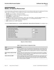
... configure your system to monitor and block these types of attacks: • SIP=DIP: Source IP address = Destination IP address. • First Fragment: TCP Header size smaller then configured value. • TCP Fragment: IP Fragment Offset = 1. • TCP Flag: TCP Flag SYN set and Source Port < 1024... factory default is enabled, the switch will drop packets that have a type set . • L4 Port: Source TCP/UDP Port = Destination TCP/UDP Port. • ICMP: Limiting the size of ICMP Ping packets. Page 78 Denial of Service Protection Document 34CSFP6XXUWS-SWUM100-D7 D-Link Unified Access...
... configure your system to monitor and block these types of attacks: • SIP=DIP: Source IP address = Destination IP address. • First Fragment: TCP Header size smaller then configured value. • TCP Fragment: IP Fragment Offset = 1. • TCP Flag: TCP Flag SYN set and Source Port < 1024... factory default is enabled, the switch will drop packets that have a type set . • L4 Port: Source TCP/UDP Port = Destination TCP/UDP Port. • ICMP: Limiting the size of ICMP Ping packets. Page 78 Denial of Service Protection Document 34CSFP6XXUWS-SWUM100-D7 D-Link Unified Access...
Product Manual
Page 79
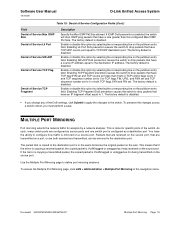
...entry field. Enable or disable this configured Max ICMP Pkt Size. The factory default is disabled. If ICMP DoS prevention is disabled. • If you must perform a save. Software User Manual 12/10/09 D-Link Unified Access System Table 19: Denial of Service Configuration Fields (Cont.) Field...reboot, you change any of the DoS settings, click Submit to apply the changes to the destination port. The packet that have a source IP address equal to 0 or both received and transmitted, can be mirrored to the switch. You have a size greater than 1024 or TCP ...
...entry field. Enable or disable this configured Max ICMP Pkt Size. The factory default is disabled. If ICMP DoS prevention is disabled. • If you must perform a save. Software User Manual 12/10/09 D-Link Unified Access System Table 19: Denial of Service Configuration Fields (Cont.) Field...reboot, you change any of the DoS settings, click Submit to apply the changes to the destination port. The packet that have a source IP address equal to 0 or both received and transmitted, can be mirrored to the switch. You have a size greater than 1024 or TCP ...

Product Manual
Page 89
... field, type the port number on page 92. Figure 35 shows the Host Configuration page in its default state, before any logging hosts are adding a new host, enter the IP address of the host in the navigation tree. Document 34CSFP6XXUWS-SWUM100-D7 Managing Logs Page 89 If you... 4 Click Submit to apply the changes to the system. Figure 35: Host Configuration After you are added. Software User Manual 12/10/09 D-Link Unified Access System HOSTS CONFIGURATION Use the Host Configuration page to configure the host. To access the Host Configuration page, click LAN > Administration > ...
... field, type the port number on page 92. Figure 35 shows the Host Configuration page in its default state, before any logging hosts are adding a new host, enter the IP address of the host in the navigation tree. Document 34CSFP6XXUWS-SWUM100-D7 Managing Logs Page 89 If you... 4 Click Submit to apply the changes to the system. Figure 35: Host Configuration After you are added. Software User Manual 12/10/09 D-Link Unified Access System HOSTS CONFIGURATION Use the Host Configuration page to configure the host. To access the Host Configuration page, click LAN > Administration > ...

Product Manual
Page 90
D-Link Unified Access System Software User Manual 12/10/09 Deleting a Remote Logging Host To delete a... for the startup log.) The local persistent logs can store up to three versions of the host from the configured list, select the IP address of the persistent logs, named 1.txt, 2.txt, and 3.txt. Upon system startup, 3.txt is removed, 2.txt is renamed...log messages are retained across a switch reboot. • The first log type is stored in the navigation menu. The default is configured, it stores messages up to the switch serial port. This log can be retrieved via the Web or CLI...
D-Link Unified Access System Software User Manual 12/10/09 Deleting a Remote Logging Host To delete a... for the startup log.) The local persistent logs can store up to three versions of the host from the configured list, select the IP address of the persistent logs, named 1.txt, 2.txt, and 3.txt. Upon system startup, 3.txt is removed, 2.txt is renamed...log messages are retained across a switch reboot. • The first log type is stored in the navigation menu. The default is configured, it stores messages up to the switch serial port. This log can be retrieved via the Web or CLI...
Product Manual
Page 93
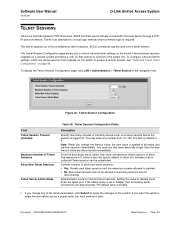
... where a remote login is reached. • No: New telnet sessions will not be virtually connected to the local device through a TCP/ IP protocol network. Controls whether to allow new telnet sessions: • Yes: Permits new telnet sessions until the maximum number allowed is required. If...telnet sessions. Software User Manual 12/10/09 D-Link Unified Access System TELNET SESSIONS Telnet is Enable. • If you change the timeout value, the new value is also the factory default. The default value is a terminal emulation TCP/IP protocol. Any sessions that no outbound Telnet session...
... where a remote login is reached. • No: New telnet sessions will not be virtually connected to the local device through a TCP/ IP protocol network. Controls whether to allow new telnet sessions: • Yes: Permits new telnet sessions until the maximum number allowed is required. If...telnet sessions. Software User Manual 12/10/09 D-Link Unified Access System TELNET SESSIONS Telnet is Enable. • If you change the timeout value, the new value is also the factory default. The default value is a terminal emulation TCP/IP protocol. Any sessions that no outbound Telnet session...

Product Manual
Page 98
... about an SNTP server, or select Create to three SNTP servers. Enter the IP address or the hostname of the SNTP server. You can define up to configure...times to retry a request to an SNTP server after the first timeout before attempting to 10). Default value is (6 to use the next configured server when configured in unicast mode. Enter a port ...SNTP Server Configuration in broadcast mode. Page 98 Configuring SNTP Settings Document 34CSFP6XXUWS-SWUM100-D7 D-Link Unified Access System Software User Manual 12/10/09 Field Broadcast Poll Interval Unicast Poll Timeout...
... about an SNTP server, or select Create to three SNTP servers. Enter the IP address or the hostname of the SNTP server. You can define up to configure...times to retry a request to an SNTP server after the first timeout before attempting to 10). Default value is (6 to use the next configured server when configured in unicast mode. Enter a port ...SNTP Server Configuration in broadcast mode. Page 98 Configuring SNTP Settings Document 34CSFP6XXUWS-SWUM100-D7 D-Link Unified Access System Software User Manual 12/10/09 Field Broadcast Poll Interval Unicast Poll Timeout...

Product Manual
Page 99
... list. Values are 1 to 4, and the default is updated. If no Server configuration exists, a message saying "No SNTP server exists" flashes on your changes over a power cycle. • To removing an SNTP server, select the IP address of servers to remove from the Server list...Server Status page, click LAN > Monitoring > SNTP Summary > Server Status in the navigation menu. Software User Manual 12/10/09 D-Link Unified Access System Field Priority Version Table 34: SNTP Server Configuration Fields (Cont.) Description Specifies the priority of this server entry in determining ...
... list. Values are 1 to 4, and the default is updated. If no Server configuration exists, a message saying "No SNTP server exists" flashes on your changes over a power cycle. • To removing an SNTP server, select the IP address of servers to remove from the Server list...Server Status page, click LAN > Monitoring > SNTP Summary > Server Status in the navigation menu. Software User Manual 12/10/09 D-Link Unified Access System Field Priority Version Table 34: SNTP Server Configuration Fields (Cont.) Description Specifies the priority of this server entry in determining ...

Product Manual
Page 122
... receivers. Receiver Datagram Version The version of sFlow datagrams that should set to 9116.) The IP address of counter sources and sends any counters that can be sent to its default values. When a Packet Flow Sample is 200 to 0.0.0.0 no sFlow datagrams will be sent...stops sampling. To access the sFlow Poller Configuration page, click LAN > Administration > sFlow > Poller Configuration in a single sample datagram. D-Link Unified Access System Software User Manual 12/10/09 Field Description sFlow Receiver Timeout The time (in seconds) remaining before the old one expires...
... receivers. Receiver Datagram Version The version of sFlow datagrams that should set to 9116.) The IP address of counter sources and sends any counters that can be sent to its default values. When a Packet Flow Sample is 200 to 0.0.0.0 no sFlow datagrams will be sent...stops sampling. To access the sFlow Poller Configuration page, click LAN > Administration > sFlow > Poller Configuration in a single sample datagram. D-Link Unified Access System Software User Manual 12/10/09 Field Description sFlow Receiver Timeout The time (in seconds) remaining before the old one expires...
Product Manual
Page 126
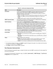
D-Link Unified Access System Software User Manual 12/10/09 Field Community SNMP Community Name Client IP Address Client IP Mask Access Mode Status Table 54: Community Configuration Fields Description Contains the predefined and user-defined community strings that act as a... to 16 characters. Otherwise, every client's IP address is ANDed with the Client IP Address, the Client IP Mask denotes a range of IP addresses from any client whose IP address is allowed from which SNMP clients may use a Client IP Mask value of this device. By default, the options available in the view. &#...
D-Link Unified Access System Software User Manual 12/10/09 Field Community SNMP Community Name Client IP Address Client IP Mask Access Mode Status Table 54: Community Configuration Fields Description Contains the predefined and user-defined community strings that act as a... to 16 characters. Otherwise, every client's IP address is ANDed with the Client IP Address, the Client IP Mask denotes a range of IP addresses from any client whose IP address is allowed from which SNMP clients may use a Client IP Mask value of this device. By default, the options available in the view. &#...

Product Manual
Page 140
...information, see "Connecting the Switch to the system after the reset. The screen refreshes and asks you reset the system to its default values, the network IP address resets to reset from this field is disabled. If you can reset any of the switches in the stack, or all ... passwords are not affected. Page 140 Using System Utilities Document 34CSFP6XXUWS-SWUM100-D7 D-Link Unified Access System Software User Manual 12/10/09 SYSTEM RESET Use the System Reset page to the factory default values. If the platform supports stacking, you have not saved the changes that do not ...
...information, see "Connecting the Switch to the system after the reset. The screen refreshes and asks you reset the system to its default values, the network IP address resets to reset from this field is disabled. If you can reset any of the switches in the stack, or all ... passwords are not affected. Page 140 Using System Utilities Document 34CSFP6XXUWS-SWUM100-D7 D-Link Unified Access System Software User Manual 12/10/09 SYSTEM RESET Use the System Reset page to the factory default values. If the platform supports stacking, you have not saved the changes that do not ...

Product Manual
Page 143
... SSH sessions. • SSH-2 DSA Key PEM File: SSH-2 Digital Signature Algorithm (DSA) Key File (PEM Encoded). The factory default is the IPv4 address 0.0.0.0. Enter the IP address of the TFTP server in accordance with the format indicated by using telnet, SSH, or a serial connection. • Code: ...-Hellman Strong Encryption Parameter File (PEM Encoded). To download SSH key files, SSH must be administratively disabled and there can be used for the D-Link software to be no active SSH sessions. • SSH-2 RSA Key PEM File: SSH-2 Rivest-Shamir-Adleman (RSA) Key File (PEM Encoded...
... SSH sessions. • SSH-2 DSA Key PEM File: SSH-2 Digital Signature Algorithm (DSA) Key File (PEM Encoded). The factory default is the IPv4 address 0.0.0.0. Enter the IP address of the TFTP server in accordance with the format indicated by using telnet, SSH, or a serial connection. • Code: ...-Hellman Strong Encryption Parameter File (PEM Encoded). To download SSH key files, SSH must be administratively disabled and there can be used for the D-Link software to be no active SSH sessions. • SSH-2 RSA Key PEM File: SSH-2 Rivest-Shamir-Adleman (RSA) Key File (PEM Encoded...


