User Guide
Page 7
... networking in this manual will refer to the DSS-24 10/100 Auto Negotiation Switch as the DSS-24. Appendix A, DSS-24 Technical Specifications, covers the technical specifications of the DSS-24. Refer to other D-Link products is contained in general. Chapter 6, Troubleshooting, covers troubleshooting the DSS-24. Audience This user guide is installing the DSS-24 on a network. All the information you need to...
... networking in this manual will refer to the DSS-24 10/100 Auto Negotiation Switch as the DSS-24. Appendix A, DSS-24 Technical Specifications, covers the technical specifications of the DSS-24. Refer to other D-Link products is contained in general. Chapter 6, Troubleshooting, covers troubleshooting the DSS-24. Audience This user guide is installing the DSS-24 on a network. All the information you need to...
User Guide
Page 8
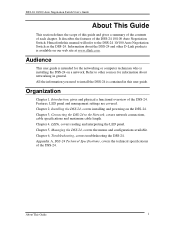
...3V. • RS-232 console port allows user to switch between 10 Mbps and 100 Mbps. DSS-24 10/100 Auto Negotiation Switch User's Guide 1 Introduction This chapter gives a physical and functional overview of the DSS-24. The DSS-24 can be dealt with polarity detection and correcting. •...; Wire speed packet filtering and forwarding. • Per port LED to indicate link, ...
...3V. • RS-232 console port allows user to switch between 10 Mbps and 100 Mbps. DSS-24 10/100 Auto Negotiation Switch User's Guide 1 Introduction This chapter gives a physical and functional overview of the DSS-24. The DSS-24 can be dealt with polarity detection and correcting. •...; Wire speed packet filtering and forwarding. • Per port LED to indicate link, ...
User Guide
Page 9
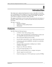
.... It is not necessary to connect to the DSS-24 in order to monitor performance at a glance. Power Link/ Act/ Collision LEDS MDI-II Uplink Port MDI-X Ports DSS-24 Power 10/100 Fast Ethernet Switch Switch II Link/ 100 Mbps/ Collision 10 Mbps 1 234 56 7 9 10 11 12 Link/ 100 Mbps/ D-Link Collision 10 Mbps 13 14 15 17 18 19 21 22...
.... It is not necessary to connect to the DSS-24 in order to monitor performance at a glance. Power Link/ Act/ Collision LEDS MDI-II Uplink Port MDI-X Ports DSS-24 Power 10/100 Fast Ethernet Switch Switch II Link/ 100 Mbps/ Collision 10 Mbps 1 234 56 7 9 10 11 12 Link/ 100 Mbps/ D-Link Collision 10 Mbps 13 14 15 17 18 19 21 22...
User Guide
Page 10
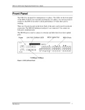
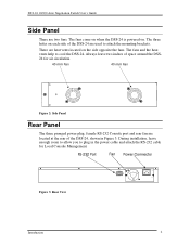
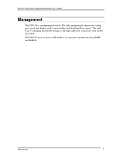
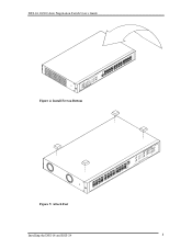
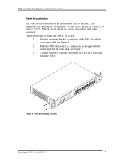
Always leave two inches of space around the DSS24 for Local Console Management. DSS-24 10/100 Auto Negotiation Switch User's Guide Side Panel There are located at the rear of the DSS-24, shown in the power cable and attach the RS-232 cable for air circulation. 40 mm Fan 40 mm Fan Figure 2: ... Panel The three pronged power plug, female RS-232 Console port and rear fan are two fans. The three holes on each side of the DSS-24 are heat vents located on . RS-232 Port Fan Power Connector Figure 3: Rear View Introduction 4 During installation, leave enough room to allow you ...
Always leave two inches of space around the DSS24 for Local Console Management. DSS-24 10/100 Auto Negotiation Switch User's Guide Side Panel There are located at the rear of the DSS-24, shown in the power cable and attach the RS-232 cable for air circulation. 40 mm Fan 40 mm Fan Figure 2: ... Panel The three pronged power plug, female RS-232 Console port and rear fan are two fans. The three holes on each side of the DSS-24 are heat vents located on . RS-232 Port Fan Power Connector Figure 3: Rear View Introduction 4 During installation, leave enough room to allow you ...
User Guide
Page 11
The only way of changing the default settings is an unmanaged switch. Introduction 5 It can not be monitored using SNMP and RMON. The DSS-24 does not have an IP address. DSS-24 10/100 Auto Negotiation Switch User's Guide Management The DSS-24 is through a physical connection with an RS232 cable. The only management options are setting port speed and duplex mode, and enabling and disabling flow control.
The only way of changing the default settings is an unmanaged switch. Introduction 5 It can not be monitored using SNMP and RMON. The DSS-24 does not have an IP address. DSS-24 10/100 Auto Negotiation Switch User's Guide Management The DSS-24 is through a physical connection with an RS232 cable. The only management options are setting port speed and duplex mode, and enabling and disabling flow control.
User Guide
Page 12
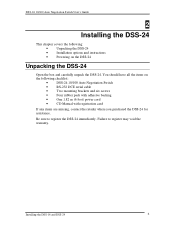
... items on the DSS-24 Unpacking the DSS-24 Open the box and carefully unpack the DSS-24. Be sure to register may void the warranty. DSS-24 10/100 Auto Negotiation Switch User's Guide 2 Installing the DSS-24 This chapter covers the following: • Unpacking the DSS-24 • Installation options and instructions • Powering on the following checklist: • DSS-24 10/100 Auto Negotiation...
... items on the DSS-24 Unpacking the DSS-24 Open the box and carefully unpack the DSS-24. Be sure to register may void the warranty. DSS-24 10/100 Auto Negotiation Switch User's Guide 2 Installing the DSS-24 This chapter covers the following: • Unpacking the DSS-24 • Installation options and instructions • Powering on the following checklist: • DSS-24 10/100 Auto Negotiation...
User Guide
Page 13
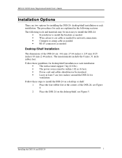
... the four rubber feet at least 5 cm (two inches) around the DSS-24 for network connections. • Crimpers to install the DSS-24 on the desktop/shelf, see Figure 4. 2. Place the DSS-24 on a desktop or shelf: 1. Installing the DSS-16 and DSS-24 7 DSS-24 10/100 Auto Negotiation Switch User's Guide Installation Options There are two options for each are : 441...
... the four rubber feet at least 5 cm (two inches) around the DSS-24 for network connections. • Crimpers to install the DSS-24 on the desktop/shelf, see Figure 4. 2. Place the DSS-24 on a desktop or shelf: 1. Installing the DSS-16 and DSS-24 7 DSS-24 10/100 Auto Negotiation Switch User's Guide Installation Options There are two options for each are : 441...
User Guide
Page 14
DSS-24 10/100 Auto Negotiation Switch User's Guide Figure 4: Install Feet on Bottom Figure 5: Attach Feet Installing the DSS-16 and DSS-24 8
DSS-24 10/100 Auto Negotiation Switch User's Guide Figure 4: Install Feet on Bottom Figure 5: Attach Feet Installing the DSS-16 and DSS-24 8
User Guide
Page 15
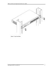
..., see Figure 6. 2. Attach a mounting bracket to each side of the DSS-24 with other equipment. Figure 6: Attach Mounting Brackets Installing the DSS-16 and DSS-24 9 DSS-24 can be placed in an EIA standard size 19 inch rack. DSS-24 10/100 Auto Negotiation Switch User's Guide Rack Installation The DSS-24 can be mounted in a wiring closet along with the screws...
..., see Figure 6. 2. Attach a mounting bracket to each side of the DSS-24 with other equipment. Figure 6: Attach Mounting Brackets Installing the DSS-16 and DSS-24 9 DSS-24 can be placed in an EIA standard size 19 inch rack. DSS-24 10/100 Auto Negotiation Switch User's Guide Rack Installation The DSS-24 can be mounted in a wiring closet along with the screws...
User Guide
Page 16
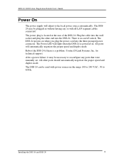
DSS-24 10/100 Auto Negotiation Switch User's Guide Figure 7: Insert into Rack Installing the DSS-16 and DSS-24 10
DSS-24 10/100 Auto Negotiation Switch User's Guide Figure 7: Insert into Rack Installing the DSS-16 and DSS-24 10
User Guide
Page 17
... on. All other end into the three pronged power connector. The DSS-24 powers on /off switch. After a power failure, it may be plugged in the range 100 to 240 VAC., 50 to 60 Hz. DSS-24 10/100 Auto Negotiation Switch User's Guide Power On The power supply will adjust to reconfigure any... or with all LAN segment cables connected. There is located at the rear of the DSS-24. Contact D-Link Systems, Inc. The DSS-24 can be necessary to the local power...
... on. All other end into the three pronged power connector. The DSS-24 powers on /off switch. After a power failure, it may be plugged in the range 100 to 240 VAC., 50 to 60 Hz. DSS-24 10/100 Auto Negotiation Switch User's Guide Power On The power supply will adjust to reconfigure any... or with all LAN segment cables connected. There is located at the rear of the DSS-24. Contact D-Link Systems, Inc. The DSS-24 can be necessary to the local power...
User Guide
Page 18
... Fast Ethernet networks is extremely important that cables have the correct pin arrangement and that the proper cables be arranged correctly inside the sheath. DSS-24 10/100 Auto Negotiation Switch User's Guide 3 Network Connections This chapter covers the following guidelines when handling cables: • Do not stretch or bend cables. • Do not...
... Fast Ethernet networks is extremely important that cables have the correct pin arrangement and that the proper cables be arranged correctly inside the sheath. DSS-24 10/100 Auto Negotiation Switch User's Guide 3 Network Connections This chapter covers the following guidelines when handling cables: • Do not stretch or bend cables. • Do not...
User Guide
Page 19
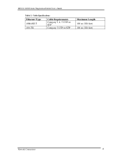
DSS-24 10/100 Auto Negotiation Switch User's Guide Table 1: Cable Specifications Ethernet Type 10BASE-T 100-TX Cable Requirements Category 3, 4, 5 UTP or STP Category 5 UTP or STP Maximum Length 100 m (328 feet) 100 m (328 feet) Network Connections 13
DSS-24 10/100 Auto Negotiation Switch User's Guide Table 1: Cable Specifications Ethernet Type 10BASE-T 100-TX Cable Requirements Category 3, 4, 5 UTP or STP Category 5 UTP or STP Maximum Length 100 m (328 feet) 100 m (328 feet) Network Connections 13
User Guide
Page 20
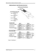
DSS-24 10/100 Auto Negotiation Switch User's Guide Figure 8: Cable Diagram Network Connections 14
DSS-24 10/100 Auto Negotiation Switch User's Guide Figure 8: Cable Diagram Network Connections 14
User Guide
Page 21
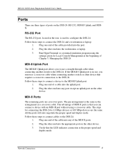
... cable. Follow these steps to connect cables to use a crossover cable when connecting another switch to 10 Mbps devices or 100 Mbps devices are the same. The pin arrangement is used to the DSS-24. Run HyperTerminal or a terminal emulation program using a crossover cable. Plug the other device... MDI-X ports. 2. Plug one end of a cable into any port except an uplink port on the DSS-24: RS-232, MDI-II Uplink, and MDIX. DSS-24 10/100 Auto Negotiation Switch User's Guide Ports There are crossover ports. Plug one end of the cable provided into the workstation or ...
... cable. Follow these steps to connect cables to use a crossover cable when connecting another switch to 10 Mbps devices or 100 Mbps devices are the same. The pin arrangement is used to the DSS-24. Run HyperTerminal or a terminal emulation program using a crossover cable. Plug the other device... MDI-X ports. 2. Plug one end of a cable into any port except an uplink port on the DSS-24: RS-232, MDI-II Uplink, and MDIX. DSS-24 10/100 Auto Negotiation Switch User's Guide Ports There are crossover ports. Plug one end of the cable provided into the workstation or ...
User Guide
Page 22
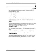
... when the port is powered on and dark when it is getting adequate power. DSS-24 10/100 Auto Negotiation Switch User's Guide 4 LEDs The LED panel of the DSS-24, displayed in detail. Flashing yellow indicates collisions are described in Figure 9, is linked up. See Table 2: Per Port LEDs, to give you critical information at the...
... when the port is powered on and dark when it is getting adequate power. DSS-24 10/100 Auto Negotiation Switch User's Guide 4 LEDs The LED panel of the DSS-24, displayed in detail. Flashing yellow indicates collisions are described in Figure 9, is linked up. See Table 2: Per Port LEDs, to give you critical information at the...
User Guide
Page 23
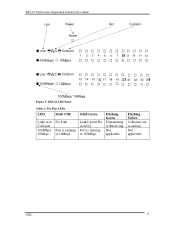
DSS-24 10/100 Auto Negotiation Switch User's Guide Link Power Power Act Collision Link/ 100Mbps/ Collision 10Mbps 1 234 56 7 9 10 11 12 Link/ 100Mbps/ Collision 10Mbps 13 14 15 17 18 19 21 22 23 100Mbps/ 10Mbps Figure 9: DSS-24 LED Panel Table 2: Per Port LEDs LED Dark (Off) Link/ Act/ Collision 100Mbps/ 10Mbps No Link Port is running at 10Mbps Solid Green Link Up but No Activity Port is running at 100Mbps Flashing Green Transmitting or Receiving Not applicable Flashing Yellow Collisions are occurring Not applicable LEDs 17
DSS-24 10/100 Auto Negotiation Switch User's Guide Link Power Power Act Collision Link/ 100Mbps/ Collision 10Mbps 1 234 56 7 9 10 11 12 Link/ 100Mbps/ Collision 10Mbps 13 14 15 17 18 19 21 22 23 100Mbps/ 10Mbps Figure 9: DSS-24 LED Panel Table 2: Per Port LEDs LED Dark (Off) Link/ Act/ Collision 100Mbps/ 10Mbps No Link Port is running at 10Mbps Solid Green Link Up but No Activity Port is running at 100Mbps Flashing Green Transmitting or Receiving Not applicable Flashing Yellow Collisions are occurring Not applicable LEDs 17
User Guide
Page 24
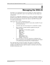
...; Flow Control: None • Enable: Terminal keys 4. Press Enter to reestablish the connection. This setting cannot be changed or disabled. Managing the DSS-24 18 The DSS24 is to connect a workstation or laptop to change two values: the physical state of the ports and the flow control. Press Enter...RS-232 serial port located at the rear. 2. If you have not done anything on after five minutes. DSS-24 10/100 Auto Negotiation Switch User's Guide 5 Managing the DSS-24 The DSS-24 is established. You can make any other end to the serial port of an RS-232 serial cable to ...
...; Flow Control: None • Enable: Terminal keys 4. Press Enter to reestablish the connection. This setting cannot be changed or disabled. Managing the DSS-24 18 The DSS24 is to connect a workstation or laptop to change two values: the physical state of the ports and the flow control. Press Enter...RS-232 serial port located at the rear. 2. If you have not done anything on after five minutes. DSS-24 10/100 Auto Negotiation Switch User's Guide 5 Managing the DSS-24 The DSS-24 is established. You can make any other end to the serial port of an RS-232 serial cable to ...
User Guide
Page 25
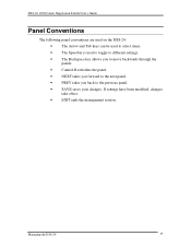
... If settings have been modified, changes take effect. • EXIT ends the management session. DSS-24 10/100 Auto Negotiation Switch User's Guide Panel Conventions The following panel conventions are used on the DSS-24: • The Arrow and Tab keys can be used to select items. • The Spacebar is used to toggle to different...
... If settings have been modified, changes take effect. • EXIT ends the management session. DSS-24 10/100 Auto Negotiation Switch User's Guide Panel Conventions The following panel conventions are used on the DSS-24: • The Arrow and Tab keys can be used to select items. • The Spacebar is used to toggle to different...
User Guide
Page 26
... ports have devices connected to other menus or panels available. Link Status The Link Status indicates whether the link to them will always show a Link Status of Link Down. Each panel has four columns: Port, Physical, Flow Control and Link Status. If you are numbered on ports in one are ... In forced mode Flow Control is the default port state. Leaving flow control enabled allows the port to any other device. DSS-24 10/100 Auto Negotiation Switch User's Guide Panels Each panel of the port. Port Port indicates the port number. The ports are using the uplink port,...
... ports have devices connected to other menus or panels available. Link Status The Link Status indicates whether the link to them will always show a Link Status of Link Down. Each panel has four columns: Port, Physical, Flow Control and Link Status. If you are numbered on ports in one are ... In forced mode Flow Control is the default port state. Leaving flow control enabled allows the port to any other device. DSS-24 10/100 Auto Negotiation Switch User's Guide Panels Each panel of the port. Port Port indicates the port number. The ports are using the uplink port,...

