Product Manual
Page 5
Appendix C -Rack Mount Instructions ...130 9. Appendix D - DSS-200G MP/MPP Series Switch Web UI Reference Guide Enabling and Disabling PoE ...103 Device Information ...104 Port Information ...105 Group Details ...107 IP-Camera Information...108 PoE Information ...110 PoE Scheduling ...112 PD Alive ...114 Time ...115 Clock Settings ...115 SNTP Settings ...115 Surveillance Settings ...117 Surveillance Log ...119 Health Diagnostic ...120 Save and Tools ...121 Firmware Information ...121 Firmware Upgrade ...121 Configuration Restore & Backup ...123 Reset...123 Reboot System ...124 Help ...125...
Appendix C -Rack Mount Instructions ...130 9. Appendix D - DSS-200G MP/MPP Series Switch Web UI Reference Guide Enabling and Disabling PoE ...103 Device Information ...104 Port Information ...105 Group Details ...107 IP-Camera Information...108 PoE Information ...110 PoE Scheduling ...112 PD Alive ...114 Time ...115 Clock Settings ...115 SNTP Settings ...115 Surveillance Settings ...117 Surveillance Log ...119 Health Diagnostic ...120 Save and Tools ...121 Firmware Information ...121 Firmware Upgrade ...121 Configuration Restore & Backup ...123 Reset...123 Reboot System ...124 Help ...125...
Product Manual
Page 6
... a dedicated user interface designed for managing the switch by the DSS-200G MP/MPP Series switch. This manual is written in a way that assumes that you access the web interface of the switch. Standard Mode is intended for network administrators and other IT networking professionals responsible for monitoring and managing the surveillance and IP security devices on the software release 1.00. There are supported by using the Web User Interface (Web UI). Introduction This manual's command descriptions...
... a dedicated user interface designed for managing the switch by the DSS-200G MP/MPP Series switch. This manual is written in a way that assumes that you access the web interface of the switch. Standard Mode is intended for network administrators and other IT networking professionals responsible for monitoring and managing the surveillance and IP security devices on the software release 1.00. There are supported by using the Web User Interface (Web UI). Introduction This manual's command descriptions...
Product Manual
Page 9
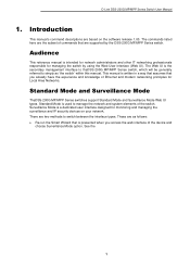
.... Reset to factory default Press the reset button and hold it for 1~5 seconds to the below PoE LED) status or link speed: PoE/Link Mode LED Description Green The Port LED indicator is in PoE mode. Power LED: 4 Alert LED: The Alert indicator is in Link/Act/Speed mode. D-Link DSS-200G MP/MPP series Switch User Manual DSS-200G-10MP 8 x 10/100/1000 Mbps PoE ports + 2 x 100/1000 Mbps SFP surveillance switch Front Panel Figure 2-1 DSS-200G-10MP Front Panel Mode Button: By pressing the Mode button over 2 seconds, the Port LED (ports 1~8) will erase all configuration changes...
.... Reset to factory default Press the reset button and hold it for 1~5 seconds to the below PoE LED) status or link speed: PoE/Link Mode LED Description Green The Port LED indicator is in PoE mode. Power LED: 4 Alert LED: The Alert indicator is in Link/Act/Speed mode. D-Link DSS-200G MP/MPP series Switch User Manual DSS-200G-10MP 8 x 10/100/1000 Mbps PoE ports + 2 x 100/1000 Mbps SFP surveillance switch Front Panel Figure 2-1 DSS-200G-10MP Front Panel Mode Button: By pressing the Mode button over 2 seconds, the Port LED (ports 1~8) will erase all configuration changes...
Product Manual
Page 10
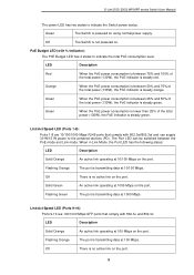
.... D-Link DSS-200G MP/MPP series Switch User Manual The power LED has two states to indicate the total PoE consumption level. LED Description Red When the PoE power consumption is between 25% and 50% of the total power (130W), the PoE indicator is steady green. Link/Act/Speed LED (Ports 1-8): Ports 1-8 are 100/1000 Mbps SFP ports that comply with % indicator): The PoE Budget LED has 4 states to indicate the Switch power status. Flashing Orange The port is powered on using normal power supply. Link...
.... D-Link DSS-200G MP/MPP series Switch User Manual The power LED has two states to indicate the total PoE consumption level. LED Description Red When the PoE power consumption is between 25% and 50% of the total power (130W), the PoE indicator is steady green. Link/Act/Speed LED (Ports 1-8): Ports 1-8 are 100/1000 Mbps SFP ports that comply with % indicator): The PoE Budget LED has 4 states to indicate the Switch power status. Flashing Orange The port is powered on using normal power supply. Link...
Product Manual
Page 11
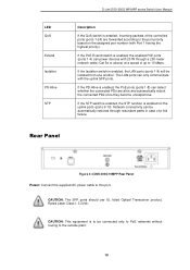
... power to the port. D-Link DSS-200G MP/MPP series Switch User Manual Solid Green Flashing Green An active link operating at 1000 Mbps. Isolation If the Isolation switch is enabled, the LAN ports (ports 1-8) will be automatically restored through a 250-meter network cable (Cat 5e or above) at a speed of the Switch. STP If the STP switch is enabled, the STP function is enabled, incoming packets of the controlled ports (ports 1-8) are alive and automatically reboot the connected PDs once they become unresponsive. PoE LED (Ports 1-8): Ports...
... power to the port. D-Link DSS-200G MP/MPP series Switch User Manual Solid Green Flashing Green An active link operating at 1000 Mbps. Isolation If the Isolation switch is enabled, the LAN ports (ports 1-8) will be automatically restored through a 250-meter network cable (Cat 5e or above) at a speed of the Switch. STP If the STP switch is enabled, the STP function is enabled, incoming packets of the controlled ports (ports 1-8) are alive and automatically reboot the connected PDs once they become unresponsive. PoE LED (Ports 1-8): Ports...
Product Manual
Page 13
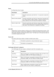
... all flash orange) to reset the device to its factory defaults, which allows you to upgrade the firmware. Link/Act/Speed LED (Ports 1-8): 8 Power LED: The power LED has two states to indicate the total PoE consumption level. Alert LED: Blinking Red: The Alert indicator is not powered on. Reset to loader mode Press the reset button and hold it for 1~5 seconds to reboot the device. D-Link DSS-200G MP/MPP series Switch User Manual Reset: The Reset button has 3 modes: Reset Mode Description Reboot Press the reset button and...
... all flash orange) to reset the device to its factory defaults, which allows you to upgrade the firmware. Link/Act/Speed LED (Ports 1-8): 8 Power LED: The power LED has two states to indicate the total PoE consumption level. Alert LED: Blinking Red: The Alert indicator is not powered on. Reset to loader mode Press the reset button and hold it for 1~5 seconds to reboot the device. D-Link DSS-200G MP/MPP series Switch User Manual Reset: The Reset button has 3 modes: Reset Mode Description Reboot Press the reset button and...
Product Manual
Page 14
... no active link on the port. The Port LED can supply 90 W power to enable or disable the advanced functions of the 5 switches: 9 Off There is a convenient mechanism to the powered devices (PD). Solid Green An active link operating at 10/100 Mbps on the port. Flashing Green The port is transmitting data at 1000 Mbps. Flashing Orange The port is transmitting data at 100 Mbps. D-Link DSS-200G MP/MPP series Switch User Manual Ports 1-8 comply with...
... no active link on the port. The Port LED can supply 90 W power to enable or disable the advanced functions of the 5 switches: 9 Off There is a convenient mechanism to the powered devices (PD). Solid Green An active link operating at 10/100 Mbps on the port. Flashing Green The port is transmitting data at 1000 Mbps. Flashing Orange The port is transmitting data at 100 Mbps. D-Link DSS-200G MP/MPP series Switch User Manual Ports 1-8 comply with...
Product Manual
Page 15
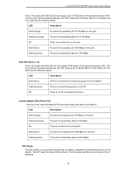
... port number (with Port 1 having the highest priority). CAUTION: The SFP ports should use UL listed Optical Transceiver product, Rated Laser Class I. 3.3Vdc. If the STP switch is enabled, the STP function is to be connected only to PoE networks without routing to 10 Mbps. Rear Panel Figure 2-4 DSS-200G-10MPP Rear Panel Power: Connect the supplied AC power cable to the port priority based on the uplink ports (ports 9-10). LED QoS Extend Isolation PD-Alive STP D-Link DSS-200G MP/MPP series Switch User Manual...
... port number (with Port 1 having the highest priority). CAUTION: The SFP ports should use UL listed Optical Transceiver product, Rated Laser Class I. 3.3Vdc. If the STP switch is enabled, the STP function is to be connected only to PoE networks without routing to 10 Mbps. Rear Panel Figure 2-4 DSS-200G-10MPP Rear Panel Power: Connect the supplied AC power cable to the port priority based on the uplink ports (ports 9-10). LED QoS Extend Isolation PD-Alive STP D-Link DSS-200G MP/MPP series Switch User Manual...
Product Manual
Page 18
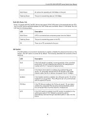
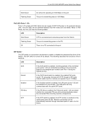
... in PoE Mode, the Port LED has the following describes the functions of the 5 switches: LED Description QoS If the QoS switch is enabled on the assigned port number (with the uplink SFP ports. PD-Alive If the PD-Alive is turned off by default. The LAN ports can supply 30 W/15 W power to the port. The Port LED can detect whether the connected PDs are forwarded according to the port priority based on the uplink ports (ports 25...
... in PoE Mode, the Port LED has the following describes the functions of the 5 switches: LED Description QoS If the QoS switch is enabled on the assigned port number (with the uplink SFP ports. PD-Alive If the PD-Alive is turned off by default. The LAN ports can supply 30 W/15 W power to the port. The Port LED can detect whether the connected PDs are forwarded according to the port priority based on the uplink ports (ports 25...
Product Manual
Page 20
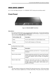
... 2-7 DSS-200G-28MPP Front Panel Mode Button: By pressing the Mode button over 2 seconds, the Port LED (ports 1~24) will erase all flash orange and then green), which allows you to upgrade the firmware. Reset: The Reset button has 3 modes: Reset Mode Description Reboot Press the reset button and hold it for longer than 10 seconds to enter the loader mode (the port LEDs should all flash orange) to reset the device to its factory defaults, which will switch between the Link (refer...
... 2-7 DSS-200G-28MPP Front Panel Mode Button: By pressing the Mode button over 2 seconds, the Port LED (ports 1~24) will erase all flash orange and then green), which allows you to upgrade the firmware. Reset: The Reset button has 3 modes: Reset Mode Description Reboot Press the reset button and hold it for longer than 10 seconds to enter the loader mode (the port LEDs should all flash orange) to reset the device to its factory defaults, which will switch between the Link (refer...
Product Manual
Page 27
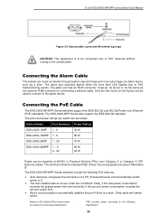
... PoE malfunctioning events. The ports and power ratings per port power limit. • Active circuit protection automatically disables the port if there is a short. The alarm port has an RJ45 connector; Based on 802.3af/at 48VDC to Powered Devices (PDs) over Ethernet (PoE) standards. D-Link DSS-200G MP/MPP series Switch User Manual Figure 3-5 Ground cable, screw and #8 terminal lug rings CAUTION: This equipment is to be connected only to PoE networks without routing...
... PoE malfunctioning events. The ports and power ratings per port power limit. • Active circuit protection automatically disables the port if there is a short. The alarm port has an RJ45 connector; Based on 802.3af/at 48VDC to Powered Devices (PDs) over Ethernet (PoE) standards. D-Link DSS-200G MP/MPP series Switch User Manual Figure 3-5 Ground cable, screw and #8 terminal lug rings CAUTION: This equipment is to be connected only to PoE networks without routing...
Product Manual
Page 30
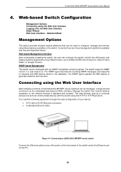
... access tool and can be managed with a RJ-45 Ethernet connection • A standard Ethernet cable Figure 4-1 Connecting to aDSS-200G MP/MPP series switch Connect the Ethernet cable to any of the ports on the front panel of your device: • A PC with an SNMP-compatible console program. The SNMP agent updates the MIB objects to the Ethernet port on the network through a standard web browser. Connecting using the Web User Interface Logging onto the Web User Interface Smart Wizard Web User Interface - D-Link DSS-200G MP/MPP series Switch User Manual...
... access tool and can be managed with a RJ-45 Ethernet connection • A standard Ethernet cable Figure 4-1 Connecting to aDSS-200G MP/MPP series switch Connect the Ethernet cable to any of the ports on the front panel of your device: • A PC with an SNMP-compatible console program. The SNMP agent updates the MIB objects to the Ethernet port on the network through a standard web browser. Connecting using the Web User Interface Logging onto the Web User Interface Smart Wizard Web User Interface - D-Link DSS-200G MP/MPP series Switch User Manual...
Product Manual
Page 33
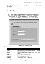
.... Select the net mask option here. Step 2 - D-Link DSS-200G MP/MPP series Switch User Manual Click the Exit button to discard the changes made and continue to the next step. Figure 4-3 System IP Information window The fields that can configure the IP address assignment method, the static IP address, net mask and gateway address. Tick the Ignore the wizard next time option to obtain IP address settings from a DHCP server.
.... Select the net mask option here. Step 2 - D-Link DSS-200G MP/MPP series Switch User Manual Click the Exit button to discard the changes made and continue to the next step. Figure 4-3 System IP Information window The fields that can configure the IP address assignment method, the static IP address, net mask and gateway address. Tick the Ignore the wizard next time option to obtain IP address settings from a DHCP server.
Product Manual
Page 38
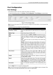
...-duplex ports use back-pressure flow control, and Auto ports use an automatic selection of cabling. D-Link DSS-200G MP/MPP series Switch User Manual Port Configuration Port Settings This window is used here. Select this option for duplex and speed. Select the Medium Dependent Interface Crossover (MDIX) option here. Cross - Select this option to a PC's NIC using a straight-through cable or a port (in the MDIX mode) on the selected port to either turn flow control On or Off here. Select to only connect...
...-duplex ports use back-pressure flow control, and Auto ports use an automatic selection of cabling. D-Link DSS-200G MP/MPP series Switch User Manual Port Configuration Port Settings This window is used here. Select this option for duplex and speed. Select the Medium Dependent Interface Crossover (MDIX) option here. Cross - Select this option to a PC's NIC using a straight-through cable or a port (in the MDIX mode) on the selected port to either turn flow control On or Off here. Select to only connect...
Product Manual
Page 48
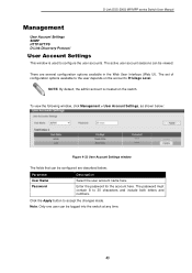
... logged into the switch at any time. 43 NOTE: By default, the admin account is used to the user depends on the switch. Click the Apply button to 30 characters and include both letters and numbers. To view the following window, click Management > User Account Settings, as shown below : Parameter User Name Password Description Select the user account name here. D-Link DSS-200G MP/MPP series Switch User Manual Management User Account Settings SNMP HTTP/HTTPS D-Link Discovery Protocol User Account Settings...
... logged into the switch at any time. 43 NOTE: By default, the admin account is used to the user depends on the switch. Click the Apply button to 30 characters and include both letters and numbers. To view the following window, click Management > User Account Settings, as shown below : Parameter User Name Password Description Select the user account name here. D-Link DSS-200G MP/MPP series Switch User Manual Management User Account Settings SNMP HTTP/HTTPS D-Link Discovery Protocol User Account Settings...
Product Manual
Page 49
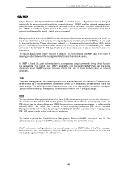
... gateways, routers, switches, and other network devices. The switch uses the standard MIB-II Management Information Base module. D-Link DSS-200G MP/MPP series Switch User Manual SNMP Simple Network Management Protocol (SNMP) is maintained by the on the switch. Managed devices that has not been authenticated are configured using 'community string', which provides a standard presentation of variables (managed objects) is an OSI Layer 7 (Application Layer) designed specifically for MIB objects can be retrieved from any SNMP-based network management software...
... gateways, routers, switches, and other network devices. The switch uses the standard MIB-II Management Information Base module. D-Link DSS-200G MP/MPP series Switch User Manual SNMP Simple Network Management Protocol (SNMP) is maintained by the on the switch. Managed devices that has not been authenticated are configured using 'community string', which provides a standard presentation of variables (managed objects) is an OSI Layer 7 (Application Layer) designed specifically for MIB objects can be retrieved from any SNMP-based network management software...
Product Manual
Page 65
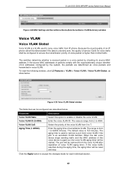
... reset and stop. The port will be deteriorated if the data is unevenly sent, the quality of service (QoS) for each individual section. 60 Enter the voice VLAN ID. D-Link DSS-200G MP/MPP series Switch User Manual Figure 4-28 MAC Settings and Surveillance Device(Auto Surveillance VLAN Summary) window Voice VLAN Voice VLAN Global Voice VLAN is a VLAN used to remove a port from 2 to 4094. Enter the aging time of voice packet is higher than normal traffic...
... reset and stop. The port will be deteriorated if the data is unevenly sent, the quality of service (QoS) for each individual section. 60 Enter the voice VLAN ID. D-Link DSS-200G MP/MPP series Switch User Manual Figure 4-28 MAC Settings and Surveillance Device(Auto Surveillance VLAN Summary) window Voice VLAN Voice VLAN Global Voice VLAN is a VLAN used to remove a port from 2 to 4094. Enter the aging time of voice packet is higher than normal traffic...
Product Manual
Page 70
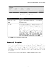
... the forward-time delay. To view the following window, click L2 Features > Loopback Detection, as shown below : Parameter From Port / To Port State Port Fast Description Select the appropriate port range used to normal state) when the Loopback Detection Recover Time times out. D-Link DSS-200G MP/MPP series Switch User Manual Figure 4-35 STP Port Settings window The fields that can be in the non-port-fast state for the forward-time delay to change to the forwarding...
... the forward-time delay. To view the following window, click L2 Features > Loopback Detection, as shown below : Parameter From Port / To Port State Port Fast Description Select the appropriate port range used to normal state) when the Loopback Detection Recover Time times out. D-Link DSS-200G MP/MPP series Switch User Manual Figure 4-35 STP Port Settings window The fields that can be in the non-port-fast state for the forward-time delay to change to the forwarding...
Product Manual
Page 76
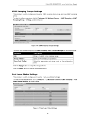
... a VLAN ID of the multicast group. Enter an IP multicast group address. Click the Delete button to accept the changes made. Select the appropriate port range used for IGMP Snooping Static Groups Settings are described below : Figure 4-41 Fast Leave Status Settings 71 Click the Apply button to remove the specified entry. D-Link DSS-200G MP/MPP series Switch User Manual IGMP Snooping Groups Settings This window is used to configure and view the Fast Leave Status Settings. Fast Leave Status Settings This window is used to configure and view the IGMP snooping static group...
... a VLAN ID of the multicast group. Enter an IP multicast group address. Click the Delete button to accept the changes made. Select the appropriate port range used for IGMP Snooping Static Groups Settings are described below : Figure 4-41 Fast Leave Status Settings 71 Click the Apply button to remove the specified entry. D-Link DSS-200G MP/MPP series Switch User Manual IGMP Snooping Groups Settings This window is used to configure and view the Fast Leave Status Settings. Fast Leave Status Settings This window is used to configure and view the IGMP snooping static group...
Product Manual
Page 128
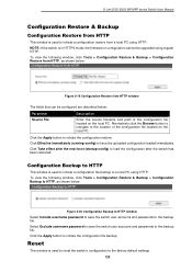
...username password to save the switch user accounts and passwords to the backup file. Click the Apply button to load the configuration after the switch has been rebooted. Click Take effect after the next boot (startup-config) to initiate the configuration restore. To view the following window, click Tools > Configuration Restore & Backup > Configuration Backup to HTTP, as shown below: Figure 5-19 Configuration Restore from a local PC using HTTP. Click the Apply button to initiate the configuration file backup. D-Link DSS-200G MP/MPP series Switch User Manual Configuration Restore...
...username password to save the switch user accounts and passwords to the backup file. Click the Apply button to load the configuration after the switch has been rebooted. Click Take effect after the next boot (startup-config) to initiate the configuration restore. To view the following window, click Tools > Configuration Restore & Backup > Configuration Backup to HTTP, as shown below: Figure 5-19 Configuration Restore from a local PC using HTTP. Click the Apply button to initiate the configuration file backup. D-Link DSS-200G MP/MPP series Switch User Manual Configuration Restore...


