Light Fix
Page 5
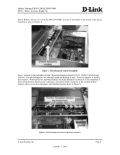
...most headers are made difficult to see the bare backplane and identified headers shown in figure 5) Figure 4: Identifying the four 10-position headers D-Link Systems, Inc. Figure 3: Identifying the chassis backplane Step 6) Located on the backplane are extremely small and difficult to ... connectors. (In order to better orient you to read. xStack Storage DSN-3200 & DSN-3400 ECN - Located in figure 3. February 7, 2008 Page 5 The labels themselves are four 10-position headers labeled NA1315, NA0912, NA0508 and NA0104. Drive Activity Light Fix Step 5) Remove the top cover from the...
...most headers are made difficult to see the bare backplane and identified headers shown in figure 5) Figure 4: Identifying the four 10-position headers D-Link Systems, Inc. Figure 3: Identifying the chassis backplane Step 6) Located on the backplane are extremely small and difficult to ... connectors. (In order to better orient you to read. xStack Storage DSN-3200 & DSN-3400 ECN - Located in figure 3. February 7, 2008 Page 5 The labels themselves are four 10-position headers labeled NA1315, NA0912, NA0508 and NA0104. Drive Activity Light Fix Step 5) Remove the top cover from the...

Light Fix
Page 6
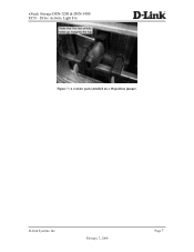
... your unit's cover and return to Section 2 for instructions on installing the new resistor packs. If you will need to proceed to normal operation. Drive Activity Light Fix Figure 5: A bare chassis backplane showing the four 10-position headers Step 7) If you see a jumper block installed on a 10-position jumper D-Link Systems, Inc. xStack Storage DSN-3200 & DSN-3400 ECN -
... your unit's cover and return to Section 2 for instructions on installing the new resistor packs. If you will need to proceed to normal operation. Drive Activity Light Fix Figure 5: A bare chassis backplane showing the four 10-position headers Step 7) If you see a jumper block installed on a 10-position jumper D-Link Systems, Inc. xStack Storage DSN-3200 & DSN-3400 ECN -
Light Fix
Page 7
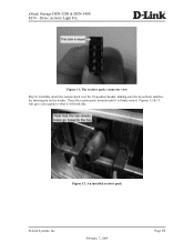
xStack Storage DSN-3200 & DSN-3400 ECN - Drive Activity Light Fix Figure 7: A resistor pack installed on a 10-position jumper. D-Link Systems, Inc. February 7, 2008 Page 7
xStack Storage DSN-3200 & DSN-3400 ECN - Drive Activity Light Fix Figure 7: A resistor pack installed on a 10-position jumper. D-Link Systems, Inc. February 7, 2008 Page 7

Light Fix
Page 8
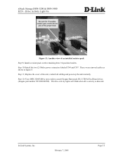
...CN7 Molex power connectors D-Link Systems, Inc. February 7, 2008 Page 8 Step 4) Identify the four 10-position headers as shown in figure 3. The two right-most headers are blocked by the power connectors. Step 1) Shut down the DSN-3200/3400 through your xStack Storage User's Guide. These ...resistor packs will take the place of each of the four jumpers found below them. Remove the two (2) Molex power connectors labeled CN4 and CN7 to gain easier access to obtain the four (4) necessary resistor packs. Drive...
...CN7 Molex power connectors D-Link Systems, Inc. February 7, 2008 Page 8 Step 4) Identify the four 10-position headers as shown in figure 3. The two right-most headers are blocked by the power connectors. Step 1) Shut down the DSN-3200/3400 through your xStack Storage User's Guide. These ...resistor packs will take the place of each of the four jumpers found below them. Remove the two (2) Molex power connectors labeled CN4 and CN7 to gain easier access to obtain the four (4) necessary resistor packs. Drive...

Light Fix
Page 9
...will need to match with the resistor pack. February 7, 2008 Page 9 xStack Storage DSN-3200 & DSN-3400 ECN - You will then see an empty 10-position header like that two of the positions are empty as seen in figure 10. This blocked hole will provide a guide for installation of the holes ... figure 11. Note that shown in figure 6. Also be aware that one of the new resistor pack. Figure 10: The resistor pack: side view D-Link Systems, Inc. Drive Activity Light Fix Step 6) For each 10-position header, you must remove the 4-position jumper block as shown in figure 9.
...will need to match with the resistor pack. February 7, 2008 Page 9 xStack Storage DSN-3200 & DSN-3400 ECN - You will then see an empty 10-position header like that two of the positions are empty as seen in figure 10. This blocked hole will provide a guide for installation of the holes ... figure 11. Note that shown in figure 6. Also be aware that one of the new resistor pack. Figure 10: The resistor pack: side view D-Link Systems, Inc. Drive Activity Light Fix Step 6) For each 10-position header, you must remove the 4-position jumper block as shown in figure 9.
Light Fix
Page 10
Drive Activity Light Fix Figure 11: The resistor pack: connector view Step 8) Carefully orient the resistor pack over the 10-position header, making sure the keyed hole matches the missing pin on the header. xStack Storage DSN-3200 & DSN-3400 ECN - Figures 12 & 13 will give you a guide to what it is firmly seated. February 7, 2008 Page 10 Press the resistor pack inwards until it will look like. Figure 12: An installed resistor pack D-Link Systems, Inc.
Drive Activity Light Fix Figure 11: The resistor pack: connector view Step 8) Carefully orient the resistor pack over the 10-position header, making sure the keyed hole matches the missing pin on the header. xStack Storage DSN-3200 & DSN-3400 ECN - Figures 12 & 13 will give you a guide to what it is firmly seated. February 7, 2008 Page 10 Press the resistor pack inwards until it will look like. Figure 12: An installed resistor pack D-Link Systems, Inc.
Light Fix
Page 11
xStack Storage DSN-3200 & DSN-3400 ECN - Step 12) Your DSN-3200/3400 is detected. D-Link Systems, Inc. The drive activity lights will blink when drive activity is now ready to accept Seagate Barracuda ES.2 1TB SATA-II hard drives (Seagate part number ST31000340NS). February 7, 2008 Page 11 Step 10) Install the two (2) Molex power connectors labeled CN4 and CN7. Step 11) Replace the...
xStack Storage DSN-3200 & DSN-3400 ECN - Step 12) Your DSN-3200/3400 is detected. D-Link Systems, Inc. The drive activity lights will blink when drive activity is now ready to accept Seagate Barracuda ES.2 1TB SATA-II hard drives (Seagate part number ST31000340NS). February 7, 2008 Page 11 Step 10) Install the two (2) Molex power connectors labeled CN4 and CN7. Step 11) Replace the...