
Hardware Installation Guide
Page 3
...DGS-3420 Series Layer 2+ Managed Stackable Gigabit Switch Hardware Installation Reference Guide Table of Contents Intended Readers ...v Typographical Conventions ...v Notes, Notices, and Cautions ...v Safety Instructions ...vi Safety Cautions...vi General Precautions for Rack-Mountable Products vii Protecting Against Electrostatic Discharge...viii Chapter 1 Introduction...9 Switch......34 SNMP Settings ...36 Traps ...36 Management Information Base (MIB) ...37 Chapter 5 Web-based Switch Configuration ...38 Introduction ...38 Logging onto the Web Manager ...38 Web-based User Interface...39 Areas ...
...DGS-3420 Series Layer 2+ Managed Stackable Gigabit Switch Hardware Installation Reference Guide Table of Contents Intended Readers ...v Typographical Conventions ...v Notes, Notices, and Cautions ...v Safety Instructions ...vi Safety Cautions...vi General Precautions for Rack-Mountable Products vii Protecting Against Electrostatic Discharge...viii Chapter 1 Introduction...9 Switch......34 SNMP Settings ...36 Traps ...36 Management Information Base (MIB) ...37 Chapter 5 Web-based Switch Configuration ...38 Introduction ...38 Logging onto the Web Manager ...38 Web-based User Interface...39 Areas ...

Hardware Installation Guide
Page 4
xStack® DGS-3420 Series Layer 2+ Managed Stackable Gigabit Switch Hardware Installation Reference Guide Appendix Section ...41 Appendix A - Module Specs and Cable Lengths...51 Warranties...52 Technical Support ...53 iv Cables and Connectors ...47 Ethernet Cable ...47 Console Cable ...48 Redundant Power Supply (RPS) Cable ...49 Appendix C - Technical Specifications ...41 General ...41 Physical and Environmental...41 Performance...42 LED Indicators ...43 Port Functions ...44 Appendix B -
xStack® DGS-3420 Series Layer 2+ Managed Stackable Gigabit Switch Hardware Installation Reference Guide Appendix Section ...41 Appendix A - Module Specs and Cable Lengths...51 Warranties...52 Technical Support ...53 iv Cables and Connectors ...47 Ethernet Cable ...47 Console Cable ...48 Redundant Power Supply (RPS) Cable ...49 Appendix C - Technical Specifications ...41 General ...41 Physical and Environmental...41 Performance...42 LED Indicators ...43 Port Functions ...44 Appendix B -
Hardware Installation Guide
Page 5
...means the Port Properties menu option under the Device menu. For example: Open the File menu and choose Cancel. For example: use the DGS-3420-28PC Switch. A CAUTION indicates a potential for emphasis. For example: Click Enter. Indicates a window name or a field. Notes, Notices, and ...the Power over Ethernet examples, we'll use the copy command. v For all practical reasons the DGS-3420-28SC, DGS-3420-28TC, DGS-3420-26SC, DGS-3420-28PC, DGS-3420-52T, and the DGS-3420-52P will be typed instead of the device. Bold font is intended for network managers familiar with an...
...means the Port Properties menu option under the Device menu. For example: Open the File menu and choose Cancel. For example: use the DGS-3420-28PC Switch. A CAUTION indicates a potential for emphasis. For example: Click Enter. Indicates a window name or a field. Notes, Notices, and ...the Power over Ethernet examples, we'll use the copy command. v For all practical reasons the DGS-3420-28SC, DGS-3420-28TC, DGS-3420-26SC, DGS-3420-28PC, DGS-3420-52T, and the DGS-3420-52P will be typed instead of the device. Bold font is intended for network managers familiar with an...

Hardware Installation Guide
Page 6
...plugs or remove the grounding prong from radiators and heat sources. o Only a trained service technician should be sure the voltage selection switch (if provided) on the electrical ratings label. o The product does not operate correctly when the operating instructions are equipped with a...such as explained in your country. o Do not service any objects into the product. xStack® DGS-3420 Series Layer 2+ Managed Stackable Gigabit Switch Hardware Installation Reference Guide Safety Instructions Use the following precautions: • Observe and follow service markings.
...plugs or remove the grounding prong from radiators and heat sources. o Only a trained service technician should be sure the voltage selection switch (if provided) on the electrical ratings label. o The product does not operate correctly when the operating instructions are equipped with a...such as explained in your country. o Do not service any objects into the product. xStack® DGS-3420 Series Layer 2+ Managed Stackable Gigabit Switch Hardware Installation Reference Guide Safety Instructions Use the following precautions: • Observe and follow service markings.

Hardware Installation Guide
Page 7
... total rack load should not exceed 80 percent of the branch circuit rating. • Ensure that provides power to tip over . xStack® DGS-3420 Series Layer 2+ Managed Stackable Gigabit Switch Hardware Installation Reference Guide • To help protect the system from the power supplies. • Move products with care; Also, refer to...
... total rack load should not exceed 80 percent of the branch circuit rating. • Ensure that provides power to tip over . xStack® DGS-3420 Series Layer 2+ Managed Stackable Gigabit Switch Hardware Installation Reference Guide • To help protect the system from the power supplies. • Move products with care; Also, refer to...

Hardware Installation Guide
Page 8
... body. 2. To prevent static damage, discharge static electricity from the antistatic packing material until ready to discharge static electricity from electrostatic discharge (ESD): 1. xStack® DGS-3420 Series Layer 2+ Managed Stackable Gigabit Switch Hardware Installation Reference Guide Protecting Against Electrostatic Discharge Static electricity can harm delicate components inside the system. viii
... body. 2. To prevent static damage, discharge static electricity from the antistatic packing material until ready to discharge static electricity from electrostatic discharge (ESD): 1. xStack® DGS-3420 Series Layer 2+ Managed Stackable Gigabit Switch Hardware Installation Reference Guide Protecting Against Electrostatic Discharge Static electricity can harm delicate components inside the system. viii
Hardware Installation Guide
Page 9
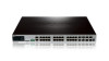
... Indicators Rear Panel Components Side Panel Components Switch Description D-Link's DGS-3420 Series is a high performance member of switches: • DGS-3420-28SC: 20 SFP ports + 4 Combo 1000Base-T/SFP ports + 4 10GE SFP+ ports L2+ Stackable Managed Switch • DGS-3420-28TC: 20 10/100/1000Base-T ports ...L2+ Stackable Managed Switch • DGS-3420-28PC: 20 10/100/1000Base-T PoE ports + 4 Combo 1000Base-T PoE/SFP ports + 4 10GE SFP+ ports L2+ Stackable Managed Switch • DGS-3420-52T: 48 10/100/1000Base-T ports + 4 10GE SFP+ ports L2+ Stackable Managed Switch • DGS-3420-52P: 48 ...
... Indicators Rear Panel Components Side Panel Components Switch Description D-Link's DGS-3420 Series is a high performance member of switches: • DGS-3420-28SC: 20 SFP ports + 4 Combo 1000Base-T/SFP ports + 4 10GE SFP+ ports L2+ Stackable Managed Switch • DGS-3420-28TC: 20 10/100/1000Base-T ports ...L2+ Stackable Managed Switch • DGS-3420-28PC: 20 10/100/1000Base-T PoE ports + 4 Combo 1000Base-T PoE/SFP ports + 4 10GE SFP+ ports L2+ Stackable Managed Switch • DGS-3420-52T: 48 10/100/1000Base-T ports + 4 10GE SFP+ ports L2+ Stackable Managed Switch • DGS-3420-52P: 48 ...

Hardware Installation Guide
Page 10
... DGS-3420 Series Layer 2+ Managed Stackable Gigabit Switch Hardware Installation Reference Guide Features The list of features below highlights the significant features of up to 64 MAC addresses per port. • Supports Broadcast, Multicast, and Unicast Control. • Supports Traffic Segmentation • Supports D-Link...STP/RSTP and 802.1Q 2005 MSTP. • Supports Loopback Detection (LBD). • Supports Link Aggregation (802.3ad and 802.3AX) with a maximum of 32 groups per Switch. • Supports Mirroring with RSPAN. • Supports Layer 2 Protocol Tunneling (L2PT) with ...
... DGS-3420 Series Layer 2+ Managed Stackable Gigabit Switch Hardware Installation Reference Guide Features The list of features below highlights the significant features of up to 64 MAC addresses per port. • Supports Broadcast, Multicast, and Unicast Control. • Supports Traffic Segmentation • Supports D-Link...STP/RSTP and 802.1Q 2005 MSTP. • Supports Loopback Detection (LBD). • Supports Link Aggregation (802.3ad and 802.3AX) with a maximum of 32 groups per Switch. • Supports Mirroring with RSPAN. • Supports Layer 2 Protocol Tunneling (L2PT) with ...

Hardware Installation Guide
Page 11
... DGS-3420-28PC Twenty 10/100/1000BASE-T PoE ports. 11 This features includes Local and RADIUS databasis, Port-based Access Control, and MAC-based Access Control (MAC). • Supports Web-based Access Control (WAC) that are present within each switch. Four 10GE SFP+ ports DGS-3420... Network Access Protection (NAP) using 802.1X guest VLAN. • Supports Guest VLAN. • Supports 4 Level User Account Priledges called Link Status Mode and Cable Length Mode. • Support Time-based Power-over-Ethernet (PoE). • Supports Access Authentication Control utilizing TACACS, ...
... DGS-3420-28PC Twenty 10/100/1000BASE-T PoE ports. 11 This features includes Local and RADIUS databasis, Port-based Access Control, and MAC-based Access Control (MAC). • Supports Web-based Access Control (WAC) that are present within each switch. Four 10GE SFP+ ports DGS-3420... Network Access Protection (NAP) using 802.1X guest VLAN. • Supports Guest VLAN. • Supports 4 Level User Account Priledges called Link Status Mode and Cable Length Mode. • Support Time-based Power-over-Ethernet (PoE). • Supports Access Authentication Control utilizing TACACS, ...

Hardware Installation Guide
Page 12
xStack® DGS-3420 Series Layer 2+ Managed Stackable Gigabit Switch Hardware Installation Reference Guide DGS-3420-52T DGS-3420-52P Four 10/100/1000BASE-T/SFP Combo Copper/SFP ports. NOTE: For customers interested in D-View, D-Link Corporation's proprietary SNMP management software, go to a PC) • All the switches are equipt with one Redundant Power Supply (RPS) outlet for optional external...
xStack® DGS-3420 Series Layer 2+ Managed Stackable Gigabit Switch Hardware Installation Reference Guide DGS-3420-52T DGS-3420-52P Four 10/100/1000BASE-T/SFP Combo Copper/SFP ports. NOTE: For customers interested in D-View, D-Link Corporation's proprietary SNMP management software, go to a PC) • All the switches are equipt with one Redundant Power Supply (RPS) outlet for optional external...
Hardware Installation Guide
Page 13
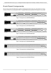
Figure 1-1 Front panel view of a DGS-3420-28SCSwitch Figure 1-2 Front panel view of a DGS-3420-28TC Switch Figure 1-3 Front panel view of a DGS-3420-26SC Switch Figure 1-4 Front panel view of a DGS-3420-28PC Switch Figure 1-5 Front panel view of a DGS-3420-52T Switch Figure 1-6 Front panel view of a Management and Console port, LED indicators for Power, Console, an Alarm Port, and stacking ID LED's. A separate...
Figure 1-1 Front panel view of a DGS-3420-28SCSwitch Figure 1-2 Front panel view of a DGS-3420-28TC Switch Figure 1-3 Front panel view of a DGS-3420-26SC Switch Figure 1-4 Front panel view of a DGS-3420-28PC Switch Figure 1-5 Front panel view of a DGS-3420-52T Switch Figure 1-6 Front panel view of a Management and Console port, LED indicators for Power, Console, an Alarm Port, and stacking ID LED's. A separate...
Hardware Installation Guide
Page 14
... for the DGS-3420-28PC Figure 1- 5. LED indicators for all ports including the Gigabit Ethernet ports. Figure 1- 1. xStack® DGS-3420 Series Layer 2+ Managed Stackable Gigabit Switch Hardware Installation Reference Guide LED Indicators The Switch front panel presents LED indicators for Power, Console, RPS, Master (stack control), SD, Stack ID and Link/Act indicators for the DGS-3420-28TC Figure...
... for the DGS-3420-28PC Figure 1- 5. LED indicators for all ports including the Gigabit Ethernet ports. Figure 1- 1. xStack® DGS-3420 Series Layer 2+ Managed Stackable Gigabit Switch Hardware Installation Reference Guide LED Indicators The Switch front panel presents LED indicators for Power, Console, RPS, Master (stack control), SD, Stack ID and Link/Act indicators for the DGS-3420-28TC Figure...
Hardware Installation Guide
Page 15
...is finished, the LED goes dark. The Switch has LED indicators for the DGS-3420-52P Description This LED will display number "1". When the POST is no longer receiving power (i.e. Only the DGS-3420-28PC and the DGS-3420-52P switches are equipt with a solid orange light, ...it means that the corresponding ports are not supplying power to be blinking. xStack® DGS-3420 Series Layer 2+ Managed Stackable Gigabit Switch Hardware Installation Reference Guide LED Power Console RPS SD Stack ID Link/...
...is finished, the LED goes dark. The Switch has LED indicators for the DGS-3420-52P Description This LED will display number "1". When the POST is no longer receiving power (i.e. Only the DGS-3420-28PC and the DGS-3420-52P switches are equipt with a solid orange light, ...it means that the corresponding ports are not supplying power to be blinking. xStack® DGS-3420 Series Layer 2+ Managed Stackable Gigabit Switch Hardware Installation Reference Guide LED Power Console RPS SD Stack ID Link/...

Hardware Installation Guide
Page 16
... three-pronged connector that supports the power cord. Figure 3-1 Rear panel view of a DGS-3420-28SC Switch Figure 3-2 Rear panel view of a DGS-3420-28TC Switch Figure 3-3 Rear panel view of a DGS-3420-26SC Switch Figure 3-4 Rear panel view of a DGS-3420-28PC Switch Figure 3-5 Rear panel view of a DGS-3420-52T Switch Figure 3-6 Rear panel view of the cord into a power outlet. Plug-in the...
... three-pronged connector that supports the power cord. Figure 3-1 Rear panel view of a DGS-3420-28SC Switch Figure 3-2 Rear panel view of a DGS-3420-28TC Switch Figure 3-3 Rear panel view of a DGS-3420-26SC Switch Figure 3-4 Rear panel view of a DGS-3420-28PC Switch Figure 3-5 Rear panel view of a DGS-3420-52T Switch Figure 3-6 Rear panel view of the cord into a power outlet. Plug-in the...
Hardware Installation Guide
Page 17
Figure 4-1 Side panels of the DGS-3420-28SC Switch Figure 4-1 Side panels of the DGS-3420-28TC Switch Figure 4-1 Side panels of the DGS-3420-26SC Switch Figure 4-1 Side panels of the Switch for proper ventilation. xStack® DGS-3420 Series Layer 2+ Managed Stackable Gigabit Switch Hardware Installation Reference Guide Side Panel Components The system heat vents located on each side dissipate heat. Do... overheat, which could lead to system failure or even severely damage components. Leave at least 6 inches of space at the rear and sides of the DGS-3420-28PC Switch 17
Figure 4-1 Side panels of the DGS-3420-28SC Switch Figure 4-1 Side panels of the DGS-3420-28TC Switch Figure 4-1 Side panels of the DGS-3420-26SC Switch Figure 4-1 Side panels of the Switch for proper ventilation. xStack® DGS-3420 Series Layer 2+ Managed Stackable Gigabit Switch Hardware Installation Reference Guide Side Panel Components The system heat vents located on each side dissipate heat. Do... overheat, which could lead to system failure or even severely damage components. Leave at least 6 inches of space at the rear and sides of the DGS-3420-28PC Switch 17

Hardware Installation Guide
Page 18
xStack® DGS-3420 Series Layer 2+ Managed Stackable Gigabit Switch Hardware Installation Reference Guide Figure 4-2 Side panels of the DGS-3420-52T Switch Figure 4-2 Side panels of the DGS-3420-52P Switch 18
xStack® DGS-3420 Series Layer 2+ Managed Stackable Gigabit Switch Hardware Installation Reference Guide Figure 4-2 Side panels of the DGS-3420-52T Switch Figure 4-2 Side panels of the DGS-3420-52P Switch 18

Hardware Installation Guide
Page 19
... Guide/D-View module If any item is missing or damaged, please contact your local D-Link Reseller for the acceptable temperature and humidity operating ranges. • Install the Switch in a site free from scratches and prevent it is fully secured to the AC power... sure that can support at the front and rear of the Switch for ventilation. • Install the Switch in a fairly cool and dry place for replacement. xStack® DGS-3420 Series Layer 2+ Managed Stackable Gigabit Switch Hardware Installation Reference Guide Chapter 2 Installation Package Contents Installation Guidelines Power...
... Guide/D-View module If any item is missing or damaged, please contact your local D-Link Reseller for the acceptable temperature and humidity operating ranges. • Install the Switch in a site free from scratches and prevent it is fully secured to the AC power... sure that can support at the front and rear of the Switch for ventilation. • Install the Switch in a fairly cool and dry place for replacement. xStack® DGS-3420 Series Layer 2+ Managed Stackable Gigabit Switch Hardware Installation Reference Guide Chapter 2 Installation Package Contents Installation Guidelines Power...

Hardware Installation Guide
Page 20
... and cooling. 20 With the brackets attached securely, the Switch can be mounted in a standard rack, as a guide. xStack® DGS-3420 Series Layer 2+ Managed Stackable Gigabit Switch Hardware Installation Reference Guide Installing the Switch without a Rack First, attach the rubber feet included with the Switch if installing on the bottom at each corner of the...
... and cooling. 20 With the brackets attached securely, the Switch can be mounted in a standard rack, as a guide. xStack® DGS-3420 Series Layer 2+ Managed Stackable Gigabit Switch Hardware Installation Reference Guide Installing the Switch without a Rack First, attach the rubber feet included with the Switch if installing on the bottom at each corner of the...

Hardware Installation Guide
Page 21
...the power socket. CAUTION: Installing systems in injury. xStack® DGS-3420 Series Layer 2+ Managed Stackable Gigabit Switch Hardware Installation Reference Guide Mounting the Switch in a Standard 19" Rack Figure 2-3 Mount the switch in the rack. Power Failure (AC Power) In the event of the Switch and the other end into the power connector of a power... failure, just as a precaution, unplug the Switch. The weight of more than one component out of the rack on , the LED's blink green to tip over , potentially resulting in to use ...
...the power socket. CAUTION: Installing systems in injury. xStack® DGS-3420 Series Layer 2+ Managed Stackable Gigabit Switch Hardware Installation Reference Guide Mounting the Switch in a Standard 19" Rack Figure 2-3 Mount the switch in the rack. Power Failure (AC Power) In the event of the Switch and the other end into the power connector of a power... failure, just as a precaution, unplug the Switch. The weight of more than one component out of the rack on , the LED's blink green to tip over , potentially resulting in to use ...

Hardware Installation Guide
Page 22
Connect the alarm output pins to alarm output terminals on other pieces of equipment. 22 xStack® DGS-3420 Series Layer 2+ Managed Stackable Gigabit Switch Hardware Installation Reference Guide Figure 2-1. Normal Open Pin. (42VAC or 60VDC) Input 2 Input 2 Input 1 Input 1 Connect the alarm input pins to alarm input terminals on other pieces of equipment. Normal Closed Pin. (42VAC or 60VDC) Output. Alarm Connector Contact 1 2 3 4 5 6 7 Alarm Connector Port Description Output. Common Pin. (42VAC or 60VDC) Output.
Connect the alarm output pins to alarm output terminals on other pieces of equipment. 22 xStack® DGS-3420 Series Layer 2+ Managed Stackable Gigabit Switch Hardware Installation Reference Guide Figure 2-1. Normal Open Pin. (42VAC or 60VDC) Input 2 Input 2 Input 1 Input 1 Connect the alarm input pins to alarm input terminals on other pieces of equipment. Normal Closed Pin. (42VAC or 60VDC) Output. Alarm Connector Contact 1 2 3 4 5 6 7 Alarm Connector Port Description Output. Common Pin. (42VAC or 60VDC) Output.


