
Quick Install Guide
Page 7
... Power) ...33 Installing Power Cord Retainer ...33 vii Hardware Components ...12 DGS-3130-30TS Switch...12 Front Panel Components...12 LED Indicators ...12 Rear Panel Components ...14 Side Panel Components ...14 DGS-3130-30S Switch ...15 Front Panel Components...15 LED Indicators ...15 Rear Panel Components... ...17 Side Panel Components ...17 DGS-3130-30PS Switch ...18 Front Panel Components...18 LED Indicators ...18 Rear ...
... Power) ...33 Installing Power Cord Retainer ...33 vii Hardware Components ...12 DGS-3130-30TS Switch...12 Front Panel Components...12 LED Indicators ...12 Rear Panel Components ...14 Side Panel Components ...14 DGS-3130-30S Switch ...15 Front Panel Components...15 LED Indicators ...15 Rear Panel Components... ...17 Side Panel Components ...17 DGS-3130-30PS Switch ...18 Front Panel Components...18 LED Indicators ...18 Rear ...
Quick Install Guide
Page 9
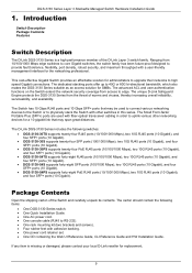
... One rack mounting kit (two brackets and screws). • Four rubber feet with other networking devices for replacement. 9 The D-Link DGS-3130 Series includes the following items: • One DGS-3130 Series switch. • One Quick Installation Guide. • One AC power cord. • One console cable (RJ45 to ...ports (10 Gigabit), and four SFP+ ports (10 Gigabit). • DGS-3130-30S supports twenty-four SFP ports (100/1000 Mbps), two 10G RJ45 ports (10 Gigabit), and four SFP+ ports (10 Gigabit). • DGS-3130-30PS supports twenty-four PoE RJ45 ports (10/100/1000 Mbps), two 10G...
... One rack mounting kit (two brackets and screws). • Four rubber feet with other networking devices for replacement. 9 The D-Link DGS-3130 Series includes the following items: • One DGS-3130 Series switch. • One Quick Installation Guide. • One AC power cord. • One console cable (RJ45 to ...ports (10 Gigabit), and four SFP+ ports (10 Gigabit). • DGS-3130-30S supports twenty-four SFP ports (100/1000 Mbps), two 10G RJ45 ports (10 Gigabit), and four SFP+ ports (10 Gigabit). • DGS-3130-30PS supports twenty-four PoE RJ45 ports (10/100/1000 Mbps), two 10G...
Quick Install Guide
Page 12
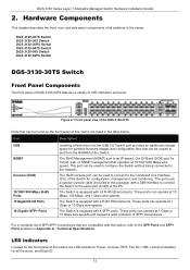
...(CLI) of this switch are listed in the series. DGS-3130-30TS Switch DGS-3130-30S Switch DGS-3130-30PS Switch DGS-3130-54TS Switch DGS-3130-54S Switch DGS-3130-54PS Switch DGS-3130-30TS Switch Front Panel Components The front panel of DGS-3130-30TS features a variety of all the ports, and Stack... at 10/100/1000 Mbps wirespeed. DGS-3130 Series Layer 3 Stackable Managed Switch Hardware Installation Guide 2. Figure 2-1 Front panel view of the DGS-3130-30TS Ports that are LED indicators: Power, Console, RPS, Fan Err, USB, Link/Act indicators for configuration, management, and...
...(CLI) of this switch are listed in the series. DGS-3130-30TS Switch DGS-3130-30S Switch DGS-3130-30PS Switch DGS-3130-54TS Switch DGS-3130-54S Switch DGS-3130-54PS Switch DGS-3130-30TS Switch Front Panel Components The front panel of DGS-3130-30TS features a variety of all the ports, and Stack... at 10/100/1000 Mbps wirespeed. DGS-3130 Series Layer 3 Stackable Managed Switch Hardware Installation Guide 2. Figure 2-1 Front panel view of the DGS-3130-30TS Ports that are LED indicators: Power, Console, RPS, Fan Err, USB, Link/Act indicators for configuration, management, and...

Quick Install Guide
Page 15
...the Switch. The RJ45 MGMT port is equipped with this switch are LED indicators: Power, Console, RPS, Fan Err, USB, Link/Act indicators for configuration, management, and monitoring. Port Description USB MGMT Console (RJ45) 100/1000 Mbps SFP Ports 10 Gigabit ...port can operate at 100 Mbps and 1 Gbps wire-speeds. DGS-3130 Series Layer 3 Stackable Managed Switch Hardware Installation Guide Figure 2-4 Side panels of the DGS-3130-30TS DGS-3130-30S Switch Front Panel Components The front panel of DGS-3130-30S features a variety of the Switch for all the ports, and ...
...the Switch. The RJ45 MGMT port is equipped with this switch are LED indicators: Power, Console, RPS, Fan Err, USB, Link/Act indicators for configuration, management, and monitoring. Port Description USB MGMT Console (RJ45) 100/1000 Mbps SFP Ports 10 Gigabit ...port can operate at 100 Mbps and 1 Gbps wire-speeds. DGS-3130 Series Layer 3 Stackable Managed Switch Hardware Installation Guide Figure 2-4 Side panels of the DGS-3130-30TS DGS-3130-30S Switch Front Panel Components The front panel of DGS-3130-30S features a variety of the Switch for all the ports, and ...

Quick Install Guide
Page 16
...the RJ45 console port is a connection (or link) to a 100 Mbps Ethernet device on any of the RJ45 ports. The Switch has LED indicators for the DGS-3130-30S Description This LED will light solid green when there is a connection (or link) to the MGMT port was successfully established. ...This LED will light solid green after a link to a 1000 Mbps Ethernet device or solid amber when...
...the RJ45 console port is a connection (or link) to a 100 Mbps Ethernet device on any of the RJ45 ports. The Switch has LED indicators for the DGS-3130-30S Description This LED will light solid green when there is a connection (or link) to the MGMT port was successfully established. ...This LED will light solid green after a link to a 1000 Mbps Ethernet device or solid amber when...

Quick Install Guide
Page 17
...security lock to 9 and the following letters H, h, E, and G. Figure 2-7 Rear Panel view of the DGS-3130-30S Components that can be off when there is active. LED Stack ID DGS-3130 Series Layer 3 Stackable Managed Switch Hardware Installation Guide Description when a 10 Gbps port is active or blink amber... when a 1 Gbps port is no link or activity. The stacking ID (1 to 9) can display numbers ...
...security lock to 9 and the following letters H, h, E, and G. Figure 2-7 Rear Panel view of the DGS-3130-30S Components that can be off when there is active. LED Stack ID DGS-3130 Series Layer 3 Stackable Managed Switch Hardware Installation Guide Description when a 10 Gbps port is active or blink amber... when a 1 Gbps port is no link or activity. The stacking ID (1 to 9) can display numbers ...
Quick Install Guide
Page 18
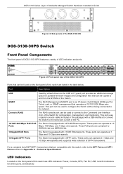
... IEEE802.3at. 10 Gigabit RJ45 Ports The Switch is equipped with this switch are LED indicators: Power, Console, RPS, Fan Err, USB, Link/Act indicators for Telnet, web, or SNMP management that operates at 10 Ports Mbps, 100 Mbps, and 1 Gbps wire-speeds. For a ... and SFP+ Ports sections in the table below. DGS-3130 Series Layer 3 Stackable Managed Switch Hardware Installation Guide Figure 2-8 Side panels of the DGS-3130-30S DGS-3130-30PS Switch Front Panel Components The front panel of DGS-3130-30PS features a variety of the DGS-3130-30PS Ports that can be used to configure the...
... IEEE802.3at. 10 Gigabit RJ45 Ports The Switch is equipped with this switch are LED indicators: Power, Console, RPS, Fan Err, USB, Link/Act indicators for Telnet, web, or SNMP management that operates at 10 Ports Mbps, 100 Mbps, and 1 Gbps wire-speeds. For a ... and SFP+ Ports sections in the table below. DGS-3130 Series Layer 3 Stackable Managed Switch Hardware Installation Guide Figure 2-8 Side panels of the DGS-3130-30S DGS-3130-30PS Switch Front Panel Components The front panel of DGS-3130-30PS features a variety of the DGS-3130-30PS Ports that can be used to configure the...

Quick Install Guide
Page 30
DGS-3130 Series Layer 3 Stackable Managed Switch Hardware Installation Guide Component Console (RJ45) Description speed. The heat vents are used to system failure or even severely damaged ... port uses a special console cable (included in this package) with a DB9 interface to connect the Switch to the Command Line Interface (CLI) of the DGS-3130-54PS 30 Side Panel Components The side panels of the PC. This port can be used to connect to the serial port (COM) of this switch contain...
DGS-3130 Series Layer 3 Stackable Managed Switch Hardware Installation Guide Component Console (RJ45) Description speed. The heat vents are used to system failure or even severely damaged ... port uses a special console cable (included in this package) with a DB9 interface to connect the Switch to the Command Line Interface (CLI) of the DGS-3130-54PS 30 Side Panel Components The side panels of the PC. This port can be used to connect to the serial port (COM) of this switch contain...
Quick Install Guide
Page 40
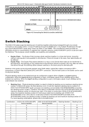
... a ring or circle format where data can be transferred in a chain-link format. If there is 9. Physical stacking needs to be enabled and can be configured to the table below. In DGS-3130 series, the total stacking cost is 12 and the maximum stacking device number... speed of up to 80Gbps will be used between switches in a stack is limited by multiple IP addresses through any of 9. Combination 1 2 3 4 5 6 7 DGS-3130-30TS/30S/30PS Device Number 9 8 7 6 5 4 3 DGS-3130-54TS/54S/54PS Device Number 0 1 2 3 3 4 4 Stacking Number 9 9 9 9 8 8 7 Stacking Cost 9 10 11 12 11 12 11 40...
... a ring or circle format where data can be transferred in a chain-link format. If there is 9. Physical stacking needs to be enabled and can be configured to the table below. In DGS-3130 series, the total stacking cost is 12 and the maximum stacking device number... speed of up to 80Gbps will be used between switches in a stack is limited by multiple IP addresses through any of 9. Combination 1 2 3 4 5 6 7 DGS-3130-30TS/30S/30PS Device Number 9 8 7 6 5 4 3 DGS-3130-54TS/54S/54PS Device Number 0 1 2 3 3 4 4 Stacking Number 9 9 9 9 8 8 7 Stacking Cost 9 10 11 12 11 12 11 40...

Quick Install Guide
Page 51
... cable, the boot procedure will be rebooted. Boot Procedure V1.00.001 Power On Self Test 100 % MAC Address : F0-7D-68-36-30-00 H/W Version : A1 Please Wait, Loading 1.00.001 Runtime Image UART init Starting runtime image Device Discovery Configuration init 100 % 100 % ...in the terminal. Figure 5-1 COM Port Configuration To be able to view the boot procedure, the Switch needs to be displayed. 51 DGS-3130 Series Layer 3 Stackable Managed Switch Hardware Installation Guide To configure the terminal emulation software as follows: • Select the appropriate serial port...
... cable, the boot procedure will be rebooted. Boot Procedure V1.00.001 Power On Self Test 100 % MAC Address : F0-7D-68-36-30-00 H/W Version : A1 Please Wait, Loading 1.00.001 Runtime Image UART init Starting runtime image Device Discovery Configuration init 100 % 100 % ...in the terminal. Figure 5-1 COM Port Configuration To be able to view the boot procedure, the Switch needs to be displayed. 51 DGS-3130 Series Layer 3 Stackable Managed Switch Hardware Installation Guide To configure the terminal emulation software as follows: • Select the appropriate serial port...
Quick Install Guide
Page 58
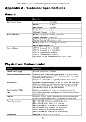
... and FAT32 file system architectures DGS-3130-30TS: 30.76W (Max.), 23.20W (Standby) DGS-3130-30S: 82.4W (Max.), 43.9W (Standby) DGS-3130-30PS: 471.67W (Max.), 52.44W (Standby) DGS-3130-54TS: 50.62W (Max.), 38.67W (Standby) DGS-3130-54S: 131W (Max.), 68.7W (Standby) DGS-3130-54PS: 487.26W (Max.),...;C (0 °F to secure the lock. This product is off The IC Sensor detects the temperature on the rear panel of 1 A. DGS-3130 Series Layer 3 Stackable Managed Switch Hardware Installation Guide Appendix A - The lock-andcable apparatus should be supplied by UL Listed Power source Provides ...
... and FAT32 file system architectures DGS-3130-30TS: 30.76W (Max.), 23.20W (Standby) DGS-3130-30S: 82.4W (Max.), 43.9W (Standby) DGS-3130-30PS: 471.67W (Max.), 52.44W (Standby) DGS-3130-54TS: 50.62W (Max.), 38.67W (Standby) DGS-3130-54S: 131W (Max.), 68.7W (Standby) DGS-3130-54PS: 487.26W (Max.),...;C (0 °F to secure the lock. This product is off The IC Sensor detects the temperature on the rear panel of 1 A. DGS-3130 Series Layer 3 Stackable Managed Switch Hardware Installation Guide Appendix A - The lock-andcable apparatus should be supplied by UL Listed Power source Provides ...
Quick Install Guide
Page 59
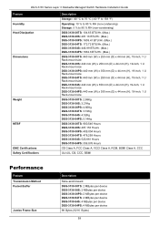
... mm (W) x 350 mm (D) x 44 mm (H), 19-inch, 1 U Rack-mount size DGS-3130-30TS: 2.98Kg DGS-3130-30S: 3.21Kg DGS-3130-30PS: 4.66Kg DGS-3130-54TS: 3.72Kg DGS-3130-54S: 4.52Kg DGS-3130-54PS: 5.14Kg DGS-3130-30TS: 900,546 Hours DGS-3130-30S: 487,153 Hours DGS-3130-30PS: 409,054 Hours DGS-3130-54TS: 478,258 Hours DGS-3130-54S: 520,861 Hours DGS-3130-54PS: 356,876 Hours CE Class A, FCC Class A, VCCI Class...
... mm (W) x 350 mm (D) x 44 mm (H), 19-inch, 1 U Rack-mount size DGS-3130-30TS: 2.98Kg DGS-3130-30S: 3.21Kg DGS-3130-30PS: 4.66Kg DGS-3130-54TS: 3.72Kg DGS-3130-54S: 4.52Kg DGS-3130-54PS: 5.14Kg DGS-3130-30TS: 900,546 Hours DGS-3130-30S: 487,153 Hours DGS-3130-30PS: 409,054 Hours DGS-3130-54TS: 478,258 Hours DGS-3130-54S: 520,861 Hours DGS-3130-54PS: 356,876 Hours CE Class A, FCC Class A, VCCI Class...
Quick Install Guide
Page 60
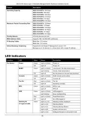
... DGS-3130-30S: 168 Gbps DGS-3130-30PS: 168 Gbps DGS-3130-54TS: 216 Gbps DGS-3130-54S: 216 Gbps DGS-3130-54PS: 216 Gbps DGS-3130-30TS: 125 Mpps DGS-3130-30S: 125 Mpps DGS-3130-30PS: 125 Mpps DGS-3130-54TS: 161 Mpps DGS-3130-54S: 161 Mpps DGS-3130-54PS: 161 Mpps 8 Priority Queues per port. Supports 16K (16,384) MAC addresses IPv4: Max. 512 entries IPv6: Max. 512 entries Supports D-Link...
... DGS-3130-30S: 168 Gbps DGS-3130-30PS: 168 Gbps DGS-3130-54TS: 216 Gbps DGS-3130-54S: 216 Gbps DGS-3130-54PS: 216 Gbps DGS-3130-30TS: 125 Mpps DGS-3130-30S: 125 Mpps DGS-3130-30PS: 125 Mpps DGS-3130-54TS: 161 Mpps DGS-3130-54S: 161 Mpps DGS-3130-54PS: 161 Mpps 8 Priority Queues per port. Supports 16K (16,384) MAC addresses IPv4: Max. 512 entries IPv6: Max. 512 entries Supports D-Link...

User Manual
Page 3
...2. Web-based Switch Configuration ...3 Management Options ...3 Logging into the Web UI ...3 Web User Interface (Web UI) ...4 Areas of Contents ...i 1. DGS-3130 Series Layer 3 Stackable Managed Switch Web UI Reference Guide Table of Contents Table of the User Interface...4 3. System ...6 Device Information ...6 System Information ... Encryption ...25 Password Recovery ...26 Login Method ...26 SNMP...28 SNMP Global Settings ...29 SNMP Linkchange Trap Settings ...30 SNMP View Table Settings ...31 SNMP Community Table Settings ...31 SNMP Group Table Settings ...32 SNMP Engine ID Local ...
...2. Web-based Switch Configuration ...3 Management Options ...3 Logging into the Web UI ...3 Web User Interface (Web UI) ...4 Areas of Contents ...i 1. DGS-3130 Series Layer 3 Stackable Managed Switch Web UI Reference Guide Table of Contents Table of the User Interface...4 3. System ...6 Device Information ...6 System Information ... Encryption ...25 Password Recovery ...26 Login Method ...26 SNMP...28 SNMP Global Settings ...29 SNMP Linkchange Trap Settings ...30 SNMP View Table Settings ...31 SNMP Community Table Settings ...31 SNMP Group Table Settings ...32 SNMP Engine ID Local ...

User Manual
Page 29
... The fields that will be configured are described below: Parameter Time Date Description Enter the current time in the table. For example, 30/04/2015. For example, 18:30:30. Enter the current day (DD), month (MM), and year (YYYY) here. To view the following window, click System > ...window is used to display and configure the time settings for SNTP. Click the Clear Attack Log button to accept the changes made. DGS-3130 Series Layer 3 Stackable Managed Switch Web UI Reference Guide Figure 3-14 System Attack Log Window The fields that can be configured are described...
... The fields that will be configured are described below: Parameter Time Date Description Enter the current time in the table. For example, 30/04/2015. For example, 18:30:30. Enter the current day (DD), month (MM), and year (YYYY) here. To view the following window, click System > ...window is used to display and configure the time settings for SNTP. Click the Clear Attack Log button to accept the changes made. DGS-3130 Series Layer 3 Stackable Managed Switch Web UI Reference Guide Figure 3-14 System Attack Log Window The fields that can be configured are described...

User Manual
Page 31
...that summer time will start . SNTP Settings The Simple Network Time Protocol (SNTP) is 30, 60, 90 and 120. To view the following window, click System > Time and...day that summer time will start . The range of this offset is 60. The default value is 30, 60, 90 and 120. Select the month that summer time will end. Enter the number of minutes...default value is used to display and configure the SNTP settings for synchronizing computer clocks through the Internet. DGS-3130 Series Layer 3 Stackable Managed Switch Web UI Reference Guide Parameter To: Week of the Month To: ...
...that summer time will start . SNTP Settings The Simple Network Time Protocol (SNTP) is 30, 60, 90 and 120. To view the following window, click System > Time and...day that summer time will start . The range of this offset is 60. The default value is 30, 60, 90 and 120. Select the month that summer time will end. Enter the number of minutes...default value is used to display and configure the SNTP settings for synchronizing computer clocks through the Internet. DGS-3130 Series Layer 3 Stackable Managed Switch Web UI Reference Guide Parameter To: Week of the Month To: ...

User Manual
Page 32
... seconds. Enter the IPv6 address of the SNTP server which provides the SNTP reference. This name can be used for this time profile from 30 to accept the changes made . The value is from the starting and ending days of the week that will be used for this time ... The first drop-down menu selects the hour and the second drop-down menu selects the minute. Click the Apply button to 32 characters long. DGS-3130 Series Layer 3 Stackable Managed Switch Web UI Reference Guide Parameter SNTP State Poll Interval Description Select this time profile for every day of the week...
... seconds. Enter the IPv6 address of the SNTP server which provides the SNTP reference. This name can be used for this time profile from 30 to accept the changes made . The value is from the starting and ending days of the week that will be used for this time ... The first drop-down menu selects the hour and the second drop-down menu selects the minute. Click the Apply button to 32 characters long. DGS-3130 Series Layer 3 Stackable Managed Switch Web UI Reference Guide Parameter SNTP State Poll Interval Description Select this time profile for every day of the week...

User Manual
Page 40
...is down notifications. Select this option to accept the changes made . The authentication method depends on the version of the communication links has come up notifications. A linkDown trap is generated when the device recognizes that are described below : Figure 4-8 SNMP ...the changes made . 30 Select this option to enable or disable the sending of SNMP authentication failure notifications. DGS-3130 Series Layer 3 Stackable Managed Switch Web UI Reference Guide Parameter Trap Global State SNMP Authentication Trap Port Link Up Port Link Down Coldstart Warmstart ...
...is down notifications. Select this option to accept the changes made . The authentication method depends on the version of the communication links has come up notifications. A linkDown trap is generated when the device recognizes that are described below : Figure 4-8 SNMP ...the changes made . 30 Select this option to enable or disable the sending of SNMP authentication failure notifications. DGS-3130 Series Layer 3 Stackable Managed Switch Web UI Reference Guide Parameter Trap Global State SNMP Authentication Trap Port Link Up Port Link Down Coldstart Warmstart ...

User Manual
Page 56
... hexadecimal string. Click the Apply button to accept the changes made . This string can be associated with this DHCP pool. DGS-3130 Series Layer 3 Stackable Managed Switch Web UI Reference Guide Figure 4-30 DHCP Server Pool Settings (Edit Class) Window The fields that can be configured are described below : Parameter Option Type Description...
... hexadecimal string. Click the Apply button to accept the changes made . This string can be associated with this DHCP pool. DGS-3130 Series Layer 3 Stackable Managed Switch Web UI Reference Guide Figure 4-30 DHCP Server Pool Settings (Edit Class) Window The fields that can be configured are described below : Parameter Option Type Description...

User Manual
Page 62
..., then the default valid lifetime will appear. If this value is not specified, then the default preferred lifetime will be 2592000 seconds (30 days). Select and enter the DHCPv6 server pool prefix delegation name here. The range is from 60 to a specific page when multiple ... The valid lifetime should be assigned to be greater than preferred lifetime. Enter the static binding IPv6 network address and prefix length here. DGS-3130 Series Layer 3 Stackable Managed Switch Web UI Reference Guide Enter a page number and click the Go button to navigate to 4294967295 seconds. ...
..., then the default valid lifetime will appear. If this value is not specified, then the default preferred lifetime will be 2592000 seconds (30 days). Select and enter the DHCPv6 server pool prefix delegation name here. The range is from 60 to a specific page when multiple ... The valid lifetime should be assigned to be greater than preferred lifetime. Enter the static binding IPv6 network address and prefix length here. DGS-3130 Series Layer 3 Stackable Managed Switch Web UI Reference Guide Enter a page number and click the Go button to navigate to 4294967295 seconds. ...