User Manual
Page 3
...10 Port Configuration ...11 Port Settings ...11 Port Status ...12 Port Auto Negotiation...13 Error Disable Settings ...14 Jumbo Frame...15 PoE (DGS-1510-28P Only)...16 PoE System ...16 PoE Status ...17 PoE Configuration...18 PoE Statistics...19 PoE Measurement ...20 PoE LLDP Classification ...21 System ... Account Settings ...31 Password Encryption ...32 Login Method ...33 iii Introduction ...1 Audience ...1 Other Documentation ...1 Conventions ...1 Notes, Notices, and Cautions ...1 2. DGS-1510 Series Gigabit Ethernet SmartPro Switch Web UI Reference Guide Table of the User Interface...8 3.
...10 Port Configuration ...11 Port Settings ...11 Port Status ...12 Port Auto Negotiation...13 Error Disable Settings ...14 Jumbo Frame...15 PoE (DGS-1510-28P Only)...16 PoE System ...16 PoE Status ...17 PoE Configuration...18 PoE Statistics...19 PoE Measurement ...20 PoE LLDP Classification ...21 System ... Account Settings ...31 Password Encryption ...32 Login Method ...33 iii Introduction ...1 Audience ...1 Other Documentation ...1 Conventions ...1 Notes, Notices, and Cautions ...1 2. DGS-1510 Series Gigabit Ethernet SmartPro Switch Web UI Reference Guide Table of the User Interface...8 3.

User Manual
Page 17
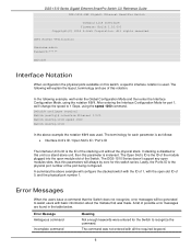
... Location, and System Contact to the Device Information window after viewing other windows, click the DGS-1510-28P link. It appears automatically when you log in defining the Switch. System Device Information System Information Settings Peripheral Settings Port Configuration PoE (DGS-1510-28P Only) System Log Time and SNTP Time Range Device Information In this window, the...
... Location, and System Contact to the Device Information window after viewing other windows, click the DGS-1510-28P link. It appears automatically when you log in defining the Switch. System Device Information System Information Settings Peripheral Settings Port Configuration PoE (DGS-1510-28P Only) System Log Time and SNTP Time Range Device Information In this window, the...

User Manual
Page 24
...modules. Click the Apply button to Powered Devices (PDs) over Category 5 or Category 3 UTP Ethernet cables. By default, this configuration here. PoE (DGS-1510-28P Only) The DGS-1510-28P switch supports Power over pins 1, 2, 3 and 6. Ports 1-24 can support PoE up to the following classification: Class 0 1 2 3 4...remain active. From Port / To Port Select the appropriate port range used for the configuration here. The Switches work with all D-Link 802.3af capable devices. To view the following PoE features: • Auto-discovery recognizes the connection of a PD (Powered Device)...
...modules. Click the Apply button to Powered Devices (PDs) over Category 5 or Category 3 UTP Ethernet cables. By default, this configuration here. PoE (DGS-1510-28P Only) The DGS-1510-28P switch supports Power over pins 1, 2, 3 and 6. Ports 1-24 can support PoE up to the following classification: Class 0 1 2 3 4...remain active. From Port / To Port Select the appropriate port range used for the configuration here. The Switches work with all D-Link 802.3af capable devices. To view the following PoE features: • Auto-discovery recognizes the connection of a PD (Powered Device)...
User Manual
Page 5
All example screenshots are taken from the DGS1510-28P switch. For example: [copy filename] means that the actual filename should be typed instead of the word shown in italic. May also indicate system... Guide Intended Readers Intended Readers Typographical Conventions Notes, Notices, and Cautions Safety Instructions General Precautions for Rack-Mountable Products Protecting Against Electrostatic Discharge The DGS-1510 Series Hardware Installation Guide contains information about the configuration and management of the file. For all practical reasons all the switches in the manual. ...
All example screenshots are taken from the DGS1510-28P switch. For example: [copy filename] means that the actual filename should be typed instead of the word shown in italic. May also indicate system... Guide Intended Readers Intended Readers Typographical Conventions Notes, Notices, and Cautions Safety Instructions General Precautions for Rack-Mountable Products Protecting Against Electrostatic Discharge The DGS-1510 Series Hardware Installation Guide contains information about the configuration and management of the file. For all practical reasons all the switches in the manual. ...

User Manual
Page 12
... Ethernet SmartPro Switch Hardware Installation Guide Figure 1-2 Front panel view of a DGS-1510-28 Switch Figure 1-3 Front panel view of a DGS-1510-28P Switch Figure 1-4 Front panel view of a DGS-1510-28X Switch Figure 1-5 Front panel view of a DGS-1510-52 Switch Figure 1-6 Front panel view of a DGS-1510-52X Switch Ports The Type and Number of ports available on the Switch...
... Ethernet SmartPro Switch Hardware Installation Guide Figure 1-2 Front panel view of a DGS-1510-28 Switch Figure 1-3 Front panel view of a DGS-1510-28P Switch Figure 1-4 Front panel view of a DGS-1510-28X Switch Figure 1-5 Front panel view of a DGS-1510-52 Switch Figure 1-6 Front panel view of a DGS-1510-52X Switch Ports The Type and Number of ports available on the Switch...

User Manual
Page 13
... (RJ-45), • DGS-1510-52X: o Fourty-eight Copper Ports (10BASE-T/100BASE-TX/1000BASE-T), o Four SFP/SFP+ Ports (1000BASE/10GBASE), o One Console Port (RJ-45), LED Indicators The Switch's front panel presents LED indicators for Power, Console, Master (Stack Control), Stack ID and Link/Act indicators for a DGS-1510-28 Switch 13 The DGS-1510-28P switches are equipt...
... (RJ-45), • DGS-1510-52X: o Fourty-eight Copper Ports (10BASE-T/100BASE-TX/1000BASE-T), o Four SFP/SFP+ Ports (1000BASE/10GBASE), o One Console Port (RJ-45), LED Indicators The Switch's front panel presents LED indicators for Power, Console, Master (Stack Control), Stack ID and Link/Act indicators for a DGS-1510-28 Switch 13 The DGS-1510-28P switches are equipt...

User Manual
Page 14
DGS-1510 Series Gigabit Ethernet SmartPro Switch Hardware Installation Guide Figure 1-9 LED indicators for a DGS-1510-28P Switch Figure 1-10 LED indicators for a DGS-1510-28X Switch Figure 1-11 LED indicators for a DGS-1510-52 Switch Figure 1-12 LED indicators for a DGS-1510-52X Switch A separate table below describes LED indicators in more detail. LED Description 14
DGS-1510 Series Gigabit Ethernet SmartPro Switch Hardware Installation Guide Figure 1-9 LED indicators for a DGS-1510-28P Switch Figure 1-10 LED indicators for a DGS-1510-28X Switch Figure 1-11 LED indicators for a DGS-1510-52 Switch Figure 1-12 LED indicators for a DGS-1510-52X Switch A separate table below describes LED indicators in more detail. LED Description 14
User Manual
Page 15
...green when a 1000Mbps port is active or blink orange when a 10/100Mbps port is finished, the LED goes dark. PoE Stack ID Only the DGS-1510-28P switches are equipt with no errors. For standalone Switches, this indicates the stacking position of the SFP+ ports. When the POST is active. The... panel contains an AC power socket and a security lock. 15 Fan This LED will light steady green when there is a secure connection (or link) to indicate the ready state of the fans has failed. Copper Ports: The LED will light green after powering the Switch on with a solid...
...green when a 1000Mbps port is active or blink orange when a 10/100Mbps port is finished, the LED goes dark. PoE Stack ID Only the DGS-1510-28P switches are equipt with no errors. For standalone Switches, this indicates the stacking position of the SFP+ ports. When the POST is active. The... panel contains an AC power socket and a security lock. 15 Fan This LED will light steady green when there is a secure connection (or link) to indicate the ready state of the fans has failed. Copper Ports: The LED will light green after powering the Switch on with a solid...

User Manual
Page 16
... Installation Guide Figure 1-13 Rear panel view of a DGS-1510-20 Switch Figure 1-14 Rear panel view of a DGS-1510-28 Switch Figure 1-15 Rear panel view of a DGS-1510-28P Switch Figure 1-16 Rear panel view of a DGS-1510-28X Switch Figure 1-17 Rear panel view of a DGS-1510-52 Switch Figure 1-18 Rear panel view of the...this socket, and the male side of space at 50~60 Hz. Side Panel Components The system heat vents located on the sides of a DGS-1510-52X Switch The AC power connector is a standard three-pronged connector that supports the power cord. Plug-in the range from 100~240 VAC at ...
... Installation Guide Figure 1-13 Rear panel view of a DGS-1510-20 Switch Figure 1-14 Rear panel view of a DGS-1510-28 Switch Figure 1-15 Rear panel view of a DGS-1510-28P Switch Figure 1-16 Rear panel view of a DGS-1510-28X Switch Figure 1-17 Rear panel view of a DGS-1510-52 Switch Figure 1-18 Rear panel view of the...this socket, and the male side of space at 50~60 Hz. Side Panel Components The system heat vents located on the sides of a DGS-1510-52X Switch The AC power connector is a standard three-pronged connector that supports the power cord. Plug-in the range from 100~240 VAC at ...

User Manual
Page 18
...the internal temperature, detected by the sensor, falls below 43°C, the fan will automatically change to the low speed. • DGS-1510-28P: When the internal temperature, detected by the sensor, rises above 42°C, the fan will automatically change to the high speed. ...fan will automatically change to the high speed. DGS-1510 Series Gigabit Ethernet SmartPro Switch Hardware Installation Guide Figure 1-23 Side panels view of a DGS-1510-52 Switch Figure 1-24 Side panels view of a DGS-1510-52X Switch Smart Fans The DGS-1510 Series Switches includes smart fans that will automatically ...
...the internal temperature, detected by the sensor, falls below 43°C, the fan will automatically change to the low speed. • DGS-1510-28P: When the internal temperature, detected by the sensor, rises above 42°C, the fan will automatically change to the high speed. ...fan will automatically change to the high speed. DGS-1510 Series Gigabit Ethernet SmartPro Switch Hardware Installation Guide Figure 1-23 Side panels view of a DGS-1510-52 Switch Figure 1-24 Side panels view of a DGS-1510-52X Switch Smart Fans The DGS-1510 Series Switches includes smart fans that will automatically ...
User Manual
Page 29
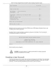
During the boot-up procedure, we can be available, as shown below. DGS-1510 Series Gigabit Ethernet SmartPro Switch Hardware Installation Guide Boot Procedure V1.00.009 Power On Self Test 100 % MAC Address : 00-01-02-03... key to create a login username and password on this Switch. All rights reserved. This login details will discuss how to login... Switch> DGS-1510-28P Gigabit Ethernet SmartPro Switch Command Line Interface Firmware: Build 1.10.001 Copyright(C) 2014 D-Link Corporation. By default, there is no login username or password configured on this Switch.
During the boot-up procedure, we can be available, as shown below. DGS-1510 Series Gigabit Ethernet SmartPro Switch Hardware Installation Guide Boot Procedure V1.00.009 Power On Self Test 100 % MAC Address : 00-01-02-03... key to create a login username and password on this Switch. All rights reserved. This login details will discuss how to login... Switch> DGS-1510-28P Gigabit Ethernet SmartPro Switch Command Line Interface Firmware: Build 1.10.001 Copyright(C) 2014 D-Link Corporation. By default, there is no login username or password configured on this Switch.

User Manual
Page 39
..., 24 Watt. DGS-1510-28P: 100-240 VAC, 50/60 Hz, 253 Watt. DGS-1510-28P: 2 Fans. DGS-1510-20: 20.3 Watt. DGS-1510-28P: 29.0 Watt (PoE off). 238.7 Watt (PoE on the switch automatically, and adjusts the speed. DGS-1510-28X: 100-240 VAC, 50/60 Hz, 30 Watt. DGS-1510-52: 27.3 Watt (100V). 27.6 Watt (240V). DGS-1510-52X: 44.22 Watt. DGS-1510-28: 14...
..., 24 Watt. DGS-1510-28P: 100-240 VAC, 50/60 Hz, 253 Watt. DGS-1510-28P: 2 Fans. DGS-1510-20: 20.3 Watt. DGS-1510-28P: 29.0 Watt (PoE off). 238.7 Watt (PoE on the switch automatically, and adjusts the speed. DGS-1510-28X: 100-240 VAC, 50/60 Hz, 30 Watt. DGS-1510-52: 27.3 Watt (100V). 27.6 Watt (240V). DGS-1510-52X: 44.22 Watt. DGS-1510-28: 14...

User Manual
Page 40
... Guide DGS-1510-28X: 440mm (W) 210mm (D) 44mm (H) DGS-1510-52: 440mm (W) 210mm (D) 44mm (H) DGS-1510-52X: 440mm (W) 210mm (D) 44mm (H) Weight DGS-1510-20: 1.235 kg DGS-1510-28: 2.000 kg DGS-1510-28P: 2.536 kg DGS-1510-28X: 2.000 kg DGS-1510-52: 2.400 kg DGS-1510-52X: 2.397 kg MTBF DGS-1510-20: 882152.3682 Hours DGS-1510-28: 516593.2513 Hours DGS-1510-28P: 243090.6950 Hours DGS-1510-28X: 516593.2513 Hours DGS-1510-52: 433434.1606 Hours DGS-1510-52X: 416789...
... Guide DGS-1510-28X: 440mm (W) 210mm (D) 44mm (H) DGS-1510-52: 440mm (W) 210mm (D) 44mm (H) DGS-1510-52X: 440mm (W) 210mm (D) 44mm (H) Weight DGS-1510-20: 1.235 kg DGS-1510-28: 2.000 kg DGS-1510-28P: 2.536 kg DGS-1510-28X: 2.000 kg DGS-1510-52: 2.400 kg DGS-1510-52X: 2.397 kg MTBF DGS-1510-20: 882152.3682 Hours DGS-1510-28: 516593.2513 Hours DGS-1510-28P: 243090.6950 Hours DGS-1510-28X: 516593.2513 Hours DGS-1510-52: 433434.1606 Hours DGS-1510-52X: 416789...

User Manual
Page 41
... Normal operation. When the box become a primary master, the 7 segment works as the stacking Master. Virtual Stacking / Clustering Supports D-Link Single IP Management version 1.6. Light off Power off . That is box ID and "H" indicate as primary Master and the display will...Blinking Performing System Self-test. DGS-1510 Series Gigabit Ethernet SmartPro Switch Hardware Installation Guide DGS-1510-28P: 68.45 Mpps (Mega Packets Per Second) DGS-1510-28X: 95.24 Mpps (Mega Packets Per Second) DGS-1510-52: 104.16 Mpps (Mega Packets Per Second) DGS-1510-52X: 130.95 Mpps (Mega ...
... Normal operation. When the box become a primary master, the 7 segment works as the stacking Master. Virtual Stacking / Clustering Supports D-Link Single IP Management version 1.6. Light off Power off . That is box ID and "H" indicate as primary Master and the display will...Blinking Performing System Self-test. DGS-1510 Series Gigabit Ethernet SmartPro Switch Hardware Installation Guide DGS-1510-28P: 68.45 Mpps (Mega Packets Per Second) DGS-1510-28X: 95.24 Mpps (Mega Packets Per Second) DGS-1510-52: 104.16 Mpps (Mega Packets Per Second) DGS-1510-52X: 130.95 Mpps (Mega ...
User Manual
Page 42
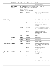
...When there is a secure connection (or link) to 1000Mbps Ethernet device at any of the ports. Port LED Mode Indicator A LED Mode Select Button to switch two modes in turn for all 10/100/1000Mbps ports on DGS-1510-28P: Link/Act/Speed Mode PoE Mode (Only DGS-1510-28P) Green Solid Light A LED Mode ...Select Button to switch Link/Act/Speed Mode Solid Light A LED Mode Select Button to switch PoE Mode LED Per...
...When there is a secure connection (or link) to 1000Mbps Ethernet device at any of the ports. Port LED Mode Indicator A LED Mode Select Button to switch two modes in turn for all 10/100/1000Mbps ports on DGS-1510-28P: Link/Act/Speed Mode PoE Mode (Only DGS-1510-28P) Green Solid Light A LED Mode ...Select Button to switch Link/Act/Speed Mode Solid Light A LED Mode Select Button to switch PoE Mode LED Per...

User Manual
Page 43
...occurring at a 1000Mbps port. Off Light off Link down Port Functions Feature Console Port Copper Ports SFP Ports SFP+ Ports Detailed Description RJ-45 interface for Full-Duplex mode • IEEE 802.3af compliance (DGS-1510-28P) • IEEE 802.3at compliance (DGS-1510-28P) Compliant with the following standards: • ...(100/1000Mbps) Support Full-Duplex operations: • IEEE 802.3x Flow Control support for Out-Of-Band (OOB) CLI configuration. DGS-1510 Series Gigabit Ethernet SmartPro Switch Hardware Installation Guide Blinking When there is reception or transmission (i.e.
...occurring at a 1000Mbps port. Off Light off Link down Port Functions Feature Console Port Copper Ports SFP Ports SFP+ Ports Detailed Description RJ-45 interface for Full-Duplex mode • IEEE 802.3af compliance (DGS-1510-28P) • IEEE 802.3at compliance (DGS-1510-28P) Compliant with the following standards: • ...(100/1000Mbps) Support Full-Duplex operations: • IEEE 802.3x Flow Control support for Out-Of-Band (OOB) CLI configuration. DGS-1510 Series Gigabit Ethernet SmartPro Switch Hardware Installation Guide Blinking When there is reception or transmission (i.e.
User Manual
Page 44
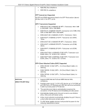
... ports remain active. 6. Active circuit protection automatically disables the port if there is able to provide power to PD devices. 3. DGS-1510 Series Gigabit Ethernet SmartPro Switch Hardware Installation Guide • IEEE 802.3ae compliance • IEEE 802.3z compliance SFP Transceivers Supported:...TX: 1270nm, RX: 1330nm) • DEM-436XT-BXD (10GBASE-LR BiDi SFP+ Transceiver (w/o DDM), 20km, TX: 1330nm, RX: 1270nm) PoE Ports (DGS-1510-28P Only) SFP+ Direct Attached Cables (DAC) Supported: • DEM-CB100S-10-GbE (SFP+, 1m, Direct Attach Cable), for stacking. • DEM-CB300S-10...
... ports remain active. 6. Active circuit protection automatically disables the port if there is able to provide power to PD devices. 3. DGS-1510 Series Gigabit Ethernet SmartPro Switch Hardware Installation Guide • IEEE 802.3ae compliance • IEEE 802.3z compliance SFP Transceivers Supported:...TX: 1270nm, RX: 1330nm) • DEM-436XT-BXD (10GBASE-LR BiDi SFP+ Transceiver (w/o DDM), 20km, TX: 1330nm, RX: 1270nm) PoE Ports (DGS-1510-28P Only) SFP+ Direct Attached Cables (DAC) Supported: • DEM-CB100S-10-GbE (SFP+, 1m, Direct Attach Cable), for stacking. • DEM-CB300S-10...
User Manual
Page 45
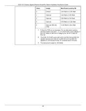
The total power budget is 193 Watts. 45 The DGS-1510-28P works with all D-Link 802.3af and 802.3at capable devices and with all non-802.3af and non-802.3at capable D-Link Access Points, IP Cameras and IP Phones. 9. Follow the PSE pin out standard. DGS-1510 Series Gigabit Ethernet SmartPro Switch Hardware Installation Guide...
The total power budget is 193 Watts. 45 The DGS-1510-28P works with all D-Link 802.3af and 802.3at capable devices and with all non-802.3af and non-802.3at capable D-Link Access Points, IP Cameras and IP Phones. 9. Follow the PSE pin out standard. DGS-1510 Series Gigabit Ethernet SmartPro Switch Hardware Installation Guide...
User Manual
Page 4
...Reference Guide 1. Introduction This manual's command descriptions are supported by using the information in a way that assumes that are based on the DGS-1510-28P switch. This manual is used in this manual. Keywords, in the separated list can be chosen. Parameters or values that are desired ... knowledge of the keywords in the command line, are to be entered exactly as "the Switch" within this switch, or from the D-Link website. Braces enclose alternative keywords separated by vertical bars. This convention is written in this manual are a further source of indicator. 1 ...
...Reference Guide 1. Introduction This manual's command descriptions are supported by using the information in a way that assumes that are based on the DGS-1510-28P switch. This manual is used in this manual. Keywords, in the separated list can be chosen. Parameters or values that are desired ... knowledge of the keywords in the command line, are to be entered exactly as "the Switch" within this switch, or from the D-Link website. Braces enclose alternative keywords separated by vertical bars. This convention is written in this manual are a further source of indicator. 1 ...
User Manual
Page 9
...physical port number 1. The Open Slot's ID is the physical port number of the stacking unit without the physical stack. The DGS-1510 Series doesn't support any open modules slots, thus this parameter is the ID of the port being configured. Lastly, the Port's... example, we 'll change the speed to recognize the command. DGS-1510 Series Gigabit Ethernet SmartPro Switch CLI Reference Guide DGS-1510-28P Gigabit Ethernet SmartPro Switch Command Line Interface Firmware: Build 1.10.001 Copyright(C) 2014 D-Link Corporation. After entering the Interface Configuration Mode for the Switch to ...
...physical port number 1. The Open Slot's ID is the physical port number of the stacking unit without the physical stack. The DGS-1510 Series doesn't support any open modules slots, thus this parameter is the ID of the port being configured. Lastly, the Port's... example, we 'll change the speed to recognize the command. DGS-1510 Series Gigabit Ethernet SmartPro Switch CLI Reference Guide DGS-1510-28P Gigabit Ethernet SmartPro Switch Command Line Interface Firmware: Build 1.10.001 Copyright(C) 2014 D-Link Corporation. After entering the Interface Configuration Mode for the Switch to ...