User Guide
Page 7
10/100 Fast Ethernet Switch User's Guide TABLE OF CONTENTS PREFACE ix Purpose...ix Audience ix Manual Organization x CHAPTER 1 : OVERVIEW 1 Introduction 1 Product Features 2 Packing List 2 Front Panel 3 Ports ...3 LED Indicators ...6 Rear Panel 7 Duplex Mode Switch 7 CHAPTER 2 : INSTALLATION 9 Installation Site 9 Installing on a Desktop or Shelf 10 Installing on a Wall 11 Connecting Power 12 Network Connections 12 10 (& 100Mbps) Mode Operations: Port 1 13 Preface vii
10/100 Fast Ethernet Switch User's Guide TABLE OF CONTENTS PREFACE ix Purpose...ix Audience ix Manual Organization x CHAPTER 1 : OVERVIEW 1 Introduction 1 Product Features 2 Packing List 2 Front Panel 3 Ports ...3 LED Indicators ...6 Rear Panel 7 Duplex Mode Switch 7 CHAPTER 2 : INSTALLATION 9 Installation Site 9 Installing on a Desktop or Shelf 10 Installing on a Wall 11 Connecting Power 12 Network Connections 12 10 (& 100Mbps) Mode Operations: Port 1 13 Preface vii
User Guide
Page 21
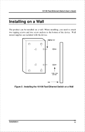
Wall mount supplies are included with the device. Figure 5 : Installing the 10/100 Fast Ethernet Switch on a wall. 10/100 Fast Ethernet Switch User's Guide Installing on a Wall The product can be installed on a Wall Installation 11 When installing, you need to attach two tapping screws and two screw anchors to the bottom of the device.
Wall mount supplies are included with the device. Figure 5 : Installing the 10/100 Fast Ethernet Switch on a wall. 10/100 Fast Ethernet Switch User's Guide Installing on a Wall The product can be installed on a Wall Installation 11 When installing, you need to attach two tapping screws and two screw anchors to the bottom of the device.

User Guide
Page 31
10/100 Fast Ethernet Switch User's Guide AUI Transceiver Connector The following table gives the pinouts for the AUI connector. Table B-2 : AUI Connector Pinouts Pin Circuit 1 CI-S 2 CI-A 3 DO-A 4 DI-S 5 DI-A 6 VC 7 CO-A 8 CO-S 9 CI-B 10 DO-B 11 DO-S 12 DI-B 13 VP 14 VS 15 CO-B Use Control IN Circuit Shield Control...
10/100 Fast Ethernet Switch User's Guide AUI Transceiver Connector The following table gives the pinouts for the AUI connector. Table B-2 : AUI Connector Pinouts Pin Circuit 1 CI-S 2 CI-A 3 DO-A 4 DI-S 5 DI-A 6 VC 7 CO-A 8 CO-S 9 CI-B 10 DO-B 11 DO-S 12 DI-B 13 VP 14 VS 15 CO-B Use Control IN Circuit Shield Control...