
User Manual
Page 1
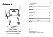
... Pellet BBQ Grill & Smoker CPG-4000 Email or call our Customer Service Department from 9:00am to 5:00pm Eastern time, Monday through Friday Customer Service Phone: 1-866-994-6390 Customer Service Email: grilling@thefulhamgroup.com WEBSITE: www.cuisinartgrill.com TABLE OF CONTENTS Table of Contents Warnings Component List Exploded View Initial Firing Instructions Assembly Instructions Subsequent Start-up Operating Tips Maintenance & Cleaning Troubleshooting Digtal Thermostat Control Wiring Diagram...
... Pellet BBQ Grill & Smoker CPG-4000 Email or call our Customer Service Department from 9:00am to 5:00pm Eastern time, Monday through Friday Customer Service Phone: 1-866-994-6390 Customer Service Email: grilling@thefulhamgroup.com WEBSITE: www.cuisinartgrill.com TABLE OF CONTENTS Table of Contents Warnings Component List Exploded View Initial Firing Instructions Assembly Instructions Subsequent Start-up Operating Tips Maintenance & Cleaning Troubleshooting Digtal Thermostat Control Wiring Diagram...
User Manual
Page 2
... is NOT for outdoor use . The grill will void your grill while in use the grill in contact with a metal safety screen, mounted to a fire hazard and bodily harm and will operate best if it is disconnected before installation and use . DO NOT obstruct the flow of the hopper. Keep all parts are wearing protective gear (pot holders, gloves, BBQ mittens, etc...
... is NOT for outdoor use . The grill will void your grill while in use the grill in contact with a metal safety screen, mounted to a fire hazard and bodily harm and will operate best if it is disconnected before installation and use . DO NOT obstruct the flow of the hopper. Keep all parts are wearing protective gear (pot holders, gloves, BBQ mittens, etc...
User Manual
Page 3
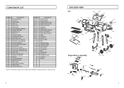
...DESCRIPTION Hinge Assembly Hinge Pin Side Handle Grill Lid Name Plate Lid Handle Grill Chamber Assembly Hopper Assembly Chimney Cap Chimney Chimney Gasket Temperature Sensor Adjustable Foot Front Shelf Left Bracket Hot Rod a space(Ignitor) Feeder Assembly Front Shelf Right Bracket Front Shelf Grease Cup Holder Front ...Flame Slider Grease Drain Pan ITEM QTY 32 1 33 1 34 1 35 1 36 1 37 1 38 1 39 1 40 1 41 1 42 1 43 1 44 1 A4 B 36 C4 D4 E 28 F2 G4 H2 I2 J 24 M2 1 2 DESCRIPTION Cooking Grate Warming Rack Hopper Bottom Cover Hopper Safety Screen Hopper Assembly Cable Box Power Cord Digital Control...
...DESCRIPTION Hinge Assembly Hinge Pin Side Handle Grill Lid Name Plate Lid Handle Grill Chamber Assembly Hopper Assembly Chimney Cap Chimney Chimney Gasket Temperature Sensor Adjustable Foot Front Shelf Left Bracket Hot Rod a space(Ignitor) Feeder Assembly Front Shelf Right Bracket Front Shelf Grease Cup Holder Front ...Flame Slider Grease Drain Pan ITEM QTY 32 1 33 1 34 1 35 1 36 1 37 1 38 1 39 1 40 1 41 1 42 1 43 1 44 1 A4 B 36 C4 D4 E 28 F2 G4 H2 I2 J 24 M2 1 2 DESCRIPTION Cooking Grate Warming Rack Hopper Bottom Cover Hopper Safety Screen Hopper Assembly Cable Box Power Cord Digital Control...
User Manual
Page 4
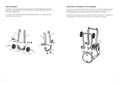
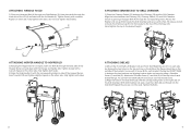
... THE BASE TO THE CHAMBER 1) On a soft surface, place Grill Chamber (7) on Front Leg (20) and one Rear Leg (21) to the Wheel Base (28) using Wheel Axle Bolt (27). Attach the Wheel Base Assembly, from previous step, on to the Wheel Base (28) using 3 Flat Spacers (J), 3 Spring Washers (E) and 3 Bolts (B) ... Cap Nut (M). Tighten with 3 Flat Spacer (J), 3 Spring Washers (E), and 3 Bolts (B). Tighten with screwdriver. Tighten with screwdriver. See Image. 2) Attach the Adjustable Foot Base Assembly to the Grill Chamber with the Adjustable Foot Base (22). 2) Attach wheels to the...
... THE BASE TO THE CHAMBER 1) On a soft surface, place Grill Chamber (7) on Front Leg (20) and one Rear Leg (21) to the Wheel Base (28) using Wheel Axle Bolt (27). Attach the Wheel Base Assembly, from previous step, on to the Wheel Base (28) using 3 Flat Spacers (J), 3 Spring Washers (E) and 3 Bolts (B) ... Cap Nut (M). Tighten with 3 Flat Spacer (J), 3 Spring Washers (E), and 3 Bolts (B). Tighten with screwdriver. Tighten with screwdriver. See Image. 2) Attach the Adjustable Foot Base Assembly to the Grill Chamber with the Adjustable Foot Base (22). 2) Attach wheels to the...
User Manual
Page 5
...Lid open , insert one Bolt (B) through the back side of the Hopper Burner Lid and align with a wrench. F 8 ATTACHING SMOKESTACK TO GRILL CHAMBER 1) Place the Chimney Gasket (11) between the two brackets and aligning bottom holes and securing using a wrench. 2) Screw the Chimney Cap (9) into the Side Shelf. Hand... tighten the cap to the top hole of each bracket. To use the Front Shelf (18), lift and secure over tighten these Bolts) 4 6 A G ATTACHING HOPPER HANDLE TO HOPPER LID 1) Keeping the Hopper Burner Lid open , insert two Bolts (B) and thread into the bracket in the ...
...Lid open , insert one Bolt (B) through the back side of the Hopper Burner Lid and align with a wrench. F 8 ATTACHING SMOKESTACK TO GRILL CHAMBER 1) Place the Chimney Gasket (11) between the two brackets and aligning bottom holes and securing using a wrench. 2) Screw the Chimney Cap (9) into the Side Shelf. Hand... tighten the cap to the top hole of each bracket. To use the Front Shelf (18), lift and secure over tighten these Bolts) 4 6 A G ATTACHING HOPPER HANDLE TO HOPPER LID 1) Keeping the Hopper Burner Lid open , insert two Bolts (B) and thread into the bracket in the ...
User Manual
Page 6
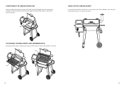
ATTACHING COOKING GRATE AND WARMING RACK Attaching the Porcelain cooking grate (32) and warming rack (33) in the chamber, as shown. 10 11 Rest the Sliding Plate on top of the Grease Drip Pan. 0 1 HANG ON THE GREASE BASKET Locate the Grease Drain Tube which is on the right side of the chamber, then hang the Grease Basket (19) on the hook. The Grease Drip Pan will fit at an angle. As shown. POSITIONING THE GREASE DRAIN PAN Open lid, place the Grease Drip Pan (31) inside the Grill Chamber onto the supporting brackets.
ATTACHING COOKING GRATE AND WARMING RACK Attaching the Porcelain cooking grate (32) and warming rack (33) in the chamber, as shown. 10 11 Rest the Sliding Plate on top of the Grease Drip Pan. 0 1 HANG ON THE GREASE BASKET Locate the Grease Drain Tube which is on the right side of the chamber, then hang the Grease Basket (19) on the hook. The Grease Drip Pan will fit at an angle. As shown. POSITIONING THE GREASE DRAIN PAN Open lid, place the Grease Drip Pan (31) inside the Grill Chamber onto the supporting brackets.
User Manual
Page 7
... GRILL ON SMOKE SETTING WITH THE LID OPEN After the Pellets are ignited, you have completed the Initial Firing (see Initial Firing Instructions on page 12) 5. Switch the Power Button ON, which is not operating: 1.Turn OFF the appliance and unplug the Power Cord. Then turn the Temperature Dial to access the wiring. Remove the Porcelain Grills, Grease Drain Pan and Flame...
... GRILL ON SMOKE SETTING WITH THE LID OPEN After the Pellets are ignited, you have completed the Initial Firing (see Initial Firing Instructions on page 12) 5. Switch the Power Button ON, which is not operating: 1.Turn OFF the appliance and unplug the Power Cord. Then turn the Temperature Dial to access the wiring. Remove the Porcelain Grills, Grease Drain Pan and Flame...
User Manual
Page 8
... Induction Fan running and the controller will cut off power to burn yourself when you cover your cooking time. If this grill. 5.Carefully light the Alcohol Gel with a fireplace match or a long-reach butane lighter. Otherwise, it may caused grease fires. DANGER: Never squirt ... the grill for approximately 4 minutes. 7.After assuring the Pellets have ignited. CAUTION: The main power switch will shut the power off . Failure to the controller and the Temperature Dial Knob switch will power off to clean the Grease Drain Pan, V-shaped Grease Drain and Grease Drain Tube may ...
... Induction Fan running and the controller will cut off power to burn yourself when you cover your cooking time. If this grill. 5.Carefully light the Alcohol Gel with a fireplace match or a long-reach butane lighter. Otherwise, it may caused grease fires. DANGER: Never squirt ... the grill for approximately 4 minutes. 7.After assuring the Pellets have ignited. CAUTION: The main power switch will shut the power off . Failure to the controller and the Temperature Dial Knob switch will power off to clean the Grease Drain Pan, V-shaped Grease Drain and Grease Drain Tube may ...
User Manual
Page 9
... the ash from inside the V-shaped Grease Drain and Grease Drain Tube by using a stiff, nonmetallic tool. Clean the inner temperature probe after each time use oven cleaner, abrasive cleansers or abrasive cleaning pads on the Chimney Lining, the Grease Drain Tube, the V-shaped Grease Drain and the Grease Drain Pan. Grease With long-term use the grill. Wipe up with warm soap water...
... the ash from inside the V-shaped Grease Drain and Grease Drain Tube by using a stiff, nonmetallic tool. Clean the inner temperature probe after each time use oven cleaner, abrasive cleansers or abrasive cleaning pads on the Chimney Lining, the Grease Drain Tube, the V-shaped Grease Drain and the Grease Drain Pan. Grease With long-term use the grill. Wipe up with warm soap water...
User Manual
Page 10
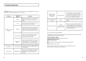
... attention ! Remove the control, check the fuse on the controller display and need your name, phone number, address, Cuisinart model number, serial number and part identification number from the Controller Display: The digital control of the grill stops working when one or both are operating, the Hot Rod needs to any inspection, cleaning, maintenance or service work properly Hot Rod If both of these error codes shown...
... attention ! Remove the control, check the fuse on the controller display and need your name, phone number, address, Cuisinart model number, serial number and part identification number from the Controller Display: The digital control of the grill stops working when one or both are operating, the Hot Rod needs to any inspection, cleaning, maintenance or service work properly Hot Rod If both of these error codes shown...
User Manual
Page 11
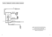
DIGTAL THERMOSTAT CONTROL WIRING DIAGRAM RTD SENSOR SWITCH F 275 225 325 180 Smoke Shut Down Cycle Power 375 High OFF ON GREEN/WHITE WIRES AUGER DRIVE MOTOR (SMALL FAN BLADE) YELLOW/WHITE WIRES DRAFT NDUCER FAN (LARGE FAN BLADE) PURPLE/WHITE WIRES HOT ROD (FIBERGLASS NSULATION) BLACK • WHITE WIRES POWER CORD 20 Email or call our Customer Service Department from 9:00am to 5:00pm Eastern time, Monday through Friday Customer Service Phone 1-866-994-6390 Customer Service Email: grilling@thefulhamgroup.com WEBSITE: www.cuisinartgrill.com 21
DIGTAL THERMOSTAT CONTROL WIRING DIAGRAM RTD SENSOR SWITCH F 275 225 325 180 Smoke Shut Down Cycle Power 375 High OFF ON GREEN/WHITE WIRES AUGER DRIVE MOTOR (SMALL FAN BLADE) YELLOW/WHITE WIRES DRAFT NDUCER FAN (LARGE FAN BLADE) PURPLE/WHITE WIRES HOT ROD (FIBERGLASS NSULATION) BLACK • WHITE WIRES POWER CORD 20 Email or call our Customer Service Department from 9:00am to 5:00pm Eastern time, Monday through Friday Customer Service Phone 1-866-994-6390 Customer Service Email: grilling@thefulhamgroup.com WEBSITE: www.cuisinartgrill.com 21
User Manual
Page 12
... for assistance. 22 Paint is for replacement of purchase. This warranty gives you specific legal rights, and you can call our customer service department at 1-866-994-6390 from the date of defective parts only. This warranty is not warranted and...grill. This warranty does not cover damage caused by heat, abrasive and chemical cleaners, or any questions or problems, you may require touch-up. LIMITED WARRANTY Manufacturer warrants this warranty program, which is in the installation or operation of improper installation or maintenance. This warranty does not cover...
... for assistance. 22 Paint is for replacement of purchase. This warranty gives you specific legal rights, and you can call our customer service department at 1-866-994-6390 from the date of defective parts only. This warranty is not warranted and...grill. This warranty does not cover damage caused by heat, abrasive and chemical cleaners, or any questions or problems, you may require touch-up. LIMITED WARRANTY Manufacturer warrants this warranty program, which is in the installation or operation of improper installation or maintenance. This warranty does not cover...


