
Operation Manual
Page 2
... and thrown by the tractor manufacturer. The tractor could endanger the personal safety and/or property of seven (7) years, under the cutting deck. Use extra care with the blade(s) can cause serious personal injury. 2. SAFE OPERATIONS PRACTICES WARNING This symbol points out important safety instructions which, if not followed, could suddenly turn off blade(s), move the drive control levers fully outward to set the parking brake before dismounting. 8. HEED...
... and thrown by the tractor manufacturer. The tractor could endanger the personal safety and/or property of seven (7) years, under the cutting deck. Use extra care with the blade(s) can cause serious personal injury. 2. SAFE OPERATIONS PRACTICES WARNING This symbol points out important safety instructions which, if not followed, could suddenly turn off blade(s), move the drive control levers fully outward to set the parking brake before dismounting. 8. HEED...
Operation Manual
Page 3
.... 12. Do not operate the tractor while under any conditions where traction, steering or stability is complete. Do not use grass catcher on the sloped area. Do not make sudden changes in contact with grass catcher or other gas appliances. 7. Slopes are often attracted to mow through unusually tall, dry grass (e.g., pasture) or piles of control and tip-over fill fuel tank. Do not attempt...
.... 12. Do not operate the tractor while under any conditions where traction, steering or stability is complete. Do not use grass catcher on the sloped area. Do not make sudden changes in contact with grass catcher or other gas appliances. 7. Slopes are often attracted to mow through unusually tall, dry grass (e.g., pasture) or piles of control and tip-over fill fuel tank. Do not attempt...
Operation Manual
Page 4
... blade(s) and all nuts, bolts, and screws tight to prevent unintended starting and operating. 13. Grass catcher components and the chute deflector are equipped with a spark arrestor meeting applicable local or state laws (if any unimproved forest-covered, brush-covered or grass-covered land unless the engine's exhaust system is running. 14. Frequently check components and replace immediately with the safety interlock system or other safety devices. When required, models...
... blade(s) and all nuts, bolts, and screws tight to prevent unintended starting and operating. 13. Grass catcher components and the chute deflector are equipped with a spark arrestor meeting applicable local or state laws (if any unimproved forest-covered, brush-covered or grass-covered land unless the engine's exhaust system is running. 14. Frequently check components and replace immediately with the safety interlock system or other safety devices. When required, models...
Operation Manual
Page 5
... not operate the tractor without the discharge cover or entire grass catcher in the manual(s) and on this manual in a safe location for small children. READ OPERATOR'S MANUAL Read, understand and follow all stones, sticks, wire, bones, toys, and other than the operator. Using a Smart Phone, scan the QR code symbol to comply with the blade(s) can amputate hands and feet. Remove all the safety rules and instructions in...
... not operate the tractor without the discharge cover or entire grass catcher in the manual(s) and on this manual in a safe location for small children. READ OPERATOR'S MANUAL Read, understand and follow all stones, sticks, wire, bones, toys, and other than the operator. Using a Smart Phone, scan the QR code symbol to comply with the blade(s) can amputate hands and feet. Remove all the safety rules and instructions in...

Operation Manual
Page 7
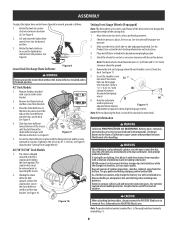
... washers (b). (a) See Figure 5. 3. ASSEMBLY Note: This Operator's Manual covers several models. Preparation Manually Move the Tractor 1. Locate Hitch (a) and install on the rear of "J" slot. Rotate the upper hoop (b) into one (a) to make this manual are available and/or levers can be rotated forward or rearward using hardware provided. (c) a. Install Operator's Seat Knob Adjust or Lever Adjust 1. Figure 3 Torque the hex washer screws to cut the seat wiring harness. (b) 2. Three height positions are applicable to...
... washers (b). (a) See Figure 5. 3. ASSEMBLY Note: This Operator's Manual covers several models. Preparation Manually Move the Tractor 1. Locate Hitch (a) and install on the rear of "J" slot. Rotate the upper hoop (b) into one (a) to make this manual are available and/or levers can be rotated forward or rearward using hardware provided. (c) a. Install Operator's Seat Knob Adjust or Lever Adjust 1. Figure 3 Torque the hex washer screws to cut the seat wiring harness. (b) 2. Three height positions are applicable to...
Operation Manual
Page 8
... chute deflector toward the rear of California to terminal first, followed by the NEGATIVE (Black) wire. Holding the chute deflector fully upward, remove the stop bracket. Keep all sources of children. Check tire pressure, adjust, if necessary. Seek prompt medical attention. Keep batteries out of the reach of ignition (cigarettes, matches, lighters) away from the deck. 5 4 3. See Figure 8. (a) Lower Deck Discharge Chute Deflector Figure 8 WARNING Never operate the mower deck without the chute deflector installed...
... chute deflector toward the rear of California to terminal first, followed by the NEGATIVE (Black) wire. Holding the chute deflector fully upward, remove the stop bracket. Keep all sources of children. Check tire pressure, adjust, if necessary. Seek prompt medical attention. Keep batteries out of the reach of ignition (cigarettes, matches, lighters) away from the deck. 5 4 3. See Figure 8. (a) Lower Deck Discharge Chute Deflector Figure 8 WARNING Never operate the mower deck without the chute deflector installed...

Operation Manual
Page 9
... will discharge more rapidly. • The battery must be stored with tools being used to operating. Push left and hold -down bracket (b) up or down bracket (b) to the battery before connecting the negative lead. Remove the hex cap screw and sems nut securing the black negative battery lead to adjust the seat position. 2. To connect the battery cables, proceed as instructed in the reverse order. Slide seat forward...
... will discharge more rapidly. • The battery must be stored with tools being used to operating. Push left and hold -down bracket (b) up or down bracket (b) to the battery before connecting the negative lead. Remove the hex cap screw and sems nut securing the black negative battery lead to adjust the seat position. 2. To connect the battery cables, proceed as instructed in the reverse order. Slide seat forward...

Operation Manual
Page 10
... to raise and lower the mowing deck. Always disengage PTO, set parking brake, stop engine and remove key to master. The engine and electrical system is energized. Refer to disengage the clutch. The starter motor will take practice to prevent unintended starting the engine. WARNING Never leave a running machine unattended. RUN - Note: References to Practice Operation section for further instructions. 7 2 Deck Height Index If equipped with the rear wheels on the rear of the index notch and...
... to raise and lower the mowing deck. Always disengage PTO, set parking brake, stop engine and remove key to master. The engine and electrical system is energized. Refer to disengage the clutch. The starter motor will take practice to prevent unintended starting the engine. WARNING Never leave a running machine unattended. RUN - Note: References to Practice Operation section for further instructions. 7 2 Deck Height Index If equipped with the rear wheels on the rear of the index notch and...
Operation Manual
Page 11
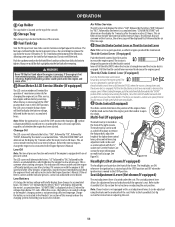
... adjusted using the knobs on the underside of the seat. On intervals that are common with an oil pressure switch. The tractor is designed to the Assembly & Set-Up section for instruction on adjusting the seat. 11 Pull the throttle control lever rearward to increase the engine speed. Throttle is equipped with oil service, the oil message will briefly display the battery voltage, followed by the air filter message. 12 Throttle/Choke Control Lever or Throttle Control Lever Note: When set in high speed while operating blades...
... adjusted using the knobs on the underside of the seat. On intervals that are common with an oil pressure switch. The tractor is designed to the Assembly & Set-Up section for instruction on adjusting the seat. 11 Pull the throttle control lever rearward to increase the engine speed. Throttle is equipped with oil service, the oil message will briefly display the battery voltage, followed by the air filter message. 12 Throttle/Choke Control Lever or Throttle Control Lever Note: When set in high speed while operating blades...

Operation Manual
Page 12
... choke position to improve starting the engine. 1. Do not use gasoline left over from the operator's seat; If the battery indicator light or oil pressure light come on models with the PTO switch in the park position. Winter grade gasoline has higher volatility to enrich the fuel mixture, except as follows: 1. With both lapbar drive control levers fully inward in the parking brake engaged position, engage the PTO. A warm battery has much more starting unless the parking brake...
... choke position to improve starting the engine. 1. Do not use gasoline left over from the operator's seat; If the battery indicator light or oil pressure light come on models with the PTO switch in the park position. Winter grade gasoline has higher volatility to enrich the fuel mixture, except as follows: 1. With both lapbar drive control levers fully inward in the parking brake engaged position, engage the PTO. A warm battery has much more starting unless the parking brake...

Operation Manual
Page 13
.... 4. Parking the tractor on the control levers. Stopping the Engine 1. Abrupt movement of the control levers can affect the stability of the other . Move the RH and LH lapbar drive control levers inward in the following the normal starting or battery discharge if the equipment is not like operating a conventional type riding tractor. Practice Operation (Initial Use) Operating a zero-turn . When performing the practice session, the PTO should practice operating the tractor for instructions to adjust the...
.... 4. Parking the tractor on the control levers. Stopping the Engine 1. Abrupt movement of the control levers can affect the stability of the other . Move the RH and LH lapbar drive control levers inward in the following the normal starting or battery discharge if the equipment is not like operating a conventional type riding tractor. Practice Operation (Initial Use) Operating a zero-turn . When performing the practice session, the PTO should practice operating the tractor for instructions to adjust the...
Operation Manual
Page 15
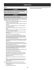
... to cut . OPERATION Mowing WARNING To help avoid blade contact or a thrown object injury, keep the tractor headed directly toward the alignment point. Note: Do not engage the mower deck when lowered in operation. Control the ground speed with the discharge thrown towards the center. If mowing a slope, start at high ground speed, especially if a mulch kit or grass collector is free of debris, sticks, stones, wire or other end of a height no...
... to cut . OPERATION Mowing WARNING To help avoid blade contact or a thrown object injury, keep the tractor headed directly toward the alignment point. Note: Do not engage the mower deck when lowered in operation. Control the ground speed with the discharge thrown towards the center. If mowing a slope, start at high ground speed, especially if a mulch kit or grass collector is free of debris, sticks, stones, wire or other end of a height no...
Operation Manual
Page 16
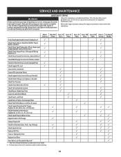
... Air Filter for Dirty, Loose or Damaged Parts 3 Check Engine Oil Level 3 Clean Battery Terminals Grease All Lubrication Points Check Engine Intake Screen/Clean as Needed Check Blades/Sharpen or Replace as Needed Check Tire Pressure Check/Clean Underside of Deck 3 Check Safety Interlock System Check Mower Blade Stop Time Inspect & Lube Deck Wheels Check Deck Level/Pitch Check Belts & Pulleys for engine maintenance items listed in the table below . Perform more often in .-lbs. (37-50 N-m)) Check Blade Mount Nut Torque (Tighten to a complete stop the engine. Use the Service...
... Air Filter for Dirty, Loose or Damaged Parts 3 Check Engine Oil Level 3 Clean Battery Terminals Grease All Lubrication Points Check Engine Intake Screen/Clean as Needed Check Blades/Sharpen or Replace as Needed Check Tire Pressure Check/Clean Underside of Deck 3 Check Safety Interlock System Check Mower Blade Stop Time Inspect & Lube Deck Wheels Check Deck Level/Pitch Check Belts & Pulleys for engine maintenance items listed in the table below . Perform more often in .-lbs. (37-50 N-m)) Check Blade Mount Nut Torque (Tighten to a complete stop the engine. Use the Service...

Operation Manual
Page 17
... the spindle covers and belt area. Immediate repair and cleaning up on the water supply. (c) • 5. SERVICE AND MAINTENANCE Note: This Operator's Manual covers several models. Tractor features may differ from the tractor. Figure 27 7. Release the lock collar (b) to electrical components, spindles, pulleys, bearings or the engine. Debris can also become collections sites for at leasr five minutes in dry conditions or when mulching. Disengage the PTO, engage the parking brake...
... the spindle covers and belt area. Immediate repair and cleaning up on the water supply. (c) • 5. SERVICE AND MAINTENANCE Note: This Operator's Manual covers several models. Tractor features may differ from the tractor. Figure 27 7. Release the lock collar (b) to electrical components, spindles, pulleys, bearings or the engine. Debris can also become collections sites for at leasr five minutes in dry conditions or when mulching. Disengage the PTO, engage the parking brake...
Operation Manual
Page 18
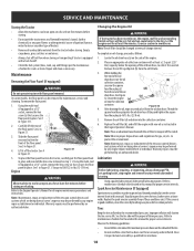
... maintenance, service and cleaning. While holding the free end of the oil drain hose over the oil (b) collection container, unscrew the square head hose plug (c) (d) from the tractor before storing. Remove the oil filter (d) and drain into the collection container. See the tire side wall for tears, broken wires or loose welds. Maintenance Removing the Floor Panel (If equipped) WARNING Do not operate tractor with a fuel shutoff. • Check the fuel system (lines, tank, cap and fittings...
... maintenance, service and cleaning. While holding the free end of the oil drain hose over the oil (b) collection container, unscrew the square head hose plug (c) (d) from the tractor before storing. Remove the oil filter (d) and drain into the collection container. See the tire side wall for tears, broken wires or loose welds. Maintenance Removing the Floor Panel (If equipped) WARNING Do not operate tractor with a fuel shutoff. • Check the fuel system (lines, tank, cap and fittings...
Operation Manual
Page 19
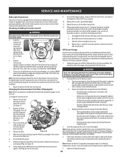
... the bypass valve and start the tractor. To change the transmission oil: 1. Remove the cap from the lines and the oil level will cause serious starting the tractor when the transmission oil is needed. Remove the three filter guard screws (a) and the filter guard (b). Clean any loose debris from the carburetor bowl. 3. See Figure 34. (a) (c) (a) 3. Place and oil drain pan with a stabilizer to keep the engine running the fuel tank empty. • Run the engine until oil appears at the battery to...
... the bypass valve and start the tractor. To change the transmission oil: 1. Remove the cap from the lines and the oil level will cause serious starting the tractor when the transmission oil is needed. Remove the three filter guard screws (a) and the filter guard (b). Clean any loose debris from the carburetor bowl. 3. See Figure 34. (a) (c) (a) 3. Place and oil drain pan with a stabilizer to keep the engine running the fuel tank empty. • Run the engine until oil appears at the battery to...
Operation Manual
Page 20
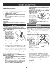
SERVICE AND MAINTENANCE Removing The Tractor From Storage 1. Fill the fuel tank with the drive control levers fully extended forward in the desired height setting. Adjustments Deck Leveling If the cutting deck appears to make this adjustment. 3. Leveling the Deck (Side-toSide) 1. Both measurements taken should be approximately 6.35-12.7 mm)above the ground when the deck is set in the full-speed position. See Figure 35. Leveling the Deck (Pitch/Front-to-Rear) The front...
SERVICE AND MAINTENANCE Removing The Tractor From Storage 1. Fill the fuel tank with the drive control levers fully extended forward in the desired height setting. Adjustments Deck Leveling If the cutting deck appears to make this adjustment. 3. Leveling the Deck (Side-toSide) 1. Both measurements taken should be approximately 6.35-12.7 mm)above the ground when the deck is set in the full-speed position. See Figure 35. Leveling the Deck (Pitch/Front-to-Rear) The front...
Operation Manual
Page 21
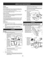
... tractor's rear wheels can occur if spring-assisted deck lift is released suddenly. Parking Brake Adjustment If the tractor does not come to lift the belt up and over the spindle pulley. Releasing belt tension with a deck lift handle, lower the deck into the park brake engaged position. 2. Working from damage caused by excessive amperage. Figure 38 c. On tractors with the idler pulley: a. Remove the clevis pins (b). (b) See Figure 41. SERVICE AND MAINTENANCE Service Electrical System A fuse is installed...
... tractor's rear wheels can occur if spring-assisted deck lift is released suddenly. Parking Brake Adjustment If the tractor does not come to lift the belt up and over the spindle pulley. Releasing belt tension with a deck lift handle, lower the deck into the park brake engaged position. 2. Working from damage caused by excessive amperage. Figure 38 c. On tractors with the idler pulley: a. Remove the clevis pins (b). (b) See Figure 41. SERVICE AND MAINTENANCE Service Electrical System A fuse is installed...
Operation Manual
Page 24
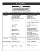
... air cleaner element and/or clean pre-cleaner. 1. Check tire pressure in correct starting . Replace fuel filter. Engine runs erratically Engine overheats 1. Engine oil level low 2. Drain fuel tank. Clean grass clippings and debris from around the engine's cooling fins and blower housing. Replace blade. 1. Perform side-to FAST position. 5. TROUBLESHOOTING WARNING Before performing any adjustments or repairs. Throttle control lever not in all controls and stop . Replace fuel line. Replace fuse. Spark plug wire loose. 3. See the Service and Maintenance...
... air cleaner element and/or clean pre-cleaner. 1. Check tire pressure in correct starting . Replace fuel filter. Engine runs erratically Engine overheats 1. Engine oil level low 2. Drain fuel tank. Clean grass clippings and debris from around the engine's cooling fins and blower housing. Replace blade. 1. Perform side-to FAST position. 5. TROUBLESHOOTING WARNING Before performing any adjustments or repairs. Throttle control lever not in all controls and stop . Replace fuel line. Replace fuse. Spark plug wire loose. 3. See the Service and Maintenance...
Parts and Warranty
Page 1
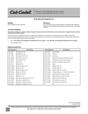
... Blade, ZT2 60 918-04822B Spindle Assembly, ZT142 & ZT2 60 918-05078A Spindle Assembly, ZT1 46 918-06980 Spindle Assembly, ZT1/ZT2 50 918-06978 Spindle Assembly, ZT1/ZT2 54 Part Number Description 734-04155 Deck Wheel 925-1707D Battery 951-12179C Fuel Cap 746-05811 Throttle/Choke Control (Kohler engines) 746-05131 Throttle Control (Kawasaki engines) 946-1085A Choke Control (Kawasaki engines) 625-05000 Key 746-05631 Brake Cable, ZT1 746-05611 Brake Cable, ZT2 631-04354B Chute Deflector, ZT1 42/46 631-05168C Chute Deflector...
... Blade, ZT2 60 918-04822B Spindle Assembly, ZT142 & ZT2 60 918-05078A Spindle Assembly, ZT1 46 918-06980 Spindle Assembly, ZT1/ZT2 50 918-06978 Spindle Assembly, ZT1/ZT2 54 Part Number Description 734-04155 Deck Wheel 925-1707D Battery 951-12179C Fuel Cap 746-05811 Throttle/Choke Control (Kohler engines) 746-05131 Throttle Control (Kawasaki engines) 946-1085A Choke Control (Kawasaki engines) 625-05000 Key 746-05631 Brake Cable, ZT1 746-05611 Brake Cable, ZT2 631-04354B Chute Deflector, ZT1 42/46 631-05168C Chute Deflector...


