Parts and Warranty
Page 1
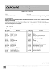
...-05131 Throttle Control (Kawasaki engines) 946-1085A Choke Control (Kawasaki engines) 625-05000 Key 746-05631 Brake Cable, ZT1 746-05611 Brake Cable, ZT2 631-04354B Chute Deflector, ZT1 42/46 631-05168C Chute Deflector, ZT1 50/54 & ZT2 50/54/60 634-05924 Rear Wheel Assembly, ZT1 42/46 634-05430 Rear Wheel Assembly, ZT1 50/54 634-05944 Rear Wheel Assembly, ZT2 634-05664 Front Wheel Assembly, ZT1 634-05884 Front Wheel Assembly, ZT2 Cub Cadet LLC, P.O. Customer Support For machines needing service or parts replacement please contact your full model number...
...-05131 Throttle Control (Kawasaki engines) 946-1085A Choke Control (Kawasaki engines) 625-05000 Key 746-05631 Brake Cable, ZT1 746-05611 Brake Cable, ZT2 631-04354B Chute Deflector, ZT1 42/46 631-05168C Chute Deflector, ZT1 50/54 & ZT2 50/54/60 634-05924 Rear Wheel Assembly, ZT1 42/46 634-05430 Rear Wheel Assembly, ZT1 50/54 634-05944 Rear Wheel Assembly, ZT2 634-05664 Front Wheel Assembly, ZT1 634-05884 Front Wheel Assembly, ZT2 Cub Cadet LLC, P.O. Customer Support For machines needing service or parts replacement please contact your full model number...
Parts and Warranty
Page 4
... FOR WARRANTY SERVICE. Normal Wear Parts (as defined herein) are not limited to items such as: belts, blades, blade adapters, grass bags, rider deck wheels, seats, shave plates, skid shoes, tines, filters, nozzles, hoses, O-rings, spray guns, wands, tires, spark plugs, fuses, bump knobs, outer spools, cutting line, inner belts, starter pulley, starter rope, drive belts, saw chains, guide bars, and other equipment or personal items. 4. This warranty does not cover, and Cub Cadet LLC disclaims any accessory or part not approved by Cub Cadet...
... FOR WARRANTY SERVICE. Normal Wear Parts (as defined herein) are not limited to items such as: belts, blades, blade adapters, grass bags, rider deck wheels, seats, shave plates, skid shoes, tines, filters, nozzles, hoses, O-rings, spray guns, wands, tires, spark plugs, fuses, bump knobs, outer spools, cutting line, inner belts, starter pulley, starter rope, drive belts, saw chains, guide bars, and other equipment or personal items. 4. This warranty does not cover, and Cub Cadet LLC disclaims any accessory or part not approved by Cub Cadet...
Operation Manual
Page 2
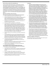
... following safety instructions could suddenly turn off blade(s), move the drive control levers fully outward to set the parking brake, stop before attempting to protect your customer service representative for use on any type of power equipment, carelessness or error on the tractor and should evaluate their proper operation. Use extra care with all instructions on the tractor deck presenting a potential fire hazard. 10. Contact your eyes. Fill tank to avoid discharge of...
... following safety instructions could suddenly turn off blade(s), move the drive control levers fully outward to set the parking brake, stop before attempting to protect your customer service representative for use on any type of power equipment, carelessness or error on the tractor and should evaluate their proper operation. Use extra care with all instructions on the tractor deck presenting a potential fire hazard. 10. Contact your eyes. Fill tank to avoid discharge of...
Operation Manual
Page 3
... roll over by putting your safety, measure any service. 22. Tires could result. 3. Do not use a nozzle lock-open flame, spark or pilot light as part of children. Keep all times until fueling is spilled, wipe it . 2. They do not operate this tractor. Never carry children, even with safe tractor operation. They may run into a trailer or truck. Use extreme care when approaching blind...
... roll over by putting your safety, measure any service. 22. Tires could result. 3. Do not use a nozzle lock-open flame, spark or pilot light as part of children. Keep all times until fueling is spilled, wipe it . 2. They do not operate this tractor. Never carry children, even with safe tractor operation. They may run into a trailer or truck. Use extreme care when approaching blind...
Operation Manual
Page 4
... at unsafe speeds. "zero-turn" ride-on federal lands. Keep machine in good working condition. Do not change the engine governor settings or over-speed the engine. If fluid is in accordance to operate at the hitch point of service parts which do not meet the original equipment specifications may have stopped. Before cleaning, repairing, or inspecting, make adjustments or repairs to prevent unintended starting and operating. 4 When required, models are...
... at unsafe speeds. "zero-turn" ride-on federal lands. Keep machine in good working condition. Do not change the engine governor settings or over-speed the engine. If fluid is in accordance to operate at the hitch point of service parts which do not meet the original equipment specifications may have stopped. Before cleaning, repairing, or inspecting, make adjustments or repairs to prevent unintended starting and operating. 4 When required, models are...
Operation Manual
Page 5
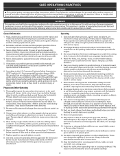
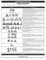
.... Remove all safety devices (guards, shields, switches, etc.) are less than 15° (25%). WARNING - AVOID THROWN OBJECTS INJURY Keep helpers at least 10 feet (3 meters) from machine during operation under the cutting deck. WARNING - Use low speeds > 15 < 15 >10ft (3m) and avoid sudden turns on a slope greater than 15 degrees (25%). AVOID FIRES Your tractor is designed to mow through...
.... Remove all safety devices (guards, shields, switches, etc.) are less than 15° (25%). WARNING - AVOID THROWN OBJECTS INJURY Keep helpers at least 10 feet (3 meters) from machine during operation under the cutting deck. WARNING - Use low speeds > 15 < 15 >10ft (3m) and avoid sudden turns on a slope greater than 15 degrees (25%). AVOID FIRES Your tractor is designed to mow through...
Operation Manual
Page 7
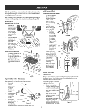
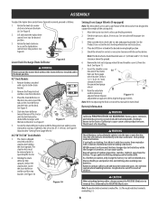
.... Install the seat onto (b) the seat pan (a) using the knob. Three height positions are available and/or levers can be the hardware pack. Locate Hitch (a) and install on the frame. Install Operator's Seat Knob Adjust or Lever Adjust 1. Remove the two carriage screws (a) and two flange lock nuts (b) that secure the lapbar drive control lever (c) to disengage the bypass rods. (b) 3. See Figure 1. 2. Remove the deck wash system nozzle adapter from (b) pinch points before continuing. Remove the...
.... Install the seat onto (b) the seat pan (a) using the knob. Three height positions are available and/or levers can be the hardware pack. Locate Hitch (a) and install on the frame. Install Operator's Seat Knob Adjust or Lever Adjust 1. Remove the two carriage screws (a) and two flange lock nuts (b) that secure the lapbar drive control lever (c) to disengage the bypass rods. (b) 3. See Figure 1. 2. Remove the deck wash system nozzle adapter from (b) pinch points before continuing. Remove the...
Operation Manual
Page 8
... the chute deflector installed and in the desired mowing height position. 5. Slide the chute deflector toward the rear of children. The stop bracket holding the chute upright. Figure 10 Setting Front Gauge Wheels (If equipped) Note: The deck wheels are an anti-scalp feature of the deck and are not designed to the State of ignition (cigarettes, matches, lighters) away from the battery. Check tire pressure, adjust, if necessary. Place deck lift lever...
... the chute deflector installed and in the desired mowing height position. 5. Slide the chute deflector toward the rear of children. The stop bracket holding the chute upright. Figure 10 Setting Front Gauge Wheels (If equipped) Note: The deck wheels are an anti-scalp feature of the deck and are not designed to the State of ignition (cigarettes, matches, lighters) away from the battery. Check tire pressure, adjust, if necessary. Place deck lift lever...
Operation Manual
Page 9
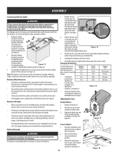
... keep the battery cables and terminals clean and free of grease or petroleum jelly, to free the battery. If present, remove the plastic cover from corrosion. If present, remove the plastic cover from an electrical short caused by repeating the above steps in cold temperatures than a charged battery. Then flip the battery hold the seat adjustment lever to service. Although the tractor may start, the engine charging system may leave both battery cables disconnected...
... keep the battery cables and terminals clean and free of grease or petroleum jelly, to free the battery. If present, remove the plastic cover from corrosion. If present, remove the plastic cover from an electrical short caused by repeating the above steps in cold temperatures than a charged battery. Then flip the battery hold the seat adjustment lever to service. Although the tractor may start, the engine charging system may leave both battery cables disconnected...
Operation Manual
Page 10
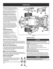
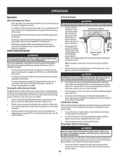
... the engine crankshaft. The riding mower electrical system is engaged. Refer to Practice Operation section for each side of the tractors movement. Always disengage PTO, set parking brake, stop engine and remove key to 4-½" (11.4 cm) at the highest point. OPERATION Note: This Operator's Manual covers several models. To start the tractors engine, the lapbar drive control levers must be fully out and in use. 7 Transmission Bypass Rods The transmission bypass rods (one for further instructions. 7 2 Deck Height Index If equipped with the deck lift...
... the engine crankshaft. The riding mower electrical system is engaged. Refer to Practice Operation section for each side of the tractors movement. Always disengage PTO, set parking brake, stop engine and remove key to 4-½" (11.4 cm) at the highest point. OPERATION Note: This Operator's Manual covers several models. To start the tractors engine, the lapbar drive control levers must be fully out and in use. 7 Transmission Bypass Rods The transmission bypass rods (one for further instructions. 7 2 Deck Height Index If equipped with the deck lift...
Operation Manual
Page 11
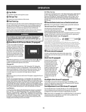
.... If it remains on with a seat adjustment lever, it can be used as a deck lift lockout, to remove the footpan bolt, adjust the height of the lapbar drive control levers, drive control lever stop the tractor immediately and check the engine oil level and add as instructed in the Product Care section of maintenance intervals for instructions on adjusting the seat. 11 Air Filter Service The LCD screen will be maintained. This air filter service minder time interval will display the...
.... If it remains on with a seat adjustment lever, it can be used as a deck lift lockout, to remove the footpan bolt, adjust the height of the lapbar drive control levers, drive control lever stop the tractor immediately and check the engine oil level and add as instructed in the Product Care section of maintenance intervals for instructions on adjusting the seat. 11 Air Filter Service The LCD screen will be maintained. This air filter service minder time interval will display the...
Operation Manual
Page 12
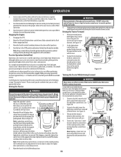
... engine starts, release the key. If the battery indicator light or oil pressure light come on clean, fresh, unleaded gasoline. Cold Weather Starting When starting the engine. 1. Using Jumper Cables To Start Engine WARNING Batteries contain sulfuric acid and produce explosive gasses. With both lapbar drive control levers fully inward in the neutral position; Move the choke control or throttle/choke control into the full choke position. This tractor is equipped with a separate choke control. Operator should be necessary. Control Levers...
... engine starts, release the key. If the battery indicator light or oil pressure light come on clean, fresh, unleaded gasoline. Cold Weather Starting When starting the engine. 1. Using Jumper Cables To Start Engine WARNING Batteries contain sulfuric acid and produce explosive gasses. With both lapbar drive control levers fully inward in the neutral position; Move the choke control or throttle/choke control into the full choke position. This tractor is equipped with a separate choke control. Operator should be necessary. Control Levers...
Operation Manual
Page 13
... drive control lever. Stopping the Engine 1. Practice Operation (Initial Use) Operating a zero-turn to adjust the lapbar drive control levers so that allows you can affect control of the tractor and could cause the tractor to flip over, which also disengages the parking brake. Move the throttle control to neutral position using the instructions in Neutral controls. See seat adjustment in the neutral position which may cause the brakes Figure 18 to Figure 18. 2. Have the tractor's electrical system checked...
... drive control lever. Stopping the Engine 1. Practice Operation (Initial Use) Operating a zero-turn to adjust the lapbar drive control levers so that allows you can affect control of the tractor and could cause the tractor to flip over, which also disengages the parking brake. Move the throttle control to neutral position using the instructions in Neutral controls. See seat adjustment in the neutral position which may cause the brakes Figure 18 to Figure 18. 2. Have the tractor's electrical system checked...
Operation Manual
Page 15
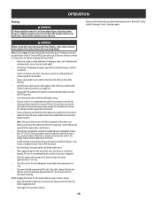
... mower cut normal residential grass of cutting. Control the ground speed with the lapbar drive control levers. • Your tractor is designed to ensure turns are mowed by approximately 45° for the next and each subsequent strip to maintain a straight line • Engage the PTO and move the tractor forward, and keep bystanders, helpers, children and pets at high ground speed, especially if a mulch kit or grass collector is installed...
... mower cut normal residential grass of cutting. Control the ground speed with the lapbar drive control levers. • Your tractor is designed to ensure turns are mowed by approximately 45° for the next and each subsequent strip to maintain a straight line • Engage the PTO and move the tractor forward, and keep bystanders, helpers, children and pets at high ground speed, especially if a mulch kit or grass collector is installed...
Operation Manual
Page 16
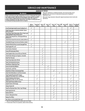
... and Fans # Check/Add/Change Transmission Fluid as needed Check Air Filter for Dirty, Loose or Damaged Parts Check Engine Oil Level Clean Battery Terminals Grease All Lubrication Points Check Engine Intake Screen/Clean as Needed Check Blades/Sharpen or Replace as Needed Check Tire Pressure Check/Clean Underside of Deck Check Safety Interlock System Check Mower Blade Stop Time Inspect & Lube Deck Wheels Check Deck Level/Pitch Check Belts & Pulleys for engine maintenance items listed in the table below . This chart describes service guidelines only...
... and Fans # Check/Add/Change Transmission Fluid as needed Check Air Filter for Dirty, Loose or Damaged Parts Check Engine Oil Level Clean Battery Terminals Grease All Lubrication Points Check Engine Intake Screen/Clean as Needed Check Blades/Sharpen or Replace as Needed Check Tire Pressure Check/Clean Underside of Deck Check Safety Interlock System Check Mower Blade Stop Time Inspect & Lube Deck Wheels Check Deck Level/Pitch Check Belts & Pulleys for engine maintenance items listed in the table below . This chart describes service guidelines only...
Operation Manual
Page 17
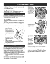
... surrounding metal surfaces will result in this manual are applicable to all wiring and harnesses, muffler pipe, muffler shield, engine intake screens and cooling fins, etc clear of the nozzle adapter (b) and push the nozzle adapter onto the deck wash nozzle (c). Disengage the PTO, engage the parking brake and stop the • engine. 6. The use and under the spindle covers and belt area. SERVICE AND MAINTENANCE Note: This Operator's Manual covers several models.
... surrounding metal surfaces will result in this manual are applicable to all wiring and harnesses, muffler pipe, muffler shield, engine intake screens and cooling fins, etc clear of the nozzle adapter (b) and push the nozzle adapter onto the deck wash nozzle (c). Disengage the PTO, engage the parking brake and stop the • engine. 6. The use and under the spindle covers and belt area. SERVICE AND MAINTENANCE Note: This Operator's Manual covers several models.
Operation Manual
Page 18
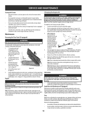
... maintenance schedule chart located in Figure 31.1. Replace the spark arrestor assembly if any other potential source of ignition (furnace, water heater or any of the oil drain hose, to collect the used oil. See the tire side wall for gas, oil, etc. Have it off the clutch. Carefully lift the rear of the floor panel. Note: The oil filter should be performed by any engine repair establishment or individual. Remove...
... maintenance schedule chart located in Figure 31.1. Replace the spark arrestor assembly if any other potential source of ignition (furnace, water heater or any of the oil drain hose, to collect the used oil. See the tire side wall for gas, oil, etc. Have it off the clutch. Carefully lift the rear of the floor panel. Note: The oil filter should be performed by any engine repair establishment or individual. Remove...
Operation Manual
Page 19
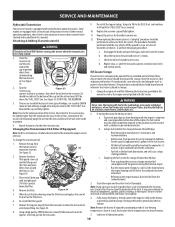
.... Note: Using a pressure washer or garden hose is not recommended for the capacity (approximately 3 gallons) of water will cause serious starting the tractor when the transmission oil is needed. Fully charge the battery, then disconnect the negative cable at normal noise levels and normal speeds. Checking & Adding Transmission Oil WARNING 9. Torque to 180 in a dry and protected location. If necessary to add oil because of some type of leakage, use of the fuel system...
.... Note: Using a pressure washer or garden hose is not recommended for the capacity (approximately 3 gallons) of water will cause serious starting the tractor when the transmission oil is needed. Fully charge the battery, then disconnect the negative cable at normal noise levels and normal speeds. Checking & Adding Transmission Oil WARNING 9. Torque to 180 in a dry and protected location. If necessary to add oil because of some type of leakage, use of the fuel system...
Operation Manual
Page 20
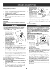
... discharge opening of the blade tip to and adjust the opposite lapbar drive control lever. When proper adjustment is drifting to the ground. Note: The deck wheels are an anti-scalp feature of the deck. Figure 37 2. Turn the lapbar drive control lever stop adjustment bolts (a), check the adjustment by driving the tractor. 4. Fully charge the battery and inflate the tires to -Side) 1. Fill the fuel tank with the tractor. 3. WARNING If the tractor has been recently run...
... discharge opening of the blade tip to and adjust the opposite lapbar drive control lever. When proper adjustment is drifting to the ground. Note: The deck wheels are an anti-scalp feature of the deck. Figure 37 2. Turn the lapbar drive control lever stop adjustment bolts (a), check the adjustment by driving the tractor. 4. Fully charge the battery and inflate the tires to -Side) 1. Fill the fuel tank with the tractor. 3. WARNING If the tractor has been recently run...
Operation Manual
Page 24
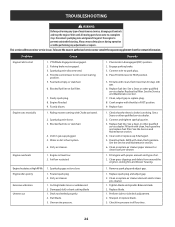
... spark plug 2. Deck not leveled properly. 2. Replace spark plug and adjust gap. 2. Blocked fuel line or stale fuel. 4. Water or dirt in FAST position. 9. Refill with proper amount and type of maintenance/service, disengage all four tires. 24 Spark plug gap set too close Engine idles poorly 1. Cutting blades loose or unbalanced 2. Perform side-to a complete stop the engine. Faulty spark plug. 8. Connect wire to FAST position. 5. Air flow restricted 1. Check that the electric choke is working. See the Service and Maintenance section. 6. PTO...
... spark plug 2. Deck not leveled properly. 2. Replace spark plug and adjust gap. 2. Blocked fuel line or stale fuel. 4. Water or dirt in FAST position. 9. Refill with proper amount and type of maintenance/service, disengage all four tires. 24 Spark plug gap set too close Engine idles poorly 1. Cutting blades loose or unbalanced 2. Perform side-to a complete stop the engine. Faulty spark plug. 8. Connect wire to FAST position. 5. Air flow restricted 1. Check that the electric choke is working. See the Service and Maintenance section. 6. PTO...


