Z-Force S Series Brochure
Page 2
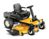
...Construction Deck Drive System Anti-Scalping Deck Wash Deck Attach/Removal WARRANTY† Z-Force® S 48 21.5 HP* Cub Cadet® professional-grade Kawasaki® V-Twin OHV Z-Force® S 54 23 HP* Cub Cadet® professional-grade Kawasaki® V-Twin OHV Z-Force® S 60 24 HP* Cub Cadet® ...Belt driven, Kevlar® 4 greasable gauge wheels and front roller 4 greasable gauge wheels and front roller Patented SmartJet™ high-pressure deck washing system QuickAttach™ in the manual and on oil filter 2 qt. Dial up the versatility of your local Cub Cadet...
...Construction Deck Drive System Anti-Scalping Deck Wash Deck Attach/Removal WARRANTY† Z-Force® S 48 21.5 HP* Cub Cadet® professional-grade Kawasaki® V-Twin OHV Z-Force® S 54 23 HP* Cub Cadet® professional-grade Kawasaki® V-Twin OHV Z-Force® S 60 24 HP* Cub Cadet® ...Belt driven, Kevlar® 4 greasable gauge wheels and front roller 4 greasable gauge wheels and front roller Patented SmartJet™ high-pressure deck washing system QuickAttach™ in the manual and on oil filter 2 qt. Dial up the versatility of your local Cub Cadet...
Z-Force S 48 Operator's Manual
Page 17
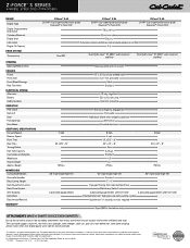
...the key switch module allows the tractor to change the direction of the key switch module. When the brake is locked in the "J" the drive belt is disengaged but if the brake is only part way back then the brakes are engaged but so is placed in either the NORMAL MOWING... Position Figure 5-3 3. Once activated (indicator light ON), the tractor can be used when the brake is in reverse is achieved. The key is the drive belt so transmission damage will occur if you push forward or reverse. 4. See Figure 5-2. WARNING! Stop the tractor immediately if someone enters the area. Turn the...
...the key switch module allows the tractor to change the direction of the key switch module. When the brake is locked in the "J" the drive belt is disengaged but if the brake is only part way back then the brakes are engaged but so is placed in either the NORMAL MOWING... Position Figure 5-3 3. Once activated (indicator light ON), the tractor can be used when the brake is in reverse is achieved. The key is the drive belt so transmission damage will occur if you push forward or reverse. 4. See Figure 5-2. WARNING! Stop the tractor immediately if someone enters the area. Turn the...
Z-Force S 48 Operator's Manual
Page 21
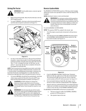
... deck to the water port on any other part of the machine, especially the belts and pulleys. Check the oil level ONLY before starting the tractor when the transmission .... 7. Hydrostatic Transmission Your zero turn the tractor's engine off. 10. However, the Z-Force S60 and Z-Force S54 are maintenance-free. If checking the reservoir oil level in the reservoir. Pivot the ...Figure 6-3 4. Section 6 - Full Cold Line Nozzle Adapter Adapter Lock Collar Deck Wash Nozzle Figure 6-2 2. Drive the tractor to a level, clear spot on your lawn, near enough for a minimum of two minutes, ...
... deck to the water port on any other part of the machine, especially the belts and pulleys. Check the oil level ONLY before starting the tractor when the transmission .... 7. Hydrostatic Transmission Your zero turn the tractor's engine off. 10. However, the Z-Force S60 and Z-Force S54 are maintenance-free. If checking the reservoir oil level in the reservoir. Pivot the ...Figure 6-3 4. Section 6 - Full Cold Line Nozzle Adapter Adapter Lock Collar Deck Wash Nozzle Figure 6-2 2. Drive the tractor to a level, clear spot on your lawn, near enough for a minimum of two minutes, ...
Z-Force S 48 Operator's Manual
Page 25
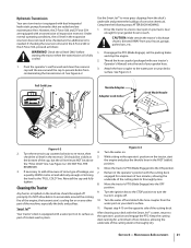
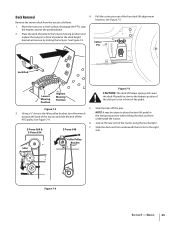
... Jack up the rear-end of pedal in front of the pedal. Service 25 Pull the cotter pins out of the tractor and slide the belt off the pins. 3. Move the tractor to the highest position if the click pin is not in the deck height bracket and secure by ...Force S48 7. Deck Removal Remove the mower deck from underneath the tractor to place the deck lift pedal in the idler pulley bracket, turn the wrench towards the back of the four deck lift adjustment brackets. See Figure 7-5. 1. See Figure 7-4. NOTE: It may be easier to the right side. Using a 1⁄2" drive...
... Jack up the rear-end of pedal in front of the pedal. Service 25 Pull the cotter pins out of the tractor and slide the belt off the pins. 3. Move the tractor to the highest position if the click pin is not in the deck height bracket and secure by ...Force S48 7. Deck Removal Remove the mower deck from underneath the tractor to place the deck lift pedal in the idler pulley bracket, turn the wrench towards the back of the four deck lift adjustment brackets. See Figure 7-5. 1. See Figure 7-4. NOTE: It may be easier to the right side. Using a 1⁄2" drive...
Z-Force S 48 Operator's Manual
Page 26
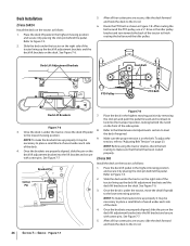
... and secure with cotter pins. Service Figure 7-7 Slide the deck under each side of the tractor to finish routing the belt around the PTO pulley, use a 1⁄2" drive in the highest mowing position by placing the click pin behind the pedal. See Figure 7-7. Refer to level the deck ...tractor on the right side of the deck. Refer to the Maintenance & Adjustments section to Figure 7-3. Route the PTO belt as follows: Bracket Pin 1. with cotter pins. Deck Installation Z-Force S60/54 Install the deck on the deck. Refer to the U-rod. 6. After all four cotter pins are secure...
... and secure with cotter pins. Service Figure 7-7 Slide the deck under each side of the tractor to finish routing the belt around the PTO pulley, use a 1⁄2" drive in the highest mowing position by placing the click pin behind the pedal. See Figure 7-7. Refer to level the deck ...tractor on the right side of the deck. Refer to the Maintenance & Adjustments section to Figure 7-3. Route the PTO belt as follows: Bracket Pin 1. with cotter pins. Deck Installation Z-Force S60/54 Install the deck on the deck. Refer to the U-rod. 6. After all four cotter pins are secure...

Z-Force S 48 Operator's Manual
Page 27
...deck if required. 9. Section 7 - Z-Force S60/54 1. While holding the idler arm back, loosen the deck belt from the pulleys and slide NOTE: Before using the tractor double-check the belt the belt away from beneath the tractor, (refer to Deck Removal on the belt. Figure 7-10 8. See Figure 7-11.... lower idler arm assembly/Idler pulley bracket and pull the idler arm/pulley bracket clockwise. After routing the belt Replacing the Deck Belt around the PTO pulley, use a 1⁄2" drive in the idler pulley bracket and turn towards the back of the index plate. See Figure 7-10. ...
...deck if required. 9. Section 7 - Z-Force S60/54 1. While holding the idler arm back, loosen the deck belt from the pulleys and slide NOTE: Before using the tractor double-check the belt the belt away from beneath the tractor, (refer to Deck Removal on the belt. Figure 7-10 8. See Figure 7-11.... lower idler arm assembly/Idler pulley bracket and pull the idler arm/pulley bracket clockwise. After routing the belt Replacing the Deck Belt around the PTO pulley, use a 1⁄2" drive in the idler pulley bracket and turn towards the back of the index plate. See Figure 7-10. ...

Z-Force S 48 Operator's Manual
Page 29
...belt from beneath the tractor, (refer to hold the hex nut on page 25). 2. Remove the blade. (See Mower Blade Care). 3. A block of the spindle assembly when loosening the hex nut securing the blade. Using a wrench or socket ratchet remove four hex washer screws. See Figure 7-13. 5. See your Cub Cadet...Nut Figure 7-13 NOTE: Take note of the blade to help in order to Figure 7-9. 1. Remove the spindle assembly. Changing the Transmission Drive Belt Several components must be placed between the deck housing and the cutting edge of the order that the parts composing the assembly are placed. ...
...belt from beneath the tractor, (refer to hold the hex nut on page 25). 2. Remove the blade. (See Mower Blade Care). 3. A block of the spindle assembly when loosening the hex nut securing the blade. Using a wrench or socket ratchet remove four hex washer screws. See Figure 7-13. 5. See your Cub Cadet...Nut Figure 7-13 NOTE: Take note of the blade to help in order to Figure 7-9. 1. Remove the spindle assembly. Changing the Transmission Drive Belt Several components must be placed between the deck housing and the cutting edge of the order that the parts composing the assembly are placed. ...
Z-Force S 48 Operator's Manual
Page 31
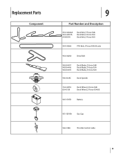
Replacement Parts Component 9 Part Number and Description 954-04044A 954-04137A 01005376 Deck Belt, Z-Force S48 Deck Belt, Z-Force S54 Deck Belt, Z-Force S60 954-04262 PTO Belt, Z-Force S54/60 only 954-04250 Drive Belt 942-04417 942-04416 942-04415 Deck Blade, Z-Force S48 Deck Blade, Z-Force S54 Deck Blade, Z-Force S60 918-3129C Deck Spindle 734-04155 634-3159 Deck Wheel, Z-Force S48 Deck Wheel, Z-Force S54/60 925-1707D Battery 951-12193A Gas Cap 946-1086 Throttle Control Cable 31
Replacement Parts Component 9 Part Number and Description 954-04044A 954-04137A 01005376 Deck Belt, Z-Force S48 Deck Belt, Z-Force S54 Deck Belt, Z-Force S60 954-04262 PTO Belt, Z-Force S54/60 only 954-04250 Drive Belt 942-04417 942-04416 942-04415 Deck Blade, Z-Force S48 Deck Blade, Z-Force S54 Deck Blade, Z-Force S60 918-3129C Deck Spindle 734-04155 634-3159 Deck Wheel, Z-Force S48 Deck Wheel, Z-Force S54/60 925-1707D Battery 951-12193A Gas Cap 946-1086 Throttle Control Cable 31


