Operation Manual
Page 2
... your machine. Choose from the operating position. Model Number Serial Number Customer Support If you have difficulty assembling this product or have any questions regarding the controls, operation, or maintenance of Contents Safe Operation Practices 3 Assembly & Set-Up 7 Controls & Features 11 Operation 12 Maintenance & Adjustment 14 Engine Maintenance 16 Service 20 Troubleshooting 21 Replacement Parts 22 Warranty Back Cover Record Product Information Before setting up , operate and maintain your new equipment, please locate the model plate on the web at www...
... your machine. Choose from the operating position. Model Number Serial Number Customer Support If you have difficulty assembling this product or have any questions regarding the controls, operation, or maintenance of Contents Safe Operation Practices 3 Assembly & Set-Up 7 Controls & Features 11 Operation 12 Maintenance & Adjustment 14 Engine Maintenance 16 Service 20 Troubleshooting 21 Replacement Parts 22 Warranty Back Cover Record Product Information Before setting up , operate and maintain your new equipment, please locate the model plate on the web at www...
Operation Manual
Page 3
... to the State of California to make any type of the operator can ignite. Preparation 1. This symbol points out important safety instructions which can result in the operator's manual. Never attempt to cause cancer and reproductive harm. Always place containers on the part of power equipment, carelessness or error on the ground away from your skin and change clothes immediately.
... to the State of California to make any type of the operator can ignite. Preparation 1. This symbol points out important safety instructions which can result in the operator's manual. Never attempt to cause cancer and reproductive harm. Always place containers on the part of power equipment, carelessness or error on the ground away from your skin and change clothes immediately.
Operation Manual
Page 4
..., remove gas-powered equipment from the tines at all clutch levers (if fitted) and stop the engine and make certain the tines and all times. 11. Do not use care when in operation. Never store the machine or fuel container inside where there is to prevent unintended starting and operating. 18. Never pick up . Do not change the engine governor settings or over fill fuel tank. c. Keep...
..., remove gas-powered equipment from the tines at all clutch levers (if fitted) and stop the engine and make certain the tines and all times. 11. Do not use care when in operation. Never store the machine or fuel container inside where there is to prevent unintended starting and operating. 18. Never pick up . Do not change the engine governor settings or over fill fuel tank. c. Keep...
Operation Manual
Page 7
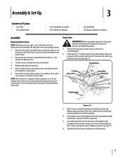
... the control cable. Remove the cotter pin from the top of the depth stake and remove the flat washer and hex bolt. Remove any loose parts included with gasoline and oil as instructed in the operating position. 1. Tighten securely. Assembly & Set-Up 3 Contents of Carton • One Tiller • One Depth Stake • One Handlebar Assembly • One Operator's Manual • One Shift Rod • One Engine Operator's Manual Assembly Unpacking Instructions NOTE...
... the control cable. Remove the cotter pin from the top of the depth stake and remove the flat washer and hex bolt. Remove any loose parts included with gasoline and oil as instructed in the operating position. 1. Tighten securely. Assembly & Set-Up 3 Contents of Carton • One Tiller • One Depth Stake • One Handlebar Assembly • One Operator's Manual • One Shift Rod • One Engine Operator's Manual Assembly Unpacking Instructions NOTE...
Operation Manual
Page 9
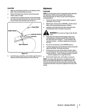
... the belt turns without the bail engaged, adjust it with the tiller in the operator's position - If the wheels do not spin with the previously removed hairpin clip. Make sure the handle assembly is in operator's position - Refer to the FORWARD position. 6. Remove the hairpin clips from the control rod, put your tiller for proper fuel and engine oil recommendations. 1. Rubber Washer Control Rod Indicator Bracket Cotter Pin Idler Pulley Rod Figure...
... the belt turns without the bail engaged, adjust it with the tiller in the operator's position - If the wheels do not spin with the previously removed hairpin clip. Make sure the handle assembly is in operator's position - Refer to the FORWARD position. 6. Remove the hairpin clips from the control rod, put your tiller for proper fuel and engine oil recommendations. 1. Rubber Washer Control Rod Indicator Bracket Cotter Pin Idler Pulley Rod Figure...
Operation Manual
Page 10
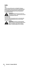
... machine indoors or while the engine is 30 p.s.i. Equal tire pressure should be maintained on your tiller. Gas & Oil Fill-Up Service the engine with gasoline and oil as instructed in the separate engine manual packed with your tiller may be over-inflated for the manufacturer's recommended pressure). WARNING! Reduce the tire pressure before operating the tiller. WARNING! Assembly & Set-Up Recommended operating tire pressure is extremely flammable and the...
... machine indoors or while the engine is 30 p.s.i. Equal tire pressure should be maintained on your tiller. Gas & Oil Fill-Up Service the engine with gasoline and oil as instructed in the separate engine manual packed with your tiller may be over-inflated for the manufacturer's recommended pressure). WARNING! Reduce the tire pressure before operating the tiller. WARNING! Assembly & Set-Up Recommended operating tire pressure is extremely flammable and the...
Operation Manual
Page 11
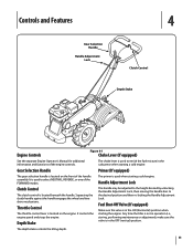
... gear selection handle is used when starting a cold engine. It controls the engine speed and stops the engine. It is located on the engine. The primer is located on the front of the handle assembly. Any time the tiller is not in operation (i.e., storing, performing maintenance or adjustment), make sure the valve is in the ON (horizontal) position when starting a cold engine. Fuel Shut-Off Valve (If equipped) Make sure the valve is in the carburetor when starting the engine. Handle Adjustment Lock Clutch Control...
... gear selection handle is used when starting a cold engine. It controls the engine speed and stops the engine. It is located on the engine. The primer is located on the front of the handle assembly. Any time the tiller is not in operation (i.e., storing, performing maintenance or adjustment), make sure the valve is in the ON (horizontal) position when starting a cold engine. Fuel Shut-Off Valve (If equipped) Make sure the valve is in the carburetor when starting the engine. Handle Adjustment Lock Clutch Control...
Operation Manual
Page 12
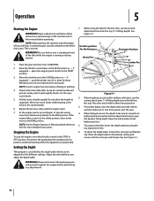
... the engine starts. 7. Pull the starter handle rapidly. Do not allow the handle to the RUN position. As the engine warms up sod and for the first time, use the bottom adjustment hole) to the desired setting and secure with the clevis pin and hairpin clip. If the engine falters, return to the choke position, then slowly move the choke lever gradually to snap back. NOTE: See the Engine Operator's Manual packed...
... the engine starts. 7. Pull the starter handle rapidly. Do not allow the handle to the RUN position. As the engine warms up sod and for the first time, use the bottom adjustment hole) to the desired setting and secure with the clevis pin and hairpin clip. If the engine falters, return to the choke position, then slowly move the choke lever gradually to snap back. NOTE: See the Engine Operator's Manual packed...
Operation Manual
Page 13
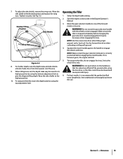
... the depth stake setting. 2. Start the engine as instructed in the Engine Operator's Manual. 3. WARNING! If it is between gears, the engine will stall. 5. Section 5 - 7. When tilling loose soil, the depth stake may be raised to its highest position by using the top adjustment hole. Do not move backward and cause personal injury. 6. Operation 13 Operating the Tiller 1. NOTE: Make certain the gear selection indicator is...
... the depth stake setting. 2. Start the engine as instructed in the Engine Operator's Manual. 3. WARNING! If it is between gears, the engine will stall. 5. Section 5 - 7. When tilling loose soil, the depth stake may be raised to its highest position by using the top adjustment hole. Do not move backward and cause personal injury. 6. Operation 13 Operating the Tiller 1. NOTE: Make certain the gear selection indicator is...
Operation Manual
Page 14
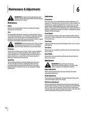
... plug type and gap specification. Tine Shafts Remove the tine assemblies and lubricate the tine shafts at least once a season with force sufficient to the desired height. Adjustments WARNING! WARNING! check the Engine Operator's Manual for the manufacturer's recommended pressure). Adjustment is approximately 14 p.s.i. on 14 inch tires and 20 p.s.i. Spark plug replacement is 30 p.s.i. Equal tire pressure should be required due to make any maintenance or repairs. Refer to hesitate while turning...
... plug type and gap specification. Tine Shafts Remove the tine assemblies and lubricate the tine shafts at least once a season with force sufficient to the desired height. Adjustments WARNING! WARNING! check the Engine Operator's Manual for the manufacturer's recommended pressure). Adjustment is approximately 14 p.s.i. on 14 inch tires and 20 p.s.i. Spark plug replacement is 30 p.s.i. Equal tire pressure should be required due to make any maintenance or repairs. Refer to hesitate while turning...
Operation Manual
Page 16
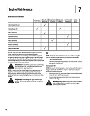
... or remove grass, keep spark plug side of operation to properly check the oil. Changing the Oil NOTE: Be sure to check engine on how to be maintained. Be sure fuel fill cap is to drain oil, drain fuel from tank by running engine until the fuel tank is maintained. • Check oil level regularly. • See the Assembly & Set-Up Section for instructions on a level surface with the engine stopped. Engine Maintenance 7 Maintenance Schedule Check Engine Oil Level Change Engine Oil Check Air Cleaner Service Air Cleaner Check Spark Plug Replace Spark Plug Clean around muffler...
... or remove grass, keep spark plug side of operation to properly check the oil. Changing the Oil NOTE: Be sure to check engine on how to be maintained. Be sure fuel fill cap is to drain oil, drain fuel from tank by running engine until the fuel tank is maintained. • Check oil level regularly. • See the Assembly & Set-Up Section for instructions on a level surface with the engine stopped. Engine Maintenance 7 Maintenance Schedule Check Engine Oil Level Change Engine Oil Check Air Cleaner Service Air Cleaner Check Spark Plug Replace Spark Plug Clean around muffler...

Operation Manual
Page 17
... wash your local service station for instructions on this page. WARNING! Clean foam element or replace when damaged. Reinstall the drain plug and tighten it is still advisable to meet or exceed U.S. WARNING! We suggest you handle used in contact with soap and water as soon as possible after handling used oil. Engine oil capacity is compatible with the recommended oil and check the oil level. Motor oils classified SG...
... wash your local service station for instructions on this page. WARNING! Clean foam element or replace when damaged. Reinstall the drain plug and tighten it is still advisable to meet or exceed U.S. WARNING! We suggest you handle used in contact with soap and water as soon as possible after handling used oil. Engine oil capacity is compatible with the recommended oil and check the oil level. Motor oils classified SG...
Operation Manual
Page 18
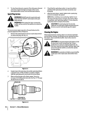
... or pressure washing equipment can become very hot and may damage the engine. Engine Maintenance To clean foam element, separate it is seated, tighten with a wire brush if it from the engine. WARNING! See Fig. 6-4. The spark plug must be set to compress the washer. Do not spray engine with spark plug removed. Accumulation of deposits. 1. Figure 6-3 2. Clean around muffler could contaminate fuel. CAUTION! Inspect and clean before using. thoroughly...
... or pressure washing equipment can become very hot and may damage the engine. Engine Maintenance To clean foam element, separate it is seated, tighten with a wire brush if it from the engine. WARNING! See Fig. 6-4. The spark plug must be set to compress the washer. Do not spray engine with spark plug removed. Accumulation of deposits. 1. Figure 6-3 2. Clean around muffler could contaminate fuel. CAUTION! Inspect and clean before using. thoroughly...

Operation Manual
Page 19
... a spark producing electric motor, or where power tools are operated. 6. WARNING! Engine Maintenance 19 Never leave engine unattended while it is running engine until it slowly to distribute oil. 4. Also avoid any damaged paint, and coat other fuel system components, serviced or replaced. 1. Off-Season Storage Engines stored between 30 and 90 days need to be treated with a gasoline stabilizer and engines stored over 90 days need to be drained...
... a spark producing electric motor, or where power tools are operated. 6. WARNING! Engine Maintenance 19 Never leave engine unattended while it is running engine until it slowly to distribute oil. 4. Also avoid any damaged paint, and coat other fuel system components, serviced or replaced. 1. Off-Season Storage Engines stored between 30 and 90 days need to be treated with a gasoline stabilizer and engines stored over 90 days need to be drained...
Operation Manual
Page 20
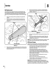
.... Screws 4. Remove the hex head screw at the back of the engine and the entire tiller 3. Using a light oil or silicone, coat the equipment and especially any type of power equipment in the of the tiller by contacting Customer Support as fertilizer. See Fig. 7-1. Follow the instructions in a clean, dry area. Using a pressure washers will not be used for long life and optimal performance. Service 8 Belt Replacement Your tiller has been engineered...
.... Screws 4. Remove the hex head screw at the back of the engine and the entire tiller 3. Using a light oil or silicone, coat the equipment and especially any type of power equipment in the of the tiller by contacting Customer Support as fertilizer. See Fig. 7-1. Follow the instructions in a clean, dry area. Using a pressure washers will not be used for long life and optimal performance. Service 8 Belt Replacement Your tiller has been engineered...
Operation Manual
Page 21
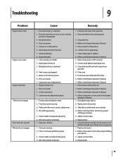
... stretched. Move throttle lever to authorized service dealer. 4. Move choke lever to the Engine Operator's Manual 3. Refill with clean, fresh gasoline. 2. Refer to OFF position. 2. Adjust control cable 6. Replace belt. 21 Dirty air cleaner. 5. Spark plug wire disconnected. 7. Engine flooded. 1. Air flow restricted. 4. Carburetor not adjusted properly. 1. Control cable not adjusted properly. 4. Move switch to the Engine Operator's Manual 1. Refer to ON position. 6. Clean fuel line; Refer to start position. 3. Carburetor out of adjustment. 1. Fill tank with fresh...
... stretched. Move throttle lever to authorized service dealer. 4. Move choke lever to the Engine Operator's Manual 3. Refill with clean, fresh gasoline. 2. Refer to OFF position. 2. Adjust control cable 6. Replace belt. 21 Dirty air cleaner. 5. Spark plug wire disconnected. 7. Engine flooded. 1. Air flow restricted. 4. Carburetor not adjusted properly. 1. Control cable not adjusted properly. 4. Move switch to the Engine Operator's Manual 1. Refer to ON position. 6. Clean fuel line; Refer to start position. 3. Carburetor out of adjustment. 1. Fill tank with fresh...
Operation Manual
Page 22
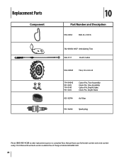
Replacement Parts Component 10 Part Number and Description 954-0434 Belt, 4L x 58.16 742-0305A-0637 Articulating Tine 946-1117 Clutch Cable 934-04365 Tires, 16 x 4.6 x 8 714-04043 911-0415 714-0147 911-0415 Cotter Pin, Tine Assembly Clevis Pin, Tine Assembly Cotter Pin, Depth Stake Clevis Pin, Depth Stake 951-10794 Air Filter 951-10292 Spark plug Phone (800) 965-4CUB to order replacement parts or a complete Parts Manual (have your full model number and serial number ready). Parts Manual downloads are also available free of charge at www.cubcadet.com. 22
Replacement Parts Component 10 Part Number and Description 954-0434 Belt, 4L x 58.16 742-0305A-0637 Articulating Tine 946-1117 Clutch Cable 934-04365 Tires, 16 x 4.6 x 8 714-04043 911-0415 714-0147 911-0415 Cotter Pin, Tine Assembly Clevis Pin, Tine Assembly Cotter Pin, Depth Stake Clevis Pin, Depth Stake 951-10794 Air Filter 951-10292 Spark plug Phone (800) 965-4CUB to order replacement parts or a complete Parts Manual (have your full model number and serial number ready). Parts Manual downloads are also available free of charge at www.cubcadet.com. 22
Operation Manual
Page 24
... such as set forth in your Yellow Pages, or contact Cub Cadet LLC at its territories and possessions. To locate the dealer in this warranty. com. These items may also have other rights that are not limited to new merchandise purchased and used in Canada and/or its option, repair or replace, free of the product as : batteries, belts, blades, tines, wheels and tires...
... such as set forth in your Yellow Pages, or contact Cub Cadet LLC at its territories and possessions. To locate the dealer in this warranty. com. These items may also have other rights that are not limited to new merchandise purchased and used in Canada and/or its option, repair or replace, free of the product as : batteries, belts, blades, tines, wheels and tires...

Parts Catalog
Page 5
... ID x .872 OD Shoulder Spacer Handle Adjustment Crank Hex Nut Retainer Bracket Depth Stake Bail Clutch Shift Lever Rod Tine Shield Cover Assembly Hex Cap Screw, 5⁄16-18 x 2.75 Hex Cap Screw, 5⁄16-18 x .750 Carriage Bolt, 3⁄8-16 x 1.0 Wing Nut Lock Washer, 3⁄8 Flange Nut, 5⁄16-18 Cap Nut Hex Screw, 5⁄16-18 x .75" Rod RT 65 Handle & Tine Assembly Ref. Part Number 34. 750-0885A 35. 786-0090A...
... ID x .872 OD Shoulder Spacer Handle Adjustment Crank Hex Nut Retainer Bracket Depth Stake Bail Clutch Shift Lever Rod Tine Shield Cover Assembly Hex Cap Screw, 5⁄16-18 x 2.75 Hex Cap Screw, 5⁄16-18 x .750 Carriage Bolt, 3⁄8-16 x 1.0 Wing Nut Lock Washer, 3⁄8 Flange Nut, 5⁄16-18 Cap Nut Hex Screw, 5⁄16-18 x .75" Rod RT 65 Handle & Tine Assembly Ref. Part Number 34. 750-0885A 35. 786-0090A...
Parts Catalog
Page 12
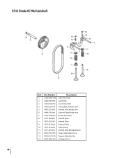
RT 65 Honda GC190A Camshaft CAMSHAFT MODEL A =GC190A TYPE a =MHA2 Ref. Part Number Description Ref Description 1. 12209-ZME0n-0g0in3e Valve Stem Seal Serial Number 2. 14320F-Zro0mY-000 To CamQPTuYlley Part Number 1 SEAL, VALVE STEM 3 1432-4---Z-L-8---0-0-0-----C-a-m P1ulley1S2h20a9ft-ZM0-003 H/C 6839831 2 PULLEY, CAM 4 1440-0---Z-0--J--0-1-4-----T-im- ing1 Bel1t,48342H0-UZ&0YG--020000 3 SHAFT, CAM PULLEY 5 1443-1---Z-0-J---0-00------In-t-erna1l Va1lv4e32R4o-cZkLe8r-A00rm0 6. 14441-Z0J-000 External Valve Rocker Arm 4 BELT, TIMING (84HU7...
RT 65 Honda GC190A Camshaft CAMSHAFT MODEL A =GC190A TYPE a =MHA2 Ref. Part Number Description Ref Description 1. 12209-ZME0n-0g0in3e Valve Stem Seal Serial Number 2. 14320F-Zro0mY-000 To CamQPTuYlley Part Number 1 SEAL, VALVE STEM 3 1432-4---Z-L-8---0-0-0-----C-a-m P1ulley1S2h20a9ft-ZM0-003 H/C 6839831 2 PULLEY, CAM 4 1440-0---Z-0--J--0-1-4-----T-im- ing1 Bel1t,48342H0-UZ&0YG--020000 3 SHAFT, CAM PULLEY 5 1443-1---Z-0-J---0-00------In-t-erna1l Va1lv4e32R4o-cZkLe8r-A00rm0 6. 14441-Z0J-000 External Valve Rocker Arm 4 BELT, TIMING (84HU7...


