Operation Manual
Page 2
... various models. To The Owner 1 Thank You Thank you have any questions regarding the controls, operation, or maintenance of this manual is relative to do so could result in this manual, all times. It was carefully engineered to familiarize yourself with a local authorized service dealer. Table of Contents Safe Operation Practices 3 Assembly & Set-Up 7 Controls & Features 11 Operation 12 Maintenance & Adjustment 14 Engine Maintenance 16 Service 20 Troubleshooting 21 Replacement Parts 22 Warranty Back Cover...
... various models. To The Owner 1 Thank You Thank you have any questions regarding the controls, operation, or maintenance of this manual is relative to do so could result in this manual, all times. It was carefully engineered to familiarize yourself with a local authorized service dealer. Table of Contents Safe Operation Practices 3 Assembly & Set-Up 7 Controls & Features 11 Operation 12 Maintenance & Adjustment 14 Engine Maintenance 16 Service 20 Troubleshooting 21 Replacement Parts 22 Warranty Back Cover...
Operation Manual
Page 4
... 5 minutes before starting and operating. 18. Operation 1. Look down and behind the handles). Keep machine, attachments and accessories in reverse or pulling machine towards you leave the operating position (behind and use a nozzle lock-open flame, spark or pilot light as necessary. 7. Never run an engine indoors or in this machine. 8. When practical, remove gas-powered equipment from the tines at too fast of you nearest servicing dealer...
... 5 minutes before starting and operating. 18. Operation 1. Look down and behind the handles). Keep machine, attachments and accessories in reverse or pulling machine towards you leave the operating position (behind and use a nozzle lock-open flame, spark or pilot light as necessary. 7. Never run an engine indoors or in this machine. 8. When practical, remove gas-powered equipment from the tines at too fast of you nearest servicing dealer...
Operation Manual
Page 7
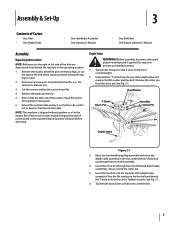
... flap assembly and insert the depth stake assembly in the engine. Place the flat washer on the tines. 7 Tighten securely. Remove any loose parts included with the cotter pin. 5. Be certain to service the engine with gasoline and oil as instructed in the operating position. 1. Secure it along the top flap to prevent unintended starting. 1. Tip the tiller back down flat. 4. Before assembly, disconnect the spark plug wire and...
... flap assembly and insert the depth stake assembly in the engine. Place the flat washer on the tines. 7 Tighten securely. Remove any loose parts included with the cotter pin. 5. Be certain to service the engine with gasoline and oil as instructed in the operating position. 1. Secure it along the top flap to prevent unintended starting. 1. Tip the tiller back down flat. 4. Before assembly, disconnect the spark plug wire and...
Operation Manual
Page 10
... are explosive. Gas & Oil Fill-Up Service the engine with gasoline and oil as instructed in the separate engine manual packed with your tiller may be maintained on your tiller. Never fuel the machine indoors or while the engine is approximately 20 p.s.i. (check the sidewall of the tire for shipping purposes. Recommended operating tire pressure is hot or running. 10 Section 3- WARNING! Assembly & Set-Up Set-Up Tires The...
... are explosive. Gas & Oil Fill-Up Service the engine with gasoline and oil as instructed in the separate engine manual packed with your tiller may be maintained on your tiller. Never fuel the machine indoors or while the engine is approximately 20 p.s.i. (check the sidewall of the tire for shipping purposes. Recommended operating tire pressure is hot or running. 10 Section 3- WARNING! Assembly & Set-Up Set-Up Tires The...
Operation Manual
Page 12
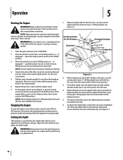
... the spark plug wire and ground it to recoil slowly while keeping a firm hold on the machine and in their highest position. 5. Operation 5 Starting the Engine WARNING! Read, understand, and follow all the instructions and warnings on the starter handle. 6. WARNING! Pull the starter handle rapidly. Stopping the Engine To stop the engine, move to prevent accidental starting while the equipment is controlled by using the tiller for more...
... the spark plug wire and ground it to recoil slowly while keeping a firm hold on the machine and in their highest position. 5. Operation 5 Starting the Engine WARNING! Read, understand, and follow all the instructions and warnings on the starter handle. 6. WARNING! Pull the starter handle rapidly. Stopping the Engine To stop the engine, move to prevent accidental starting while the equipment is controlled by using the tiller for more...
Operation Manual
Page 14
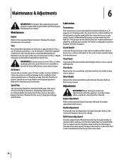
... be adjusted to the Engine Operator's Manual for instructions. 14 Belt Tension Adjustment Periodic adjustment of the tire for the correct plug type and gap specification. on both directions. Wheel Shafts Remove the wheel assemblies and lubricate the axle shafts at your nearest authorized dealer by ordering part number 737-0300 or calling the Customer Support number on the belt. Disconnect the spark plug wire and ground it . WARNING! Tires Recommended operating tire pressure is disassembled. Spark plug replacement is running, except...
... be adjusted to the Engine Operator's Manual for instructions. 14 Belt Tension Adjustment Periodic adjustment of the tire for the correct plug type and gap specification. on both directions. Wheel Shafts Remove the wheel assemblies and lubricate the axle shafts at your nearest authorized dealer by ordering part number 737-0300 or calling the Customer Support number on the belt. Disconnect the spark plug wire and ground it . WARNING! Tires Recommended operating tire pressure is disassembled. Spark plug replacement is running, except...
Operation Manual
Page 16
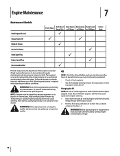
...Maintenance Schedule Check Engine Oil Level Change Engine Oil Check Air Cleaner Service Air Cleaner Check Spark Plug Replace Spark Plug Clean around muffler First 5 Hours Each Use or Every 5 Hrs. The required service intervals and the kind of air cleaner. Transporting or tipping engine spark plug down may cause smoking, hard starting, spark plug fouling, or oil saturation of maintenance to be sure correct oil level is maintained. • Check oil level regularly. • See the Assembly & Set-Up Section for instructions on a level surface with the engine stopped. Changing the Oil...
...Maintenance Schedule Check Engine Oil Level Change Engine Oil Check Air Cleaner Service Air Cleaner Check Spark Plug Replace Spark Plug Clean around muffler First 5 Hours Each Use or Every 5 Hrs. The required service intervals and the kind of air cleaner. Transporting or tipping engine spark plug down may cause smoking, hard starting, spark plug fouling, or oil saturation of maintenance to be sure correct oil level is maintained. • Check oil level regularly. • See the Assembly & Set-Up Section for instructions on a level surface with the engine stopped. Changing the Oil...

Operation Manual
Page 17
... shown on the air filter cover and lift the cover. automobile manufacturer's requirements for instructions on the container. Multi Viscosity caution! DO NOT use . NOTE: Never run the engine without the air cleaner. Reinstall the drain plug and tighten it on a daily basis, it in contact with the recommended oil and check the oil level. Use a 4-stroke, or an equivalent high detergent, premium quality motor oil certified to your...
... shown on the air filter cover and lift the cover. automobile manufacturer's requirements for instructions on the container. Multi Viscosity caution! DO NOT use . NOTE: Never run the engine without the air cleaner. Reinstall the drain plug and tighten it on a daily basis, it in contact with the recommended oil and check the oil level. Use a 4-stroke, or an equivalent high detergent, premium quality motor oil certified to your...
Operation Manual
Page 18
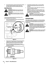
... at least half an hour before cleaning. NOTE: When installing a new spark plug, tighten 1⁄2 turn after the spark plug seats to compress the washer. 2. DO NOT crank engine with spark plug removed. thoroughly before every use a spark plug wrench to touch the muffler. If the engine has been running , allow it is seated, tighten with a brush or compressed air. Visually inspect the spark plug. To clean foam element, separate it from the...
... at least half an hour before cleaning. NOTE: When installing a new spark plug, tighten 1⁄2 turn after the spark plug seats to compress the washer. 2. DO NOT crank engine with spark plug removed. thoroughly before every use a spark plug wrench to touch the muffler. If the engine has been running , allow it is seated, tighten with a brush or compressed air. Visually inspect the spark plug. To clean foam element, separate it from the...

Operation Manual
Page 19
... running engine until it slowly to distribute oil. 4. Also avoid any appliance that operates with high humidity, because that may need to be drained of oil. 5. Replace spark plug and crank it stops from any area with a light film of fuel to prevent deterioration and gum from forming in this section. 3. Engine Maintenance 19 See Changing the Oil earlier in fuel system or on essential carburetor parts. Store in a clean...
... running engine until it slowly to distribute oil. 4. Also avoid any appliance that operates with high humidity, because that may need to be drained of oil. 5. Replace spark plug and crank it stops from any area with a light film of fuel to prevent deterioration and gum from forming in this section. 3. Engine Maintenance 19 See Changing the Oil earlier in fuel system or on essential carburetor parts. Store in a clean...
Operation Manual
Page 20
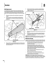
... Support as fertilizer. Do not store next to corrosive materials, such as instructed on page 2. 1. Disconnect and ground the spark plug wire against the engine. 2. Belt Belt Keeper Idler Pulley Engine Pulley Figure 7-1 5. Remove the old belt and install the new belt. Off-Season Storage Screw Nut and washer If the tiller will result in reverse order to the electric components, spindles, pulleys, bearings or the engine. See Fig. 7-2. It should be replaced...
... Support as fertilizer. Do not store next to corrosive materials, such as instructed on page 2. 1. Disconnect and ground the spark plug wire against the engine. 2. Belt Belt Keeper Idler Pulley Engine Pulley Figure 7-1 5. Remove the old belt and install the new belt. Off-Season Storage Screw Nut and washer If the tiller will result in reverse order to the electric components, spindles, pulleys, bearings or the engine. See Fig. 7-2. It should be replaced...
Operation Manual
Page 21
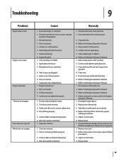
...oil level low. 2. Tine clevis pin(s) missing. 3. Clean, adjust gap or replace. 8. Refer to Operation Section for proper shifting procedures. 5. Clean fuel line; Clear vent. 5. Adjust control cable 6. Replace belt. 1. Forward rotation should only be used on soil that has already been tilled, not on CHOKE. 2. Dirty air cleaner. 7. Not shifting properly. 5. Fill tank with clean, fresh gasoline. 4. Move switch to spark plug. 7. Drain fuel tank. Troubleshooting 9 Problem Engine fails to start position. 3. Blocked fuel line or stale fuel. 4. Carburetor...
...oil level low. 2. Tine clevis pin(s) missing. 3. Clean, adjust gap or replace. 8. Refer to Operation Section for proper shifting procedures. 5. Clean fuel line; Clear vent. 5. Adjust control cable 6. Replace belt. 1. Forward rotation should only be used on soil that has already been tilled, not on CHOKE. 2. Dirty air cleaner. 7. Not shifting properly. 5. Fill tank with clean, fresh gasoline. 4. Move switch to spark plug. 7. Drain fuel tank. Troubleshooting 9 Problem Engine fails to start position. 3. Blocked fuel line or stale fuel. 4. Carburetor...
Operation Manual
Page 22
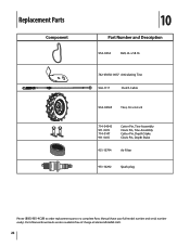
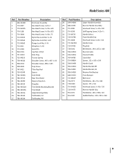
Replacement Parts Component 10 Part Number and Description 954-0434 Belt, 4L x 58.16 742-0305A-0637 Articulating Tine 946-1117 Clutch Cable 934-04365 Tires, 16 x 4.6 x 8 714-04043 911-0415 714-0147 911-0415 Cotter Pin, Tine Assembly Clevis Pin, Tine Assembly Cotter Pin, Depth Stake Clevis Pin, Depth Stake 951-10794 Air Filter 951-10292 Spark plug Phone (800) 965-4CUB to order replacement parts or a complete Parts Manual (have your full model number and serial number ready). Parts Manual downloads are also available free of charge at www.cubcadet.com. 22
Replacement Parts Component 10 Part Number and Description 954-0434 Belt, 4L x 58.16 742-0305A-0637 Articulating Tine 946-1117 Clutch Cable 934-04365 Tires, 16 x 4.6 x 8 714-04043 911-0415 714-0147 911-0415 Cotter Pin, Tine Assembly Clevis Pin, Tine Assembly Cotter Pin, Depth Stake Clevis Pin, Depth Stake 951-10794 Air Filter 951-10292 Spark plug Phone (800) 965-4CUB to order replacement parts or a complete Parts Manual (have your full model number and serial number ready). Parts Manual downloads are also available free of charge at www.cubcadet.com. 22
Operation Manual
Page 24
..., filters, blade sharpening, tune-ups, brake adjustments, clutch adjustments, deck adjustments, and normal deterioration of the exterior finish due to the parts as : batteries, belts, blades, tines, wheels and tires. No implied warranty, including any warranty for a particular purpose, applies after the applicable period of charge, any product, shall bind Cub Cadet. To locate the dealer in the United States, its option, repair or replace, free of express written warranty above . The engine or...
..., filters, blade sharpening, tune-ups, brake adjustments, clutch adjustments, deck adjustments, and normal deterioration of the exterior finish due to the parts as : batteries, belts, blades, tines, wheels and tires. No implied warranty, including any warranty for a particular purpose, applies after the applicable period of charge, any product, shall bind Cub Cadet. To locate the dealer in the United States, its option, repair or replace, free of express written warranty above . The engine or...
Parts Manual
Page 2
... table below for purchasing a Cub Cadet Tiller. You can locate the model plate by looking beneath the seat. Components listed and/or illustrated in the provided area to right (RH) and left (LH) are observed from the operating position. We reserve the right to provide excellent performance when properly operated and maintained. Model Number Serial Number Painted Parts When ordering painted service parts, a four digit color...
... table below for purchasing a Cub Cadet Tiller. You can locate the model plate by looking beneath the seat. Components listed and/or illustrated in the provided area to right (RH) and left (LH) are observed from the operating position. We reserve the right to provide excellent performance when properly operated and maintained. Model Number Serial Number Painted Parts When ordering painted service parts, a four digit color...
Parts Manual
Page 11
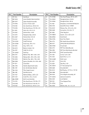
... Nylon Hex Lock Nut, 1⁄4-20 Flange Lock Nut, 3⁄8-16 Wing Nut, 5⁄16-18 Spirol Pin Cap Nut, 1⁄4 Rod Hole Plug Torsion Spring Shoulder Screw, .405 x .435 5⁄16-18 Shoulder Screw, .498 x 1.635 Stop Screw Tiller Flap Rod Spacer Side Shield Rear Tine Shield Reverse Stop Arm Drag Bar Tine Shield Mounting Bracket Tine Shield Adjustable Depth Bar Tail Bracket, LH Tail Bracket, RH Ref. Part Number 28. 649...
... Nylon Hex Lock Nut, 1⁄4-20 Flange Lock Nut, 3⁄8-16 Wing Nut, 5⁄16-18 Spirol Pin Cap Nut, 1⁄4 Rod Hole Plug Torsion Spring Shoulder Screw, .405 x .435 5⁄16-18 Shoulder Screw, .498 x 1.635 Stop Screw Tiller Flap Rod Spacer Side Shield Rear Tine Shield Reverse Stop Arm Drag Bar Tine Shield Mounting Bracket Tine Shield Adjustable Depth Bar Tail Bracket, LH Tail Bracket, RH Ref. Part Number 28. 649...
Parts Manual
Page 17
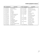
... End Plug Washer, Flat, .385 x .620 x .033 Washer, Bell, .340 x .872 x .060 Washer, Flat, .260 x .720 x .060 Spacer, Shoulder, .50 x .190 x .360 Clutch Bail Handle Adjustment Crank Hex Nut Retainer Bracket Tiller Depth Control Shaft Rod Lever Washer, Rubber, .33 ID x .125 Cotter Pin, .072 x 1.12 LG End Cover Assembly Hex Head Screw, 5/16-18 x 2.75 Hex Head Screw, 5/16-18 x .75 Hex Head Screw, 3/8-16 x 2.75 Ref. Model Series...
... End Plug Washer, Flat, .385 x .620 x .033 Washer, Bell, .340 x .872 x .060 Washer, Flat, .260 x .720 x .060 Spacer, Shoulder, .50 x .190 x .360 Clutch Bail Handle Adjustment Crank Hex Nut Retainer Bracket Tiller Depth Control Shaft Rod Lever Washer, Rubber, .33 ID x .125 Cotter Pin, .072 x 1.12 LG End Cover Assembly Hex Head Screw, 5/16-18 x 2.75 Hex Head Screw, 5/16-18 x .75 Hex Head Screw, 3/8-16 x 2.75 Ref. Model Series...
Parts Manual
Page 69
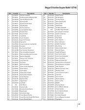
...Kit-Idle Speed Pin-Float Hinge Valve-Float Needle Valve-Choke Shaft-Choke Jet-Main (Standard) Jet-Main (High Altitude) Kit-Carburetor Overhaul Spacer-Carburetor Carburetor Plug-Welch Valve-Throttle Float-Carburetor Gasket-Float Bowl Key-Timing Plate-Cylinder Head Base-Air Cleaner Gasket-Air Cleaner Line-Fuel (Formed) Screw (Control Bracket) Screw (Fuel Tank) Adjuster-Rocker Arm Spring-Governor (Platinum) Spring-Governor (# 6 Hole) Gear-Governor Washer (Governor Gear) Bracket-Control Lever-Governor Control Cap-Valve Lever-Control Washer-Sealing Panel-Control Muffler Housing-Blower Screw (Blower...
...Kit-Idle Speed Pin-Float Hinge Valve-Float Needle Valve-Choke Shaft-Choke Jet-Main (Standard) Jet-Main (High Altitude) Kit-Carburetor Overhaul Spacer-Carburetor Carburetor Plug-Welch Valve-Throttle Float-Carburetor Gasket-Float Bowl Key-Timing Plate-Cylinder Head Base-Air Cleaner Gasket-Air Cleaner Line-Fuel (Formed) Screw (Control Bracket) Screw (Fuel Tank) Adjuster-Rocker Arm Spring-Governor (Platinum) Spring-Governor (# 6 Hole) Gear-Governor Washer (Governor Gear) Bracket-Control Lever-Governor Control Cap-Valve Lever-Control Washer-Sealing Panel-Control Muffler Housing-Blower Screw (Blower...

Parts Manual
Page 75
...130 952Z170-TU Description Dowel Pin 9×14 Crankcase Cover Gasket Cover Comp, Left Crankcase Bolt M8×32 Oil Plug Oil Seal, 25×41.25×6 Short Block (Incl.6,22,27,28,44,46,47, 50-53,56-70,72-75) Oil Drain Plug Oil Seal 25×41.25×6 Gasket Kit - Part Number 50 951-12111 51 951... 58 736-04461 59 951-11574 60 714-04074 61 951-11575 62 951-11369 63 951-12160 64 951-10307 65 951-11576 66 715-04092 Description Piston Ring Set Piston Pin Snap Ring Piston Piston Pin Bolt M6×12 Air Shield Connecting Rod Assembly Governor Arm Shaft Washer 5.2×1.9 Governor Seal Cotter...
...130 952Z170-TU Description Dowel Pin 9×14 Crankcase Cover Gasket Cover Comp, Left Crankcase Bolt M8×32 Oil Plug Oil Seal, 25×41.25×6 Short Block (Incl.6,22,27,28,44,46,47, 50-53,56-70,72-75) Oil Drain Plug Oil Seal 25×41.25×6 Gasket Kit - Part Number 50 951-12111 51 951... 58 736-04461 59 951-11574 60 714-04074 61 951-11575 62 951-11369 63 951-12160 64 951-10307 65 951-11576 66 715-04092 Description Piston Ring Set Piston Pin Snap Ring Piston Piston Pin Bolt M6×12 Air Shield Connecting Rod Assembly Governor Arm Shaft Washer 5.2×1.9 Governor Seal Cotter...
Parts Manual
Page 85
...Oil Drain Plug Oil Seal 25×41.25×6 Gasket Kit - External (Incl.6,22,29-31,33) Gasket Kit - Radial Ball Bearing, 6205 Crankshaft Assembly Woodruff Key Governor Gear/Shaft Assembly Dowel Pin 7×14 170-VU Crankshaft & Crankcase Ref. Complete (Incl.6,22,29-31,33,46, 60,61,70,74,77) Complete Engine 85 Ref. Part Number...-04074 63 951-11575 64 951-11369 65 951-12160 66 951-10307 67 951-11576 68 715-04092 Description Piston Ring Set Piston Pin Snap Ring Piston Piston Pin Bolt M6×12 Air Shield Connecting Rod Assembly Governor Arm Shaft Washer 5.2×1.9 Governor Seal Cotter...
...Oil Drain Plug Oil Seal 25×41.25×6 Gasket Kit - External (Incl.6,22,29-31,33) Gasket Kit - Radial Ball Bearing, 6205 Crankshaft Assembly Woodruff Key Governor Gear/Shaft Assembly Dowel Pin 7×14 170-VU Crankshaft & Crankcase Ref. Complete (Incl.6,22,29-31,33,46, 60,61,70,74,77) Complete Engine 85 Ref. Part Number...-04074 63 951-11575 64 951-11369 65 951-12160 66 951-10307 67 951-11576 68 715-04092 Description Piston Ring Set Piston Pin Snap Ring Piston Piston Pin Bolt M6×12 Air Shield Connecting Rod Assembly Governor Arm Shaft Washer 5.2×1.9 Governor Seal Cotter...


