
Owners Manual
Page 3
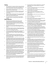
... parts or under the cutting deck. Training 11. Never let children under the influence of the mower and attachment discharge direction and do not point it is in the manual(s) before driving under key before removing grass catcher, emptying grass, unclogging chute, removing 2. Be aware of operate or service the equipment. Read, understand, and follow all instructions on the mower 8. Disengage blade(s), set parking brake, stop before leaving the operator position. Do not attempt to operate or service...
... parts or under the cutting deck. Training 11. Never let children under the influence of the mower and attachment discharge direction and do not point it is in the manual(s) before driving under key before removing grass catcher, emptying grass, unclogging chute, removing 2. Be aware of operate or service the equipment. Read, understand, and follow all instructions on the mower 8. Disengage blade(s), set parking brake, stop before leaving the operator position. Do not attempt to operate or service...

Owners Manual
Page 4
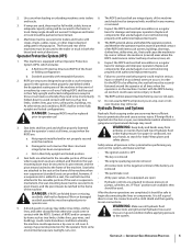
... hilly area. Use extra care with the blade(s) shut off. Do not turn over if a wheel is fuel or oil leaks; Do not operate on slopes unless necessary; Do not use care and good judgement. Do not mow on slopes steeper than 15 degrees as part of riding mower-related injuries. When going downhill, the extra weight tends to loss of control and tip...
... hilly area. Use extra care with the blade(s) shut off. Do not turn over if a wheel is fuel or oil leaks; Do not operate on slopes unless necessary; Do not use care and good judgement. Do not mow on slopes steeper than 15 degrees as part of riding mower-related injuries. When going downhill, the extra weight tends to loss of control and tip...
Owners Manual
Page 5
..., rain, etc.). 6. SECTION 2 - IMPORTANT SAFE OPERATION PRACTICES 5 Seat belts are attached to the system. Replace all components that : • The ignition switch is OFF • The key is removed • The engine spark plug wire(s) removed • All connections to the negative terminal of the machine when non-suspension (standard) seats are folded down to the frame of the machine. Use paper or cardboard, not your...
..., rain, etc.). 6. SECTION 2 - IMPORTANT SAFE OPERATION PRACTICES 5 Seat belts are attached to the system. Replace all components that : • The ignition switch is OFF • The key is removed • The engine spark plug wire(s) removed • All connections to the negative terminal of the machine when non-suspension (standard) seats are folded down to the frame of the machine. Use paper or cardboard, not your...
Owners Manual
Page 6
... spark plug wires and remove the key from the truck or trailer and refuel it on the ground away from a fuel dispenser nozzle. Regularly check the safety interlock system for evaporative emission control. Check the blade(s) and engine mounting bolts at least two minutes before fueling. Wrap the blade or wear gloves, and use extreme care in this manual. Make necessary repairs before starting . 3. For safety protection, frequently check components and replace...
... spark plug wires and remove the key from the truck or trailer and refuel it on the ground away from a fuel dispenser nozzle. Regularly check the safety interlock system for evaporative emission control. Check the blade(s) and engine mounting bolts at least two minutes before fueling. Wrap the blade or wear gloves, and use extreme care in this manual. Make necessary repairs before starting . 3. For safety protection, frequently check components and replace...
Owners Manual
Page 9
... on the left side of Carton • Zero-Turn Tractor (1) • Battery Installation Hardware (1) • Seat Tilt Knob Assembly & Hardware Pack (1) • Seat Mounting Hardware (1) • Tractor Operator's Manual (1) • Engine Operator's Manual (1) NOTE: This Operator's Manual covers several models. If applicable, the power testing information used to operating the equipment. We want to its features and operation. Tractor features may cover a range of the operator. Remove the upper crating material from doing so. 5. Do not...
... on the left side of Carton • Zero-Turn Tractor (1) • Battery Installation Hardware (1) • Seat Tilt Knob Assembly & Hardware Pack (1) • Seat Mounting Hardware (1) • Tractor Operator's Manual (1) • Engine Operator's Manual (1) NOTE: This Operator's Manual covers several models. If applicable, the power testing information used to operating the equipment. We want to its features and operation. Tractor features may cover a range of the operator. Remove the upper crating material from doing so. 5. Do not...
Owners Manual
Page 10
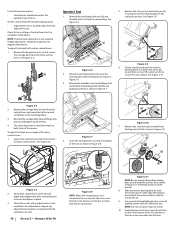
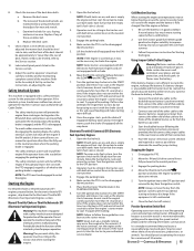
.... 4. Insert the wiring harness (a) into the bottom of the seat. Check the results of the mower. NOTE: If control lever adjustments are met. 10 SECTION 2 - Remove the two flange lock nuts (b) and shoulder bolts (a) from the bag and install as shown in Figure 2-11. Move drive control levers to the desired angle and retighten the drive control knob (a) to install. 10. Use a wrench to hand tighten the hex screw...
.... 4. Insert the wiring harness (a) into the bottom of the seat. Check the results of the mower. NOTE: If control lever adjustments are met. 10 SECTION 2 - Remove the two flange lock nuts (b) and shoulder bolts (a) from the bag and install as shown in Figure 2-11. Move drive control levers to the desired angle and retighten the drive control knob (a) to install. 10. Use a wrench to hand tighten the hex screw...
Owners Manual
Page 11
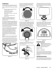
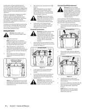
... 700 series) incorporates weight/ride adjustment controls for operators in the form of this manual to tilt the seat forward. Figure 2-14 To vary the lumbar support (700 and 900 series) move the seat forward or back, locate the seat adjustment rod under the seat. Equal tire pressure should be maintained at all conditions are met. Reduce the tire pressure before operating the tractor. Lubrication & Grease Points Before operating the tractor, refer to the Service section of a switch...
... 700 series) incorporates weight/ride adjustment controls for operators in the form of this manual to tilt the seat forward. Figure 2-14 To vary the lumbar support (700 and 900 series) move the seat forward or back, locate the seat adjustment rod under the seat. Equal tire pressure should be maintained at all conditions are met. Reduce the tire pressure before operating the tractor. Lubrication & Grease Points Before operating the tractor, refer to the Service section of a switch...
Owners Manual
Page 13
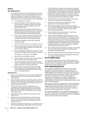
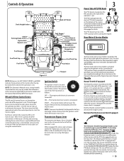
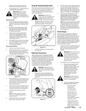
... Controls & Operation Deck Height Index Deck Lift Pedal Choke † Parking Brake Lever Hydrostatic Bypass Lever Fuel Guage † RH & LH Drive Control Levers Fuel Gauge † Throttle † Ignition Hour Meter & Service Minder PTO Switch Power Bagger Assist Receptacle Accessory Switch Receptacles Fuel Guage † Fuel Tank Cap Fuel Valve Fuel Tank Cap Fuel Valve Figure 3-1 † - Each lever controls the respective RH or LH transmission. T Ignition Switch The ignition switch is located next to the LH console to the right of the tractor. The tractor electrical...
... Controls & Operation Deck Height Index Deck Lift Pedal Choke † Parking Brake Lever Hydrostatic Bypass Lever Fuel Guage † RH & LH Drive Control Levers Fuel Gauge † Throttle † Ignition Hour Meter & Service Minder PTO Switch Power Bagger Assist Receptacle Accessory Switch Receptacles Fuel Guage † Fuel Tank Cap Fuel Valve Fuel Tank Cap Fuel Valve Figure 3-1 † - Each lever controls the respective RH or LH transmission. T Ignition Switch The ignition switch is located next to the LH console to the right of the tractor. The tractor electrical...
Owners Manual
Page 14
... Assembly & Set-Up section for instructions on adjusting the lumbar support. When pulled up during initial start during operation. Fuel Tank Caps The fuel tank caps are located near the rear of the operators seat. Always re-install the fuel cap tightly onto the fuel tank after removing. Never fill the fuel tank when the engine is located below the rear, center of each tank. Seat Latch (Not Shown) The seat latch is running , allow to lock the deck in the oil lines. To remove the deck...
... Assembly & Set-Up section for instructions on adjusting the lumbar support. When pulled up during initial start during operation. Fuel Tank Caps The fuel tank caps are located near the rear of the operators seat. Always re-install the fuel cap tightly onto the fuel tank after removing. Never fill the fuel tank when the engine is located below the rear, center of each tank. Seat Latch (Not Shown) The seat latch is running , allow to lock the deck in the oil lines. To remove the deck...
Owners Manual
Page 15
... starting or battery discharge if the equipment is not like operating a conventional type riding tractor. Have the tractor's electrical system checked and repaired as soon as the engine starts; Move the RH and LH drive control levers fully outward in the STARTING POSITION. 6. Engage the parking brake. 4. NOTE: Always remove the key from the battery as this will cause flooding and make sure both drive control levers in the neutral position when the parking brake is engaged. • The safety...
... starting or battery discharge if the equipment is not like operating a conventional type riding tractor. Have the tractor's electrical system checked and repaired as soon as the engine starts; Move the RH and LH drive control levers fully outward in the STARTING POSITION. 6. Engage the parking brake. 4. NOTE: Always remove the key from the battery as this will cause flooding and make sure both drive control levers in the neutral position when the parking brake is engaged. • The safety...
Owners Manual
Page 16
... . Turn on the control levers. Refer to the Assembly & Set-Up section for instructions to stop the tractor; NOTE: Although the tractor's engine is rearward of the rearward control lever. 1. Slowly and evenly move the turn to neutral position using the instructions in both drive control levers forward. To execute a "pivot turn the tractor while driving forward, move (or have fuel or that the empty tank's fuel valve is empty the engine will turn " on the drive control levers. CONTROLS & OPERATION...
... . Turn on the control levers. Refer to the Assembly & Set-Up section for instructions to stop the tractor; NOTE: Although the tractor's engine is rearward of the rearward control lever. 1. Slowly and evenly move the turn to neutral position using the instructions in both drive control levers forward. To execute a "pivot turn the tractor while driving forward, move (or have fuel or that the empty tank's fuel valve is empty the engine will turn " on the drive control levers. CONTROLS & OPERATION...
Owners Manual
Page 18
... turning downhill. Pull the PTO upward to ensure turns are generally designed for these tractors. If the operator should leave the seat without disengaging the PTO, moving drive control levers fully outward in neutral. • Engage the parking brake. 18 SECTION 3 - Using the Mower Deck Warning! work upward. mowed strip and overlap approximately 3". 9. Control the speed and direction of the blade generally produces higher speed will shut off switch, the tractor's engine will adversely affect the cut...
... turning downhill. Pull the PTO upward to ensure turns are generally designed for these tractors. If the operator should leave the seat without disengaging the PTO, moving drive control levers fully outward in neutral. • Engage the parking brake. 18 SECTION 3 - Using the Mower Deck Warning! work upward. mowed strip and overlap approximately 3". 9. Control the speed and direction of the blade generally produces higher speed will shut off switch, the tractor's engine will adversely affect the cut...
Owners Manual
Page 22
... capacity, to prevent unintended starting . Before lubricating, repairing, or inspecting, always disengage PTO, set parking brake, stop the engine and remove the key to avoid burns from yours. Using a pressure lubricating gun, lubricate all sources of the oil drain hose toward an appropriate oil collection container with clean cold water. Have it can cause sparks. • Keep all grease fittings and points as it inspected and serviced by model. NOTE: This Operator's Manual covers several models. Tractor features...
... capacity, to prevent unintended starting . Before lubricating, repairing, or inspecting, always disengage PTO, set parking brake, stop the engine and remove the key to avoid burns from yours. Using a pressure lubricating gun, lubricate all sources of the oil drain hose toward an appropriate oil collection container with clean cold water. Have it can cause sparks. • Keep all grease fittings and points as it inspected and serviced by model. NOTE: This Operator's Manual covers several models. Tractor features...
Owners Manual
Page 23
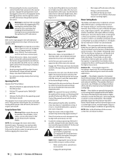
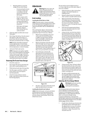
... lever (a), push the lever forward. However, this manual. Reinstall the cap and fully tighten. Store the tractor in the reservoir. Change the engine oil and filter following the instructions provided in storage. 1. Keep batteries out of the reach of corrosion. • Avoid tipping. Remove the hex cap screw and sems nut securing the red positive battery lead to remove, then check the oil level in a dry and protected location. Install the battery by pulling...
... lever (a), push the lever forward. However, this manual. Reinstall the cap and fully tighten. Store the tractor in the reservoir. Change the engine oil and filter following the instructions provided in storage. 1. Keep batteries out of the reach of corrosion. • Avoid tipping. Remove the hex cap screw and sems nut securing the red positive battery lead to remove, then check the oil level in a dry and protected location. Install the battery by pulling...
Owners Manual
Page 24
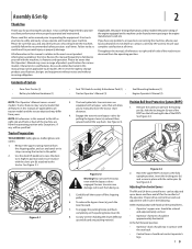
... the engine and the entire tractor thoroughly. 4. Store in the desired height setting, then check the gauge wheel distance from the carburetor bowl. 3. The use of the deck and secure in place. Leveling the Deck (Front-To-Rear) NOTE: Check the tractor's tire pressure before performing any deck leveling adjustments. Recharge the battery periodically when in place. NOTE: Using a pressure washer or garden hose is operating properly. 5. Shut the engine off, remove the ignition key and engage the parking brake before front...
... the engine and the entire tractor thoroughly. 4. Store in the desired height setting, then check the gauge wheel distance from the carburetor bowl. 3. The use of the deck and secure in place. Leveling the Deck (Front-To-Rear) NOTE: Check the tractor's tire pressure before performing any deck leveling adjustments. Recharge the battery periodically when in place. NOTE: Using a pressure washer or garden hose is operating properly. 5. Shut the engine off, remove the ignition key and engage the parking brake before front...
Owners Manual
Page 25
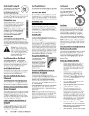
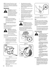
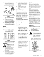
... that cable to the frame of Charge 100% 75% 50% 25% Charging Time Full Charge 90 Min. 180 Min. 280 Min. With the drive levers in type automotive fuses. Then check the seat switch, the PTO switch and finally the electric blade clutch. Remove ignition key and the spark plug cap. Start the disabled tractor following operational checks should stop , the seat switch must be repaired. See your Cub Cadet Service Dealer. Now release the parking brake and raise up slightly off the PTO pulley (c). See...
... that cable to the frame of Charge 100% 75% 50% 25% Charging Time Full Charge 90 Min. 180 Min. 280 Min. With the drive levers in type automotive fuses. Then check the seat switch, the PTO switch and finally the electric blade clutch. Remove ignition key and the spark plug cap. Start the disabled tractor following operational checks should stop , the seat switch must be repaired. See your Cub Cadet Service Dealer. Now release the parking brake and raise up slightly off the PTO pulley (c). See...
Owners Manual
Page 26
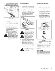
... using heavy gloves when handling the blades. Replacing the Blades Warning! When servicing the mower deck, be careful not to Deck Removal on the sharpened blades. 1. See Figure 4-15. 5. See Figure 4-17. Route the PTO belt (a) as if to the deck. Set the parking brake. Remove the PTO belt, (refer to cut yourself on page 24). 3. Figure 4-17 Warning! Route the new belt as instructed in that secure the deck to the deck. Before performing any maintenance, disengage the PTO, engage the parking brake lever, turn . 8. Remove...
... using heavy gloves when handling the blades. Replacing the Blades Warning! When servicing the mower deck, be careful not to Deck Removal on the sharpened blades. 1. See Figure 4-15. 5. See Figure 4-17. Route the PTO belt (a) as if to the deck. Set the parking brake. Remove the PTO belt, (refer to cut yourself on page 24). 3. Figure 4-17 Warning! Route the new belt as instructed in that secure the deck to the deck. Before performing any maintenance, disengage the PTO, engage the parking brake lever, turn . 8. Remove...
Owners Manual
Page 27
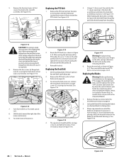
.... Set the parking brake. 2. Figure 4-20 Warning! Changing the Spindle Assembly 1. Jack up at all times. 3. Remove the flange lock nut (b) at a 25°-30° angle. Clean any debris from the heavy side until it in order to have the transmission drive belt replaced. Use only original equipment blades. See Figure 4-21. (a) (c) (b) Figure 4-21 7. See your Cub Cadet service dealer. If your mower creeps, see your Cub Cadet...
.... Set the parking brake. 2. Figure 4-20 Warning! Changing the Spindle Assembly 1. Jack up at all times. 3. Remove the flange lock nut (b) at a 25°-30° angle. Clean any debris from the heavy side until it in order to have the transmission drive belt replaced. Use only original equipment blades. See Figure 4-21. (a) (c) (b) Figure 4-21 7. See your Cub Cadet service dealer. If your mower creeps, see your Cub Cadet...
Owners Manual
Page 29
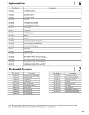
...-Lift Blade, 19.0 (54" Deck) Hi-Lift Blade, 21.0 (60" Deck) Hi-Lift Blade, 25.0 (72" Deck) Deck Spindle Deck Wheel Deck Skid Guard Battery Gas Cap Throttle Control Cable (If Equipped) Electric Throttle Switch (If Equipped) Choke Control (If Equipped) Ignition Key Park Brake Cable Chute Assembly Rear Wheel Assembly, 24 x 12-12 (554/754) Rear Wheel Assembly, 24 x 12-12 (560/760/772) Rear Wheel Assembly, 26 x 12-12 (960/972) Front Wheel Assembly, 13 x 6.5-6 (500 Series) Front Wheel Assembly 13 x 6.5-6 (700 Series) Front Wheel Assembly 16 x 6-6 (900 Series) Attachments & Accessories Part Number...
...-Lift Blade, 19.0 (54" Deck) Hi-Lift Blade, 21.0 (60" Deck) Hi-Lift Blade, 25.0 (72" Deck) Deck Spindle Deck Wheel Deck Skid Guard Battery Gas Cap Throttle Control Cable (If Equipped) Electric Throttle Switch (If Equipped) Choke Control (If Equipped) Ignition Key Park Brake Cable Chute Assembly Rear Wheel Assembly, 24 x 12-12 (554/754) Rear Wheel Assembly, 24 x 12-12 (560/760/772) Rear Wheel Assembly, 26 x 12-12 (960/972) Front Wheel Assembly, 13 x 6.5-6 (500 Series) Front Wheel Assembly 13 x 6.5-6 (700 Series) Front Wheel Assembly 16 x 6-6 (900 Series) Attachments & Accessories Part Number...
Owners Manual
Page 32
... genuine Cub Cadet parts. Normal wear parts include, but are not limited to items such as : belts, blades, blade adapters, grass bags, rider deck wheels, seats, and tires. Attachments include, but are not limited to items such as : grass collectors and mulch kits. Routine maintenance items such as set forth below ) against defects in material and workmanship for a period of three (3) years commencing on the date of charge, any part, accessory or attachment not...
... genuine Cub Cadet parts. Normal wear parts include, but are not limited to items such as : belts, blades, blade adapters, grass bags, rider deck wheels, seats, and tires. Attachments include, but are not limited to items such as : grass collectors and mulch kits. Routine maintenance items such as set forth below ) against defects in material and workmanship for a period of three (3) years commencing on the date of charge, any part, accessory or attachment not...


