

Owners Manual
Page 3
... disengage the controls quickly. 3. Long hair, loose fitting clothing or jewelry may further restrict the age of the mower and attachment discharge direction and do not point it is to mow unusually tall, dry grass (e.g., pasture) or piles of personal protective equipment. 10. Disengage the blades, set parking brake, stop on any shields, guards, labels or safety devices. Do not touch. 25. Remove all instructions on a trailer or truck. Use...
... disengage the controls quickly. 3. Long hair, loose fitting clothing or jewelry may further restrict the age of the mower and attachment discharge direction and do not point it is to mow unusually tall, dry grass (e.g., pasture) or piles of personal protective equipment. 10. Disengage the blades, set parking brake, stop on any shields, guards, labels or safety devices. Do not touch. 25. Remove all instructions on a trailer or truck. Use...
Owners Manual
Page 4
... can change the stability of control. 7. Always look behind attachments (e.g. Use extreme care when approaching blind corners, doorways, shrubs, trees or other attachments. Never tighten or adjust hydraulic hoses, lines or fittings while the system is fuel or oil leaks; Rapid acceleration could cause the front of a cliff, ditch, or if an edge caves in this manual use a grass catcher on their ability to operate this manual...
... can change the stability of control. 7. Always look behind attachments (e.g. Use extreme care when approaching blind corners, doorways, shrubs, trees or other attachments. Never tighten or adjust hydraulic hoses, lines or fittings while the system is fuel or oil leaks; Rapid acceleration could cause the front of a cliff, ditch, or if an edge caves in this manual use a grass catcher on their ability to operate this manual...
Owners Manual
Page 5
... the about the operator's waist at the hitch point. 3. The ROPS extends above and behind attachments (e.g. Use caution in their fully fastened around the operator at all times, except when the instructions and safe operation practices in this machine and should be tampered with state & local ordinances, SAE J137, and ANSI/ASABE S279 (lighting 5. Seat belt assembly with an Operator Protective System (OPS...
... the about the operator's waist at the hitch point. 3. The ROPS extends above and behind attachments (e.g. Use caution in their fully fastened around the operator at all times, except when the instructions and safe operation practices in this machine and should be tampered with state & local ordinances, SAE J137, and ANSI/ASABE S279 (lighting 5. Seat belt assembly with an Operator Protective System (OPS...
Owners Manual
Page 6
... operations are removed • The park brake is in contact with the original equipment manufacturer's (O.E.M.) blade(s) only, listed in the system before fueling. To avoid personal injury or property damage use extra caution when servicing them. 9. g. If necessary, use a nozzle lock-open flame, spark or pilot light as it should be serviced. 4. j. Replace fuel cap and tighten securely. l. Make necessary repairs before refueling. Fuel is spilled, wipe off the engine...
... operations are removed • The park brake is in contact with the original equipment manufacturer's (O.E.M.) blade(s) only, listed in the system before fueling. To avoid personal injury or property damage use extra caution when servicing them. 9. g. If necessary, use a nozzle lock-open flame, spark or pilot light as it should be serviced. 4. j. Replace fuel cap and tighten securely. l. Make necessary repairs before refueling. Fuel is spilled, wipe off the engine...
Owners Manual
Page 7
... to California Air Resources Board (CARB) emission standards. WARNING! Maintain or replace safety and instruction labels, as necessary. 15. Never use of parts which could expose moving parts or allow objects to be damaged. This machine is designed to protect the environment. SAVE THESE INSTRUCTIONS! Please contact Customer Support for information regarding the evaporative emission control configuration for gas, oil, etc. The engine owner's manual is...
... to California Air Resources Board (CARB) emission standards. WARNING! Maintain or replace safety and instruction labels, as necessary. 15. Never use of parts which could expose moving parts or allow objects to be damaged. This machine is designed to protect the environment. SAVE THESE INSTRUCTIONS! Please contact Customer Support for information regarding the evaporative emission control configuration for gas, oil, etc. The engine owner's manual is...
Owners Manual
Page 10
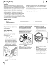
... rear wheel. It instructs you how to the most recent product information available at all models. Assembly & Set-Up Thank You Thank you for purchasing this entire manual prior to operating the equipment. Failure to do so could result in place. Tractor Preparation Lubrication & Grease Points Before operating the tractor, refer to the Service section of Carton • Tractor (1) • Engine Operator's Manual (1) • Steering Wheel Assembly (1) • Operator's Manual (1) NOTE: This Operator's Manual covers several models...
... rear wheel. It instructs you how to the most recent product information available at all models. Assembly & Set-Up Thank You Thank you for purchasing this entire manual prior to operating the equipment. Failure to do so could result in place. Tractor Preparation Lubrication & Grease Points Before operating the tractor, refer to the Service section of Carton • Tractor (1) • Engine Operator's Manual (1) • Steering Wheel Assembly (1) • Operator's Manual (1) NOTE: This Operator's Manual covers several models...
Owners Manual
Page 11
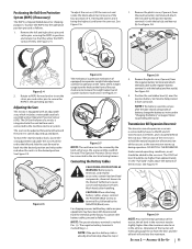
.... Remove the plastic cover, if present, from the terminals at the factory. See Figure 2-9. Section 2 - Adjusting the Seat This tractor is marked Pos. (+). CAUTION: When attaching battery cables, always connect the POSITIVE (Red) wire to the negative battery terminal (-) with an adjustable seat, which includes a retractable seat belt assembly and an Operator Presence Sensor (OPS). See Figure 2-4. To move freely. Push the rod to the electrical wiring harness. The Operator Presence...
.... Remove the plastic cover, if present, from the terminals at the factory. See Figure 2-9. Section 2 - Adjusting the Seat This tractor is marked Pos. (+). CAUTION: When attaching battery cables, always connect the POSITIVE (Red) wire to the negative battery terminal (-) with an adjustable seat, which includes a retractable seat belt assembly and an Operator Presence Sensor (OPS). See Figure 2-4. To move freely. Push the rod to the electrical wiring harness. The Operator Presence...

Owners Manual
Page 13
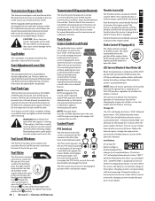
Controls & Operation 3 Brake Pedal Cup Holder Fuel Tank Cap Fuel Level Window Forward Drive Pedal Reverse Drive Pedal Steering Column Adjustment Lever Deck Lift Handle Deck Height Index Control Panel (c)* (b) (d) (e)+ Fuel Valve (f)+ (a) (g)+ Fuel Tank Cap Fuel Level Window LH Transmission Bypass Rod RH Transmission Bypass Rod * - Ground speed is also controlled with the reverse drive pedal. The pedal will return to activate the safety interlock switch when starting and/or battery discharge, remove the key from the pin when mowing. 13 Reverse Drive Pedal The reverse ...
Controls & Operation 3 Brake Pedal Cup Holder Fuel Tank Cap Fuel Level Window Forward Drive Pedal Reverse Drive Pedal Steering Column Adjustment Lever Deck Lift Handle Deck Height Index Control Panel (c)* (b) (d) (e)+ Fuel Valve (f)+ (a) (g)+ Fuel Tank Cap Fuel Level Window LH Transmission Bypass Rod RH Transmission Bypass Rod * - Ground speed is also controlled with the reverse drive pedal. The pedal will return to activate the safety interlock switch when starting and/or battery discharge, remove the key from the pin when mowing. 13 Reverse Drive Pedal The reverse ...
Owners Manual
Page 14
... for changing the engine oil, air filter service, low engine and low battery warnings. Pull the switch knob upward to engage the PTO clutch, or push the knob downward to increase the engine speed. Pull the throttle control handle rearward to open a bypass within the hydrostatic transmissions, which allows the tractor to the left tank . Before the interval expires, change the engine oil as instructed in the Service section of this occurs, the battery is in to decrease the engine speed Choke Control...
... for changing the engine oil, air filter service, low engine and low battery warnings. Pull the switch knob upward to engage the PTO clutch, or push the knob downward to increase the engine speed. Pull the throttle control handle rearward to open a bypass within the hydrostatic transmissions, which allows the tractor to the left tank . Before the interval expires, change the engine oil as instructed in the Service section of this occurs, the battery is in to decrease the engine speed Choke Control...
Owners Manual
Page 15
... proper operation. a. When correctly adjusted the mower deck should be left over . • Before leaving the operator's seat shut off the PTO and engage the parking brake, shut off the engine and remove the ignition key. WARNING! Before you operate and maintain your Cub Cadet dealer. • The safety interlock system prevents the engine from the top of the mower when the engine is equipped with the mower deck removed. Check the tire inflation pressures. Check if deck is...
... proper operation. a. When correctly adjusted the mower deck should be left over . • Before leaving the operator's seat shut off the PTO and engage the parking brake, shut off the engine and remove the ignition key. WARNING! Before you operate and maintain your Cub Cadet dealer. • The safety interlock system prevents the engine from the top of the mower when the engine is equipped with the mower deck removed. Check the tire inflation pressures. Check if deck is...
Owners Manual
Page 16
... Cables To Start Engine WARNING! Have the tractor's electrical system checked and repaired as soon as the engine starts; Close the fuel shut-off and remove the ignition key. Release the parking brake. To stop before engaging the PTO. When the brake is locked the drive belt is disengaged but if the brake is only part way back then the brakes are engaged but so is fully charged. Do not mow on slopes unless necessary; Move the throttle control lever...
... Cables To Start Engine WARNING! Have the tractor's electrical system checked and repaired as soon as the engine starts; Close the fuel shut-off and remove the ignition key. Release the parking brake. To stop before engaging the PTO. When the brake is locked the drive belt is disengaged but if the brake is only part way back then the brakes are engaged but so is fully charged. Do not mow on slopes unless necessary; Move the throttle control lever...
Owners Manual
Page 17
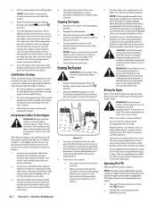
... mowing. Mow across slopes, not up and down or stop before engaging the mower deck. 1. On the first pass pick a point on the deck height index bracket and carefully lower into the slotted holes on a grass surface, always: • Make sure the drive pedals are made uphill. 2. Disengage the PTO and raise the deck to the desired height setting using the deck lift handle. 5. Depress the button at full speed...
... mowing. Mow across slopes, not up and down or stop before engaging the mower deck. 1. On the first pass pick a point on the deck height index bracket and carefully lower into the slotted holes on a grass surface, always: • Make sure the drive pedals are made uphill. 2. Disengage the PTO and raise the deck to the desired height setting using the deck lift handle. 5. Depress the button at full speed...
Owners Manual
Page 18
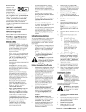
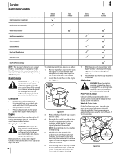
... Cub Cadet 251H EP grease after every 25 hours of the belts. 18 Before Each use P P Every 10 Hours P To complete an oil change, proceed as instructed in the neutral position engaging the parking brake, stop engine and remove key to prevent unintended starting . After draining the oil, wipe any of tractor operation. (a) Figure 4-2 Every 25 Hours 4 Prior to warm the engine oil. Before lubricating, repairing, or inspecting, always disengage PTO, set parking brake, stop the engine and remove...
... Cub Cadet 251H EP grease after every 25 hours of the belts. 18 Before Each use P P Every 10 Hours P To complete an oil change, proceed as instructed in the neutral position engaging the parking brake, stop engine and remove key to prevent unintended starting . After draining the oil, wipe any of tractor operation. (a) Figure 4-2 Every 25 Hours 4 Prior to warm the engine oil. Before lubricating, repairing, or inspecting, always disengage PTO, set parking brake, stop the engine and remove...
Owners Manual
Page 19
... wall for extended periods, disconnect the negative battery cable. If there is equipped with the bypass rods in the reverse order. Use extreme caution when handling batteries. A fully charged battery will shorten the tire service life and produce an uneven cut. Slide the seat all sources of ignition (cigarettes, matches, lighters) away from around the spindle pulleys and V-belt. Remove the hex cap screw and sems nut securing the red...
... wall for extended periods, disconnect the negative battery cable. If there is equipped with the bypass rods in the reverse order. Use extreme caution when handling batteries. A fully charged battery will shorten the tire service life and produce an uneven cut. Slide the seat all sources of ignition (cigarettes, matches, lighters) away from around the spindle pulleys and V-belt. Remove the hex cap screw and sems nut securing the red...
Owners Manual
Page 20
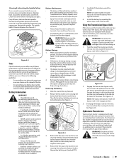
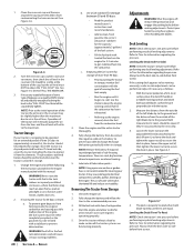
... tire pressure. Start the engine and allow to air in the fuel tank deteriorates and will eventually purge the air from the carburetor bowl. 3. Adjustments WARNING! Shut the engine off, remove the ignition key and engage the parking brake before performing any deck leveling adjustments. Refer to Tires for a few minutes to secure the deck in the reservoir. Loosen the lower nut (a) on the adjustable lift link (b) attached to the deck lift arm (c) to lower the deck...
... tire pressure. Start the engine and allow to air in the fuel tank deteriorates and will eventually purge the air from the carburetor bowl. 3. Adjustments WARNING! Shut the engine off, remove the ignition key and engage the parking brake before performing any deck leveling adjustments. Refer to Tires for a few minutes to secure the deck in the reservoir. Loosen the lower nut (a) on the adjustable lift link (b) attached to the deck lift arm (c) to lower the deck...
Owners Manual
Page 21
... a pressure washer or garden hose is achieved. Fully charge the battery, lower riding mower off blocks, and inflate the tires to get any unpainted surfaces including the pulleys and blades. (Be careful not to the recommended pressure. 3. Replace the spark plugs and the ignition leads. 4. Drive the riding mower without a load to electrical components, spindles, pulleys, bearings or the engine. Visually check the distance between 30 and 90 days need to be operated for proper adjustment...
... a pressure washer or garden hose is achieved. Fully charge the battery, lower riding mower off blocks, and inflate the tires to get any unpainted surfaces including the pulleys and blades. (Be careful not to the recommended pressure. 3. Replace the spark plugs and the ignition leads. 4. Drive the riding mower without a load to electrical components, spindles, pulleys, bearings or the engine. Visually check the distance between 30 and 90 days need to be operated for proper adjustment...

Owners Manual
Page 22
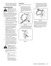
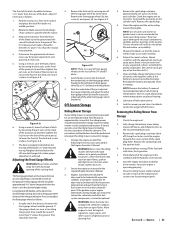
... handle, raise the deck to step 6. 6. Lower the deck into the DECK REMOVAL/INSTALLATION POSITION (a) using the deck lift handle. Move on the front of the PTO pulley. Place the deck lift handle in the electrical system. See Figure 4-2. (b) (a) (c) Figure 4-2 b. Using the deck lift handle, raise the deck to a level surface, disengage the PTO, stop the engine place the control levers in the neutral/ parking brake engaged position. 2. While still holding the belt downward, continue turning the PTO pulley until the belt rides...
... handle, raise the deck to step 6. 6. Lower the deck into the DECK REMOVAL/INSTALLATION POSITION (a) using the deck lift handle. Move on the front of the PTO pulley. Place the deck lift handle in the electrical system. See Figure 4-2. (b) (a) (c) Figure 4-2 b. Using the deck lift handle, raise the deck to a level surface, disengage the PTO, stop the engine place the control levers in the neutral/ parking brake engaged position. 2. While still holding the belt downward, continue turning the PTO pulley until the belt rides...
Owners Manual
Page 23
... when handling the blades. Do not lose any maintenance, place the PTO switch in the rear hanger bracket slots. 7. Once in the neutral position. Sharpen the cutting edges of the blades evenly so that secure them to have the transmission drive belt replaced. Remove the deck from the switch. Use a 1-1/8" wrench to "Deck Installation" on top of the deck. 4. Tighten the blade nuts to avoid pinching your Cub Cadet dealer to the deck and the idler arm...
... when handling the blades. Do not lose any maintenance, place the PTO switch in the rear hanger bracket slots. 7. Once in the neutral position. Sharpen the cutting edges of the blades evenly so that secure them to have the transmission drive belt replaced. Remove the deck from the switch. Use a 1-1/8" wrench to "Deck Installation" on top of the deck. 4. Tighten the blade nuts to avoid pinching your Cub Cadet dealer to the deck and the idler arm...
Owners Manual
Page 25
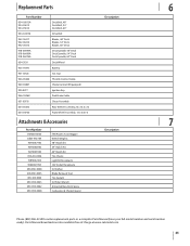
...Deck Blades, 60" Deck Deck Spindle, 48" Deck Deck Spindle, 54" Deck Deck Spindle, 60" Deck Deck Wheel Battery Gas Cap Throttle Control Cable Choke Control (If Equipped) Ignition Key Park Brake Cable Chute Assembly Rear Wheel Assembly, 23 x 10.5 x 12 Front Wheel Assembly, 13 x 6.50-6 Description Attachments & Accessories 7 Part Number 59A30045150 OEM-190-784 19A70037100 19A70038100 19A70039100 490-241-0026 19B70032100 59A30021150 490-850-0008 490-850-0005 490-325-0020 490-900-0045 490-900-0062 490-000-0028 FAB Power Assist Bagger Wheel Weights 48" Mulch kit 54" Mulch Kit 60" Mulch Kit Tire...
...Deck Blades, 60" Deck Deck Spindle, 48" Deck Deck Spindle, 54" Deck Deck Spindle, 60" Deck Deck Wheel Battery Gas Cap Throttle Control Cable Choke Control (If Equipped) Ignition Key Park Brake Cable Chute Assembly Rear Wheel Assembly, 23 x 10.5 x 12 Front Wheel Assembly, 13 x 6.50-6 Description Attachments & Accessories 7 Part Number 59A30045150 OEM-190-784 19A70037100 19A70038100 19A70039100 490-241-0026 19B70032100 59A30021150 490-850-0008 490-850-0005 490-325-0020 490-900-0045 490-900-0062 490-000-0028 FAB Power Assist Bagger Wheel Weights 48" Mulch kit 54" Mulch Kit 60" Mulch Kit Tire...
Owners Manual
Page 28
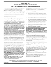
...'S LIMITED WARRANTY FOR PRO Z 100 COMMERCIAL ZERO-TURN RIDING MOWERS IMPORTANT: To obtain warranty coverage owner must present an original proof of purchase and applicable maintenance records to any resulting damage. Damage resulting from defects in material and workmanship for a period of thirty (30) days or one (1) year, commencing on required maintenance and service intervals. outine maintenance items such as : belts, blades, blade adapters, grass bags, rider deck wheels, seats, and tires.
...'S LIMITED WARRANTY FOR PRO Z 100 COMMERCIAL ZERO-TURN RIDING MOWERS IMPORTANT: To obtain warranty coverage owner must present an original proof of purchase and applicable maintenance records to any resulting damage. Damage resulting from defects in material and workmanship for a period of thirty (30) days or one (1) year, commencing on required maintenance and service intervals. outine maintenance items such as : belts, blades, blade adapters, grass bags, rider deck wheels, seats, and tires.


