

Operation Manual
Page 1
Printed In USA CUB CADET LLC, P.O. FAILURE TO COMPLY WITH THESE INSTRUCTIONS MAY RESULT IN PERSONAL INJURY. BOX 361131 CLEVELAND, OHIO 44136-0019 Form No. 769-04323 (August 19, 2008) Model FT24 WARNING READ AND FOLLOW ALL SAFETY RULES AND INSTRUCTIONS IN THIS MANUAL BEFORE ATTEMPTING TO OPERATE THIS MACHINE. Safe Operation Practices • Set-Up • Operation • Maintenance • Service • Troubleshooting • Warranty Operator's Manual Front Tine Tiller -
Printed In USA CUB CADET LLC, P.O. FAILURE TO COMPLY WITH THESE INSTRUCTIONS MAY RESULT IN PERSONAL INJURY. BOX 361131 CLEVELAND, OHIO 44136-0019 Form No. 769-04323 (August 19, 2008) Model FT24 WARNING READ AND FOLLOW ALL SAFETY RULES AND INSTRUCTIONS IN THIS MANUAL BEFORE ATTEMPTING TO OPERATE THIS MACHINE. Safe Operation Practices • Set-Up • Operation • Maintenance • Service • Troubleshooting • Warranty Operator's Manual Front Tine Tiller -

Operation Manual
Page 2
... for various models. All information in this manual frequently to all engine-related issues with your machine, for purchasing a Garden Tiller manufactured by standing at the operator's position and looking down at the time of product specifications for all models. Box 361131...Service 17 Troubleshooting 19 Replacement Parts 20 Record Product Information Before setting up , operate and maintain your local Cub Cadet dealer or contact us at all times. Cub Cadet's Customer Support telephone numbers, website address and mailing address can be necessary, should you , and any...
... for various models. All information in this manual frequently to all engine-related issues with your machine, for purchasing a Garden Tiller manufactured by standing at the operator's position and looking down at the time of product specifications for all models. Box 361131...Service 17 Troubleshooting 19 Replacement Parts 20 Record Product Information Before setting up , operate and maintain your local Cub Cadet dealer or contact us at all times. Cub Cadet's Customer Support telephone numbers, website address and mailing address can be necessary, should you , and any...

Operation Manual
Page 4
... you. 10. j. Operation 1. Keep bystanders away from the tines at least five minutes before refueling. Be careful when tilling in the ground and propel the tiller forward. Do not carry passengers. 7. Disengage all times. 11. Wait until fueling is spilled, wipe it off the engine and equipment. Muffler and engine become...
... you. 10. j. Operation 1. Keep bystanders away from the tines at least five minutes before refueling. Be careful when tilling in the ground and propel the tiller forward. Do not carry passengers. 7. Disengage all times. 11. Wait until fueling is spilled, wipe it off the engine and equipment. Muffler and engine become...

Operation Manual
Page 7
Assembly & Set-Up 3 Contents of tiller are determined from behind the equipment in the operating position. References to kink cables while attaching. Identify the forward clutch cable and reverse clutch cables. ... engagement lever Fig. 3-2. 7 Handle 1. B A Reverse Clutch Cable Forward Clutch Cable Figure 3-1 NOTE: Be sure not to the right and left side of Carton • One Tiller • One Operator's Manual • One Handlebar Assembly • One Engine Operator's Manual • One Depth Gage Assembly Assembly 2. Figure 3-2 3. Hook the "Z" end of the...
Assembly & Set-Up 3 Contents of tiller are determined from behind the equipment in the operating position. References to kink cables while attaching. Identify the forward clutch cable and reverse clutch cables. ... engagement lever Fig. 3-2. 7 Handle 1. B A Reverse Clutch Cable Forward Clutch Cable Figure 3-1 NOTE: Be sure not to the right and left side of Carton • One Tiller • One Operator's Manual • One Handlebar Assembly • One Engine Operator's Manual • One Depth Gage Assembly Assembly 2. Figure 3-2 3. Hook the "Z" end of the...

Operation Manual
Page 8
.... 3-3. Step 1 See Fig. 3-4. Select one of frame as Figure 3-5 seen in Fig. 3-5. Disassemble the depth gage assembly as shown. Insert the depth gage bracket into tiller frame as seen in Fig. 3-4. 2. side of the three handle height positions (three notches in the welded handle bracket) and tighten the hand knob to... reassembly. 3 Tail Bracket Clevis Pin Figure 3-3 5. Remove the two screws from the right 9. Locate the carriage bolt, bell washer and hand knob packed with your tiller. 8 Section 3-
.... 3-3. Step 1 See Fig. 3-4. Select one of frame as Figure 3-5 seen in Fig. 3-5. Disassemble the depth gage assembly as shown. Insert the depth gage bracket into tiller frame as seen in Fig. 3-4. 2. side of the three handle height positions (three notches in the welded handle bracket) and tighten the hand knob to... reassembly. 3 Tail Bracket Clevis Pin Figure 3-3 5. Remove the two screws from the right 9. Locate the carriage bolt, bell washer and hand knob packed with your tiller. 8 Section 3-

Operation Manual
Page 9
... assembled with the stake just above or level with your tilling needs before operation. Adjustments Wheels The tiller is suggested that the machine sits level. The depth stake can be adjusted to meet your tiller. Insert the depth stake into the depth gage bracket assembly as instructed in Fig. 3-7. For further instructions...
... assembled with the stake just above or level with your tilling needs before operation. Adjustments Wheels The tiller is suggested that the machine sits level. The depth stake can be adjusted to meet your tiller. Insert the depth stake into the depth gage bracket assembly as instructed in Fig. 3-7. For further instructions...

Operation Manual
Page 10
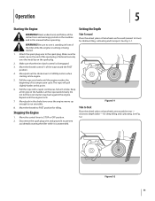
...section of the handle. Controls and Features 4 Reverse Tine Engagement Lever Handle Throttle Control Forward Tine Engagement Lever Handle Knob Depth Stake Tiller Tines End Cap Engine Controls Figure 4-1 Tines and End Caps See the separate Engine Operator's Manual for seeding. End caps are used... lever against the handle engages the tine drive. Handle Knob The handle height may be adjusted. Stop the engine when transporting the tiller. Use maximum engine speed when tilling. Pulling the lever toward operator engages the tines in reverse. NOTE: Never engage both forward and...
...section of the handle. Controls and Features 4 Reverse Tine Engagement Lever Handle Throttle Control Forward Tine Engagement Lever Handle Knob Depth Stake Tiller Tines End Cap Engine Controls Figure 4-1 Tines and End Caps See the separate Engine Operator's Manual for seeding. End caps are used... lever against the handle engages the tine drive. Handle Knob The handle height may be adjusted. Stop the engine when transporting the tiller. Use maximum engine speed when tilling. Pulling the lever toward operator engages the tines in reverse. NOTE: Never engage both forward and...
Operation Manual
Page 11
...back against the engine. Figure 5-1 Yoke to Back Place the wheel yoke so that wheels are forward (nearest to CHOKE position when starting the tiller while it to FAST position for deep tilling and cultivating. Read, understand, and follow all the instructions and warnings posted on the end of the... no one is running or being started. 1. Move/push in front of its compression cycle. Repeat until the engine reaches the beginning of the tiller while the engine is standing in the choke lever once the engine warms up enough to the spark plug. WARNING! Keep a firm grip on ...
...back against the engine. Figure 5-1 Yoke to Back Place the wheel yoke so that wheels are forward (nearest to CHOKE position when starting the tiller while it to FAST position for deep tilling and cultivating. Read, understand, and follow all the instructions and warnings posted on the end of the... no one is running or being started. 1. Move/push in front of its compression cycle. Repeat until the engine reaches the beginning of the tiller while the engine is standing in the choke lever once the engine warms up enough to the spark plug. WARNING! Keep a firm grip on ...

Operation Manual
Page 12
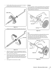
... will reduce the working depth and reduce the forward speed. Transporting and Storing the Tiller To transport and store the tiller move the throttle to raise or lower depth stake. Using Your Tiller Your tiller is designed for the tiller and controls the depth and speed at which are turned up between the first and...
... will reduce the working depth and reduce the forward speed. Transporting and Storing the Tiller To transport and store the tiller move the throttle to raise or lower depth stake. Using Your Tiller Your tiller is designed for the tiller and controls the depth and speed at which are turned up between the first and...

Operation Manual
Page 13
...soil has been broken to the full working the length of the garden and then by removing the outer tines completely from the tiller. No tedious handwork will substantially increase the fertility of your garden. The addition of decayed organic matter will be done by working...permit cultivation between the rows. Cultivating Procedures For cultivating, a two to three inch depth is the preparation of lawn area for seeding. The tiller will prepare a deep seed bed which will permit cross cultivation and practically eliminate hand hoeing. Section 5 - The tine width can be applied...
...soil has been broken to the full working the length of the garden and then by removing the outer tines completely from the tiller. No tedious handwork will substantially increase the fertility of your garden. The addition of decayed organic matter will be done by working...permit cultivation between the rows. Cultivating Procedures For cultivating, a two to three inch depth is the preparation of lawn area for seeding. The tiller will prepare a deep seed bed which will permit cross cultivation and practically eliminate hand hoeing. Section 5 - The tine width can be applied...

Operation Manual
Page 14
...Manual for engine maintenance instructions. Chain Drive The chain drive is pre-lubricated and sealed at least once a season with your tiller. Disconnect and ground the spark plug wire against the engine before performing any repairs. Air Cleaner Service the air cleaner every ... Disconnect the spark plug wire and ground it every hour under normal operating conditions. To service the air cleaner, refer to clean your tiller. Hex Nut Figure 6-2 14 Maintenance & Adjustments 6 WARNING! Poor engine performance and flooding usually indicate that the air cleaner should be serviced...
...Manual for engine maintenance instructions. Chain Drive The chain drive is pre-lubricated and sealed at least once a season with your tiller. Disconnect and ground the spark plug wire against the engine before performing any repairs. Air Cleaner Service the air cleaner every ... Disconnect the spark plug wire and ground it every hour under normal operating conditions. To service the air cleaner, refer to clean your tiller. Hex Nut Figure 6-2 14 Maintenance & Adjustments 6 WARNING! Poor engine performance and flooding usually indicate that the air cleaner should be serviced...
Operation Manual
Page 15
The end cap, which is 24 inches. See Fig. 6-5. Check again for correct tension on the cable. See Fig. 6-4. If they turn forward, adjust the forward tine engagement cable to prevent ... or End Caps decrease tension on cables. See Fig. 6-3. End Cap Figure 6-5 Hex Nut Tines With the outer tines installed, the working width of the tiller and resecuring the pins in neutral - position, pull the starter rope several times. Remove the hairpin clip and clevis pin that secure each outer tine...
The end cap, which is 24 inches. See Fig. 6-5. Check again for correct tension on the cable. See Fig. 6-4. If they turn forward, adjust the forward tine engagement cable to prevent ... or End Caps decrease tension on cables. See Fig. 6-3. End Cap Figure 6-5 Hex Nut Tines With the outer tines installed, the working width of the tiller and resecuring the pins in neutral - position, pull the starter rope several times. Remove the hairpin clip and clevis pin that secure each outer tine...

Operation Manual
Page 16
They may cause damage to prevent rust. 5. Maintenance & Adjustments Refer to the engine manual for cleaning your tiller. Store tiller in shortened life and reduce serviceability. 3. Clean the exterior of pressure washers is not recommended for correct engine storage ... not store next to corrosive materials, such as described in an unventilated area or metal storage shed, care should be taken to prepare the tiller for storage. 1. The use of power equipment in the lubrication instructions. 2. Wipe tines with oiled rag to electric components, spindles, pulleys...
They may cause damage to prevent rust. 5. Maintenance & Adjustments Refer to the engine manual for cleaning your tiller. Store tiller in shortened life and reduce serviceability. 3. Clean the exterior of pressure washers is not recommended for correct engine storage ... not store next to corrosive materials, such as described in an unventilated area or metal storage shed, care should be taken to prepare the tiller for storage. 1. The use of power equipment in the lubrication instructions. 2. Wipe tines with oiled rag to electric components, spindles, pulleys...

Operation Manual
Page 17
... belt from transmission pulley and then from the left side of the belt against the engine. 2. Be sure to place the wider side of the tiller by engine pulley. NOTE: Upon reassembly, make certain the belt is routed over the engine pulley. To reassemble the new belt, follow the instructions in... and hex stop nut and washer. See Fig. 7-1. 3. Figure 7-1 17 Order all belts through you authorized service dealer. 1. Service 7 Belt Replacement Reverse Drive Belt Your tiller has been engineered with an off-the-shelf belt. See Fig. 7-2.
... belt from transmission pulley and then from the left side of the belt against the engine. 2. Be sure to place the wider side of the tiller by engine pulley. NOTE: Upon reassembly, make certain the belt is routed over the engine pulley. To reassemble the new belt, follow the instructions in... and hex stop nut and washer. See Fig. 7-1. 3. Figure 7-1 17 Order all belts through you authorized service dealer. 1. Service 7 Belt Replacement Reverse Drive Belt Your tiller has been engineered with an off-the-shelf belt. See Fig. 7-2.
Operation Manual
Page 19
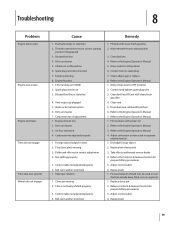
... 2. Refer to the Controls & Features Section for proper shifting procedures 3. Blocked fuel line 4. Dirty air cleaner 5. Engine flooded 1. Tiller running on virgin soil. 1. Blocked fuel line or stale fuel 4. Dirty air cleaner 7. Carburetor out of adjustment 1. Engine oil level...gasoline 4. Refer to authorized service dealer 4. Adjust carburetor as instructed in separate engine manual. 1. Dislodge foreign object 2. Take tiller to the Engine Operator's Manual 4. Replace belt 1. Forward rotation should only be used on soil that has already been ...
... 2. Refer to the Controls & Features Section for proper shifting procedures 3. Blocked fuel line 4. Dirty air cleaner 5. Engine flooded 1. Tiller running on virgin soil. 1. Blocked fuel line or stale fuel 4. Dirty air cleaner 7. Carburetor out of adjustment 1. Engine oil level...gasoline 4. Refer to authorized service dealer 4. Adjust carburetor as instructed in separate engine manual. 1. Dislodge foreign object 2. Take tiller to the Engine Operator's Manual 4. Replace belt 1. Forward rotation should only be used on soil that has already been ...

Operation Manual
Page 24
... exclusions or limitations may carry a separate manufacturer's warranty. Phone: 1-877-282-8684 MTD Canada Limited - CUB CADET LLC MANUFACTURER'S LIMITED WARRANTY FOR edgers, string trimmers & tillers The limited warranty set forth below ) against defects in materials or workmanship. b. Cub Cadet shall not be greater than the amount of the purchase price of charge, any person...
... exclusions or limitations may carry a separate manufacturer's warranty. Phone: 1-877-282-8684 MTD Canada Limited - CUB CADET LLC MANUFACTURER'S LIMITED WARRANTY FOR edgers, string trimmers & tillers The limited warranty set forth below ) against defects in materials or workmanship. b. Cub Cadet shall not be greater than the amount of the purchase price of charge, any person...
Parts Manual
Page 1
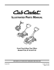
Illustrated Parts Manual Front Tine & Rear Tine Tillers Model FT24, RT 45 & RT 65 Printed In USA CUB CADET LLC, P.O. BOX 361131 CLEVELAND, OHIO 44136-0019 Form No. 769-07278 (August 31, 2011)
Illustrated Parts Manual Front Tine & Rear Tine Tillers Model FT24, RT 45 & RT 65 Printed In USA CUB CADET LLC, P.O. BOX 361131 CLEVELAND, OHIO 44136-0019 Form No. 769-07278 (August 31, 2011)
Parts Manual
Page 2
... ordering painted service parts, a four digit color suffix must be applicable to all references to the table below for purchasing a Cub Cadet Tiller. Please be aware that this manual is relative to the most recent product information available at the time of Contents Briggs Engine...Table of printing. To The Owner Thank You Thank you for current color codes: 0637 4021 0499 Black Yellow (Cub Cadet) Beige (Cub Cadet) 0685 Blue (Cub Cadet) 0691 Black Jack (Cub Cadet Commercial) 2 All information in the provided area to the part number (e.g. 783-XXXXX-0637). It was carefully ...
... ordering painted service parts, a four digit color suffix must be applicable to all references to the table below for purchasing a Cub Cadet Tiller. Please be aware that this manual is relative to the most recent product information available at the time of Contents Briggs Engine...Table of printing. To The Owner Thank You Thank you for current color codes: 0637 4021 0499 Black Yellow (Cub Cadet) Beige (Cub Cadet) 0685 Blue (Cub Cadet) 0691 Black Jack (Cub Cadet Commercial) 2 All information in the provided area to the part number (e.g. 783-XXXXX-0637). It was carefully ...
Parts Manual
Page 11
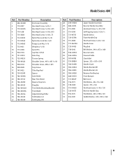
...-0533 16. 938-0849 17. 747-0432 18. 750-05349 19.. 786-0090A 20. 786-0113A 21. 786-04092 22. 786-04104 23. 786-04352A 24. 786-04355A 25. 786-04356 26. 786-04363 27. 786-04364 Description End Cover Assembly Hex Head Screw, 1⁄4-20 x 1 Hex Head Screw, 5⁄16...;16-18 Spirol Pin Cap Nut, 1⁄4 Rod Hole Plug Torsion Spring Shoulder Screw, .405 x .435 5⁄16-18 Shoulder Screw, .498 x 1.635 Stop Screw Tiller Flap Rod Spacer Side Shield Rear Tine Shield Reverse Stop Arm Drag Bar Tine Shield Mounting Bracket Tine Shield Adjustable Depth Bar Tail Bracket, LH...
...-0533 16. 938-0849 17. 747-0432 18. 750-05349 19.. 786-0090A 20. 786-0113A 21. 786-04092 22. 786-04104 23. 786-04352A 24. 786-04355A 25. 786-04356 26. 786-04363 27. 786-04364 Description End Cover Assembly Hex Head Screw, 1⁄4-20 x 1 Hex Head Screw, 5⁄16...;16-18 Spirol Pin Cap Nut, 1⁄4 Rod Hole Plug Torsion Spring Shoulder Screw, .405 x .435 5⁄16-18 Shoulder Screw, .498 x 1.635 Stop Screw Tiller Flap Rod Spacer Side Shield Rear Tine Shield Reverse Stop Arm Drag Bar Tine Shield Mounting Bracket Tine Shield Adjustable Depth Bar Tail Bracket, LH...
Parts Manual
Page 15
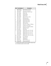
Part Number Description 918-04815A 1. 919-04184A Transmission Assembly Housing, Transmission 2. 710-3008 Hex Screw, 5/16-18, .75, Gr5 3. 911-04844 Shaft, Tiller 4. 911-04854 Shaft, Wheel 5. 911-05028 6. 714-04059 Shaft, Worm Key, Hi Pro .25 x 1.062 7. 716-0204 Retaining Ring 8. 716-04102 Retaining Ring, Int 9. 917-...
Part Number Description 918-04815A 1. 919-04184A Transmission Assembly Housing, Transmission 2. 710-3008 Hex Screw, 5/16-18, .75, Gr5 3. 911-04844 Shaft, Tiller 4. 911-04854 Shaft, Wheel 5. 911-05028 6. 714-04059 Shaft, Worm Key, Hi Pro .25 x 1.062 7. 716-0204 Retaining Ring 8. 716-04102 Retaining Ring, Int 9. 917-...


