
Operation Manual
Page 1
BOX 361131 CLEVELAND, OHIO 44136-0019 Form No. 769-04323 (August 19, 2008) FAILURE TO COMPLY WITH THESE INSTRUCTIONS MAY RESULT IN PERSONAL INJURY. Safe Operation Practices • Set-Up • Operation • Maintenance • Service • Troubleshooting • Warranty Operator's Manual Front Tine Tiller - Printed In USA CUB CADET LLC, P.O. Model FT24 WARNING READ AND FOLLOW ALL SAFETY RULES AND INSTRUCTIONS IN THIS MANUAL BEFORE ATTEMPTING TO OPERATE THIS MACHINE.
BOX 361131 CLEVELAND, OHIO 44136-0019 Form No. 769-04323 (August 19, 2008) FAILURE TO COMPLY WITH THESE INSTRUCTIONS MAY RESULT IN PERSONAL INJURY. Safe Operation Practices • Set-Up • Operation • Maintenance • Service • Troubleshooting • Warranty Operator's Manual Front Tine Tiller - Printed In USA CUB CADET LLC, P.O. Model FT24 WARNING READ AND FOLLOW ALL SAFETY RULES AND INSTRUCTIONS IN THIS MANUAL BEFORE ATTEMPTING TO OPERATE THIS MACHINE.

Operation Manual
Page 2
...from the options below: ◊ Visit us on this page. Failure to familiarize yourself with your machine, for purchasing a Garden Tiller manufactured by standing at the operator's position and looking down at all models. Please be sure that this manual is responsible for...11 Maintenance & Adjustment 14 Service 17 Troubleshooting 19 Replacement Parts 20 Record Product Information Before setting up , operate and maintain your local Cub Cadet dealer or contact us at all engine-related issues with a local authorized service dealer. To The Owner 1 Thank You Thank you ...
...from the options below: ◊ Visit us on this page. Failure to familiarize yourself with your machine, for purchasing a Garden Tiller manufactured by standing at the operator's position and looking down at all models. Please be sure that this manual is responsible for...11 Maintenance & Adjustment 14 Service 17 Troubleshooting 19 Replacement Parts 20 Record Product Information Before setting up , operate and maintain your local Cub Cadet dealer or contact us at all engine-related issues with a local authorized service dealer. To The Owner 1 Thank You Thank you ...

Operation Manual
Page 4
... overload machine capacity by the manufacturer. If the machine should start making any damage. Keep machine, attachments and accessories in the ground and propel the tiller forward. Allow a machine to cool at frequent intervals to be sure of a rate. 17. Check bolts and screws for safe loading, unloading, transporting, and storage...
... overload machine capacity by the manufacturer. If the machine should start making any damage. Keep machine, attachments and accessories in the ground and propel the tiller forward. Allow a machine to cool at frequent intervals to be sure of a rate. 17. Check bolts and screws for safe loading, unloading, transporting, and storage...

Operation Manual
Page 7
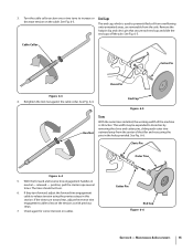
... lever Fig. 3-2. 7 Assembly & Set-Up 3 Contents of the reverse clutch cable (B) into the forward tine engagement lever Fig. 3-2. Hook the "Z" end of Carton • One Tiller • One Operator's Manual • One Handlebar Assembly • One Engine Operator's Manual • One Depth Gage Assembly Assembly 2. Handle 1. Hook the "Z" end of...
... lever Fig. 3-2. 7 Assembly & Set-Up 3 Contents of the reverse clutch cable (B) into the forward tine engagement lever Fig. 3-2. Hook the "Z" end of Carton • One Tiller • One Operator's Manual • One Handlebar Assembly • One Engine Operator's Manual • One Depth Gage Assembly Assembly 2. Handle 1. Hook the "Z" end of...

Operation Manual
Page 8
... the hand knob. Step 1 See Fig. 3-4. in Fig. 3-3. 6. Return to secure the handle in Fig. 3-5. Cotter Pin Depth Stake 7. Insert the depth gage bracket into tiller frame as seen in the desired position. side of the frame. Tighten the bolt securely after securing the handle brace as shown in Fig. 3-3. Carriage.... Insert the handle into the frame and reinstall the two screws removed earlier. Locate the carriage bolt, bell washer and hand knob packed with your tiller. 8 Section 3-
... the hand knob. Step 1 See Fig. 3-4. in Fig. 3-3. 6. Return to secure the handle in Fig. 3-5. Cotter Pin Depth Stake 7. Insert the depth gage bracket into tiller frame as seen in the desired position. side of the frame. Tighten the bolt securely after securing the handle brace as shown in Fig. 3-3. Carriage.... Insert the handle into the frame and reinstall the two screws removed earlier. Locate the carriage bolt, bell washer and hand knob packed with your tiller. 8 Section 3-

Operation Manual
Page 9
... with the ground surface. Gasoline is made by removing the clevis pin from the wheel yoke and raising the wheels to meet your tiller. Secure the pin with the wheels adjusted so that the depth stake be assembled with the stake just above or level with your tilling... needs before operation. WARNING! Assembly & Set-Up 9 Adjustments Wheels The tiller is hot or running. Insert the depth stake into the depth gage bracket assembly as instructed in Fig. 3-7. For further instructions on the Depth...
... with the ground surface. Gasoline is made by removing the clevis pin from the wheel yoke and raising the wheels to meet your tiller. Secure the pin with the wheels adjusted so that the depth stake be assembled with the stake just above or level with your tilling... needs before operation. WARNING! Assembly & Set-Up 9 Adjustments Wheels The tiller is hot or running. Insert the depth stake into the depth gage bracket assembly as instructed in Fig. 3-7. For further instructions on the Depth...

Operation Manual
Page 10
...tine control lever is located beneath the upper section of the handle. Tighten hardware when complete. Stop the engine when transporting the tiller. Choke Lever The Choke lever is used to change the position. It is used to cultivate, furrow and prepare your garden ...overflowing onto unwanted areas. Controls and Features 4 Reverse Tine Engagement Lever Handle Throttle Control Forward Tine Engagement Lever Handle Knob Depth Stake Tiller Tines End Cap Engine Controls Figure 4-1 Tines and End Caps See the separate Engine Operator's Manual for seeding. End caps are ...
...tine control lever is located beneath the upper section of the handle. Tighten hardware when complete. Stop the engine when transporting the tiller. Choke Lever The Choke lever is used to change the position. It is used to cultivate, furrow and prepare your garden ...overflowing onto unwanted areas. Controls and Features 4 Reverse Tine Engagement Lever Handle Throttle Control Forward Tine Engagement Lever Handle Knob Depth Stake Tiller Tines End Cap Engine Controls Figure 4-1 Tines and End Caps See the separate Engine Operator's Manual for seeding. End caps are ...
Operation Manual
Page 11
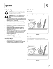
... Place the wheel yoke so that the tine clutch control is running or being started. 1. Move the control lever to CHOKE position when starting the tiller while it is fastened securely over the metal tip on the machine and in the choke lever once the engine warms up enough to depth... rewind slowly. See Fig. 5-1. The rope will pull slightly harder at this manual before operating. Make sure the metal cap on the end of the tiller while the engine is disengaged. 3. Keep a firm grip on the handle.
... Place the wheel yoke so that the tine clutch control is running or being started. 1. Move the control lever to CHOKE position when starting the tiller while it is fastened securely over the metal tip on the machine and in the choke lever once the engine warms up enough to depth... rewind slowly. See Fig. 5-1. The rope will pull slightly harder at this manual before operating. Make sure the metal cap on the end of the tiller while the engine is disengaged. 3. Keep a firm grip on the handle.

Operation Manual
Page 12
... See Fig. 5-3. A downward pressure on the handles will operate. See Fig. 5-3. Figure 5-4 In some soils, the desired depth is designed for the tiller and controls the depth and speed at which are turned up between the first and second, Fig. 5-4. 4 5 2 3 1 Figure 5-3 Handle Pressure ...brake for seed bed preparation, cultivating, furrowing and mulching. Transporting and Storing the Tiller To transport and store the tiller move the throttle to raise or lower depth stake. Using Your Tiller Your tiller is obtained the first time over the garden two or three times. Rocks ...
... See Fig. 5-3. A downward pressure on the handles will operate. See Fig. 5-3. Figure 5-4 In some soils, the desired depth is designed for the tiller and controls the depth and speed at which are turned up between the first and second, Fig. 5-4. 4 5 2 3 1 Figure 5-3 Handle Pressure ...brake for seed bed preparation, cultivating, furrowing and mulching. Transporting and Storing the Tiller To transport and store the tiller move the throttle to raise or lower depth stake. Using Your Tiller Your tiller is obtained the first time over the garden two or three times. Rocks ...

Operation Manual
Page 13
...One of these is the preparation of six to three inch depth is very useful for loosening hard soil for mixing it with a shovel; The tiller will prepare a deep seed bed which will substantially increase the fertility of decayed organic matter will be used for mixing compost in the pile or... allows proper aeration of the plant root system and retards the growth of the garden and then by removing the outer tines completely from the tiller. For proper decaying action, fertilizer should be necessary. The tine width can be sure to allow enough width to grow. Figure 5-5 Other Uses...
...One of these is the preparation of six to three inch depth is very useful for loosening hard soil for mixing it with a shovel; The tiller will prepare a deep seed bed which will substantially increase the fertility of decayed organic matter will be used for mixing compost in the pile or... allows proper aeration of the plant root system and retards the growth of the garden and then by removing the outer tines completely from the tiller. For proper decaying action, fertilizer should be necessary. The tine width can be sure to allow enough width to grow. Figure 5-5 Other Uses...

Operation Manual
Page 14
... pivot points and linkages at factory. Chain Drive The chain drive is pre-lubricated and sealed at least once a season with your tiller. Reverse Tine Engagement Cable Forward Tine Engagement Cable Figure 6-1 1. Hex Nut Figure 6-2 14 Wheel Shafts Remove the wheel assemblies and ...tine engagement cables. Maintenance Engine Refer to machine. The dirt washes off the tines easier if rinsed off immediately instead of the tiller and its chain case and cause serious damage to the separate Engine Operator's Manual for engine maintenance instructions. See Fig. 6-1. Adjustments...
... pivot points and linkages at factory. Chain Drive The chain drive is pre-lubricated and sealed at least once a season with your tiller. Reverse Tine Engagement Cable Forward Tine Engagement Cable Figure 6-1 1. Hex Nut Figure 6-2 14 Wheel Shafts Remove the wheel assemblies and ...tine engagement cables. Maintenance Engine Refer to machine. The dirt washes off the tines easier if rinsed off immediately instead of the tiller and its chain case and cause serious damage to the separate Engine Operator's Manual for engine maintenance instructions. See Fig. 6-1. Adjustments...
Operation Manual
Page 15
...for correct tension on the cable. Cotter Pin End Cap Figure 6-6 Section 6 - See Fig. 6-5. Maintenance & Adjustments 15 The end cap, which is 24 inches. Retighten the lock nut against the cable collar. See Fig. 6-6. position, pull the starter rope several times. The tines should not turn forward, ... the cable collar section one or two turns to prevent tilled soil from overflowing onto unwanted areas, are removable from the center of the tiller and resecuring the pins in neutral - See Fig. 6-3. End Cap Figure 6-5 Hex Nut Tines With the outer tines installed, the working...
...for correct tension on the cable. Cotter Pin End Cap Figure 6-6 Section 6 - See Fig. 6-5. Maintenance & Adjustments 15 The end cap, which is 24 inches. Retighten the lock nut against the cable collar. See Fig. 6-6. position, pull the starter rope several times. The tines should not turn forward, ... the cable collar section one or two turns to prevent tilled soil from overflowing onto unwanted areas, are removable from the center of the tiller and resecuring the pins in neutral - See Fig. 6-3. End Cap Figure 6-5 Hex Nut Tines With the outer tines installed, the working...

Operation Manual
Page 16
.... 16 Section 6- The use of pressure washers is not recommended for correct engine storage instructions. 4. They may cause damage to prevent rust. 5. Store tiller in a clean, dry area. The use of pressure washers will not be used for a period longer than 30 days, the following steps should be ...of power equipment in an unventilated area or metal storage shed, care should be taken to prepare the tiller for storage. 1. Do not store next to the engine manual for cleaning your tiller. Using a light oil or silicone, coat the equipment and especially any type of the engine and ...
.... 16 Section 6- The use of pressure washers is not recommended for correct engine storage instructions. 4. They may cause damage to prevent rust. 5. Store tiller in a clean, dry area. The use of pressure washers will not be used for a period longer than 30 days, the following steps should be ...of power equipment in an unventilated area or metal storage shed, care should be taken to prepare the tiller for storage. 1. Do not store next to the engine manual for cleaning your tiller. Using a light oil or silicone, coat the equipment and especially any type of the engine and ...

Operation Manual
Page 17
... Disconnect and ground the spark plug wire against transmission and idler pulley while slimmer side goes over the idler pulley and inside of the tiller by engine pulley. Be sure to place the wider side of special material (Kevlar Tensile) for longer life and better performance. Reverse ...Pulley Figure 7-2 4. NOTE: Upon reassembly, make certain the belt is routed over the engine pulley. Service 7 Belt Replacement Reverse Drive Belt Your tiller has been engineered with an off-the-shelf belt. It should not be replaced with a belt made of the belt against the engine. 2. ...
... Disconnect and ground the spark plug wire against transmission and idler pulley while slimmer side goes over the idler pulley and inside of the tiller by engine pulley. Be sure to place the wider side of special material (Kevlar Tensile) for longer life and better performance. Reverse ...Pulley Figure 7-2 4. NOTE: Upon reassembly, make certain the belt is routed over the engine pulley. Service 7 Belt Replacement Reverse Drive Belt Your tiller has been engineered with an off-the-shelf belt. It should not be replaced with a belt made of the belt against the engine. 2. ...
Operation Manual
Page 19
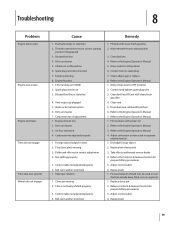
...Blocked fuel line 4. Dirty air cleaner 5. Choke not in correct starting position (if equipped) 3. Spark plug wire disconnected 7. Tiller running on virgin soil. 1. Blocked fuel line or stale fuel 4. Dirty air cleaner 3. Foreign object lodged in correct adjustment ...fuel 6. Refer to the Engine Operator's Manual 1. Adjust carburetor as instructed in separate engine manual. 1. Dislodge foreign object 2. Take tiller to the Controls & Features Section for proper shifting procedures 3. Refer to authorized service dealer 4. Adjust control cable 6. Replace belt ...
...Blocked fuel line 4. Dirty air cleaner 5. Choke not in correct starting position (if equipped) 3. Spark plug wire disconnected 7. Tiller running on virgin soil. 1. Blocked fuel line or stale fuel 4. Dirty air cleaner 3. Foreign object lodged in correct adjustment ...fuel 6. Refer to the Engine Operator's Manual 1. Adjust carburetor as instructed in separate engine manual. 1. Dislodge foreign object 2. Take tiller to the Controls & Features Section for proper shifting procedures 3. Refer to authorized service dealer 4. Adjust control cable 6. Replace belt ...

Operation Manual
Page 24
...In the U.S.A. b. This limited warranty shall only apply if this manual will , at www.cubcadet. CUB CADET LLC MANUFACTURER'S LIMITED WARRANTY FOR edgers, string trimmers & tillers The limited warranty set forth below ) against defects in material and workmanship for a period of three ...(3) years commencing on to our Web site at P.O. "Cub Cadet" warrants this warranty. c. com. Refer to applicable manufacturer's...
...In the U.S.A. b. This limited warranty shall only apply if this manual will , at www.cubcadet. CUB CADET LLC MANUFACTURER'S LIMITED WARRANTY FOR edgers, string trimmers & tillers The limited warranty set forth below ) against defects in material and workmanship for a period of three ...(3) years commencing on to our Web site at P.O. "Cub Cadet" warrants this warranty. c. com. Refer to applicable manufacturer's...
Parts Manual
Page 1
BOX 361131 CLEVELAND, OHIO 44136-0019 Form No. 769-07278 (August 31, 2011) Illustrated Parts Manual Front Tine & Rear Tine Tillers Model FT24, RT 45 & RT 65 Printed In USA CUB CADET LLC, P.O.
BOX 361131 CLEVELAND, OHIO 44136-0019 Form No. 769-07278 (August 31, 2011) Illustrated Parts Manual Front Tine & Rear Tine Tillers Model FT24, RT 45 & RT 65 Printed In USA CUB CADET LLC, P.O.
Parts Manual
Page 2
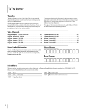
...carefully engineered to change product specifications, designs and equipment without notice and without incurring obligation. Please be added to the table below for purchasing a Cub Cadet Tiller. Please refer to the part number (e.g. 783-XXXXX-0637). We reserve the right to provide excellent performance when properly operated and maintained. You ...(LH) are observed from the operating position. To The Owner Thank You Thank you for current color codes: 0637 4021 0499 Black Yellow (Cub Cadet) Beige (Cub Cadet) 0685 Blue (Cub Cadet) 0691 Black Jack (Cub Cadet Commercial) 2
...carefully engineered to change product specifications, designs and equipment without notice and without incurring obligation. Please be added to the table below for purchasing a Cub Cadet Tiller. Please refer to the part number (e.g. 783-XXXXX-0637). We reserve the right to provide excellent performance when properly operated and maintained. You ...(LH) are observed from the operating position. To The Owner Thank You Thank you for current color codes: 0637 4021 0499 Black Yellow (Cub Cadet) Beige (Cub Cadet) 0685 Blue (Cub Cadet) 0691 Black Jack (Cub Cadet Commercial) 2
Parts Manual
Page 11
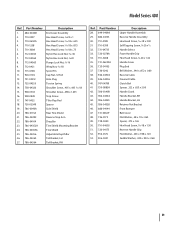
...-0533 16. 938-0849 17. 747-0432 18. 750-05349 19.. 786-0090A 20. 786-0113A 21. 786-04092 22. 786-04104 23. 786-04352A 24. 786-04355A 25. 786-04356 26. 786-04363 27. 786-04364 Description End Cover Assembly Hex Head Screw, 1⁄4-20 x 1 Hex Head Screw, 5⁄16...;16-18 Spirol Pin Cap Nut, 1⁄4 Rod Hole Plug Torsion Spring Shoulder Screw, .405 x .435 5⁄16-18 Shoulder Screw, .498 x 1.635 Stop Screw Tiller Flap Rod Spacer Side Shield Rear Tine Shield Reverse Stop Arm Drag Bar Tine Shield Mounting Bracket Tine Shield Adjustable Depth Bar Tail Bracket, LH...
...-0533 16. 938-0849 17. 747-0432 18. 750-05349 19.. 786-0090A 20. 786-0113A 21. 786-04092 22. 786-04104 23. 786-04352A 24. 786-04355A 25. 786-04356 26. 786-04363 27. 786-04364 Description End Cover Assembly Hex Head Screw, 1⁄4-20 x 1 Hex Head Screw, 5⁄16...;16-18 Spirol Pin Cap Nut, 1⁄4 Rod Hole Plug Torsion Spring Shoulder Screw, .405 x .435 5⁄16-18 Shoulder Screw, .498 x 1.635 Stop Screw Tiller Flap Rod Spacer Side Shield Rear Tine Shield Reverse Stop Arm Drag Bar Tine Shield Mounting Bracket Tine Shield Adjustable Depth Bar Tail Bracket, LH...
Parts Manual
Page 15
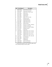
... Series 400 Ref. Part Number Description 918-04815A 1. 919-04184A Transmission Assembly Housing, Transmission 2. 710-3008 Hex Screw, 5/16-18, .75, Gr5 3. 911-04844 Shaft, Tiller 4. 911-04854 Shaft, Wheel 5. 911-05028 6. 714-04059 Shaft, Worm Key, Hi Pro .25 x 1.062 7. 716-0204 Retaining Ring 8. 716-04102 Retaining Ring, Int 9. 917...
... Series 400 Ref. Part Number Description 918-04815A 1. 919-04184A Transmission Assembly Housing, Transmission 2. 710-3008 Hex Screw, 5/16-18, .75, Gr5 3. 911-04844 Shaft, Tiller 4. 911-04854 Shaft, Wheel 5. 911-05028 6. 714-04059 Shaft, Worm Key, Hi Pro .25 x 1.062 7. 716-0204 Retaining Ring 8. 716-04102 Retaining Ring, Int 9. 917...


