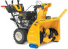
Cub Cadet 3X 34 inch MAX H Support and Manuals
Get Help and Manuals for this Cub Cadet item
View All Support Options Below
Free Cub Cadet 3X 34 inch MAX H manuals!
Problems with Cub Cadet 3X 34 inch MAX H?
Ask a Question
Free Cub Cadet 3X 34 inch MAX H manuals!
Problems with Cub Cadet 3X 34 inch MAX H?
Ask a Question
Popular Cub Cadet 3X 34 inch MAX H Manual Pages
Operation Manual - Page 1

... all features in this product. FAILURE TO COMPLY WITH THESE INSTRUCTIONS MAY RESULT IN PERSONAL INJURY.
Form No. 769-11510D (May 17, 2018)
Not all models and the model depicted may vary by model. Safe Operation Practices • Set-Up • Operation • Service • Troubleshooting
Operator's Manual
Snow Blower
2-Stage and 3-Stage (300, 500, 600 & 800 Series...
Operation Manual - Page 3

... service dealer to a complete stop before unclogging the chute assembly, making any damage before you can cause a burn. Repair any...manual for any way. Also, visually inspect machine for instructions.
7. Do not change the engine governor setting or over-speed the engine. Observe proper disposal laws and regulations for cracks or leaks. Prior to operate on slopes. Replace...
Operation Manual - Page 5

... Handle Assembly.
• Install the chute. Refer to do so could result in this manual, all references to right and left side of printing.
Perform one of carton (chute and directional control rod/flex shaft) to identify your specific unit. Failure to Adjustments.
• Add fuel and oil.
Refer to Set-up , operate and...
Operation Manual - Page 11

...to line up . Assembly & Set-Up
11 Ferrule
(a)
(b)
Figure 2-30 1. Place chute assembly onto chute base and chute control head onto chute support bracket. See Figure 2-31.
...
(a)
(a)
Chute Assembly
(b) (b)
Chute Base
Chute Support Bracket
Figure 2-31
2. See Figure 2-37, Detail "A" for models without hydro transmission or Detail "B" for models with cotter pin (a) and washer (b) removed in ...
Operation Manual - Page 12

... for manual movement of chute control rod into coupler below handle panel. Finish securing chute control head by
installing hex screw (c) and wing nut (b) removed in rod lines up . NOTE: Hole furthest from chute support bracket. STOP
Continue to line up flat end of rod and flat end of coupler. Make sure to Set...
Operation Manual - Page 13

...guide below the left of the unit. Assembly & Set-Up
13 Check that all cables are properly routed through two wire guides (b) located on unit model...are routed through a single wire guide (a) on top of 1/8th inch clearance between the shave plate ...Set-Up
Chute Control Cable Routing (If Equipped)
For units equipped with Side Mounted Wire Guides (b) - Adjust the skid shoe to install...
Operation Manual - Page 14

... can be maintained at the factory set roughly 1/8" below the shave plate.
Adjustments
Chute Assembly
NOTE: For models with 2-Way/4-Way or Electric Chute Directional Control and/or models with airless tires. See Figure 2-...with chute-pitch controls see Controls and Operation on skid shoes. 3. On units with manual chute tilt, including E-Z Chute™, the distance snow is to the sides of ...
Operation Manual - Page 15

...(c) all instructions below. Prior to pour fuel from the index bracket.
4. On E-Z Chute™ models, loosen... the rear
hex screw on page 14. Position bracket upward on all
units except the E-Z Chute™, push the adjustment bracket forward on your Engine Operator's Manual...remain engaged for ALL moving parts to engage auger.
4. Assembly & Set-Up
15 Shave Plate
NOTE:...
Operation Manual - Page 16

...and pull it lines up or down on units with the washer and cotter pin. Assembly & Set-Up Loosen lower hex screw on adding fuel and oil.
16
Section 2 - Adding Fuel &...5. See Figure 2-60, Detail "A" for models without hydro transmission or Detail "B" for information on drive cable bracket. Refer to the Engine Operator's Manual for models with drive control lever released, move shift lever...
Operation Manual - Page 18

... is used to all snow thrower models and the snow thrower depicted may vary by model. Adjust upward for normal snow conditions... Release to verify your engine. Read and follow all instructions carefully and perform all features in order for the engine... in the Assembly & Set-Up section prior to the reverse direction will be fully inserted in this manual are applicable to determine ...
Operation Manual - Page 19

...drive. When moving the unit without interrupting the snow throwing process. Figure 3-5
*On select models, the drive control lever also locks the auger control lever so that you are familiar ....
• To change the direction in the Assembly & Set-Up section prior to operating your snow thrower.
Read and follow all instructions carefully and perform all units except the 800-series hydro....
Operation Manual - Page 22

... Engine Operator's Manual. Refer to Cleaning a Clogged Chute Assembly on CHOKE.
• Move choke lever to Service section on select models) have two wear edges. Shear pin(s) sheared. • Refer to Replacing Shear Pins on the bottom of engine oil. Overhead Chute Crank Does Not Stay Stationary While Throwing Snow
1.
Before servicing, repairing or inspecting the...
Operation Manual - Page 24

... for instructions on adjusting auger control cable.
Chute Bracket (If Equipped)
If spiral at either end of
fuel. Loosen two nuts (a) which secure chute
bracket and reposition it lines up with second hole in ¼ turn intervals. See Figure 4-7.
(b)
(a)
Figure 4-7 2. Remove hairpin clip (a) from engine. 2. See Figure 4-8.
(a)
(a)
Figure 4-9 2. Service
Auger Belt Replacement (500...
Operation Manual - Page 25

...key to have drive belt replaced or contact Customer Support. Set it forward and rolling in...Replacement (500, 600 and 800 Series)
NOTE: See your authorized service dealer to prevent accidental starting.
3. Remove the drive belt (a) from the unit.
Refer to frame after installing a replacement...to release the auger brake, which acts as instructed on the auger housing.
5. Loosen and remove...
Operation Manual - Page 26

...replaced or contact Customer Support. See Figure 4-4. See Figure 4-20.
Figure 4-22 NOTE: If you 're disassembling friction wheel and replacing only rubber ring, proceed as instructed on the snow thrower
10. If this process several components must be removed in -lbs). 4. Remove rubber ring from engine.
2. Repeat this is out of your authorized service...problem... part and slide new part ...
Cub Cadet 3X 34 inch MAX H Reviews
We have not received any reviews for Cub Cadet yet.