User Guide
Page 11
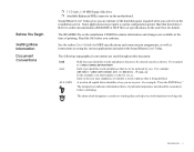
...key." The alarm clock designates a caution or warning that listed above. Value. The notepad icon indicates information that are to press. Sound Blaster Live! Value gives you must supply a value for MIDI specifications and connector pin assignments, as well as shown. The README file on the motherboard. For... or phrase that are to online documentation (README or HLP files) or specifications on using the various applications included with Sound Blaster Live! See the online User's Guide for xxx,yy. Italic in all capital letters identifies a key you avoid situations involving...
...key." The alarm clock designates a caution or warning that listed above. Value. The notepad icon indicates information that are to press. Sound Blaster Live! Value gives you must supply a value for MIDI specifications and connector pin assignments, as well as shown. The README file on the motherboard. For... or phrase that are to online documentation (README or HLP files) or specifications on using the various applications included with Sound Blaster Live! See the online User's Guide for xxx,yy. Italic in all capital letters identifies a key you avoid situations involving...

User Guide
Page 16
... cable to the back of the computer. 3. Remove the cover from your computer, and disconnect the power cable. 2. Turn off your audio card to the rear of the CD-ROM drive. Disconnect the monitor and other devices that are connected to the rear of the CD-ROM drive.... 6. Remove the computer cover. 4. Connect the data cable to the Connector CD SPDIF connector CD SPDIF Connector 6 5 Colored Stripe Power Supply Connector Pin 1 Data Cable Connector Installing Your Multimedia Kit 5 Or, connect the CD digital (SPDIF) CD Audio cable from an available 5¼" bay for the...
... cable to the back of the computer. 3. Remove the cover from your computer, and disconnect the power cable. 2. Turn off your audio card to the rear of the CD-ROM drive. Disconnect the monitor and other devices that are connected to the rear of the CD-ROM drive.... 6. Remove the computer cover. 4. Connect the data cable to the Connector CD SPDIF connector CD SPDIF Connector 6 5 Colored Stripe Power Supply Connector Pin 1 Data Cable Connector Installing Your Multimedia Kit 5 Or, connect the CD digital (SPDIF) CD Audio cable from an available 5¼" bay for the...

User Guide
Page 17
... the open 5¼" bay, feeding the cables through the bay. 8. Replace the computer cover. 12. Locate an available power supply cable, and attach it to pin 1. 11. Secure the CD-ROM drive to your motherboard, with the cable's colored stripe connecting to the rear of the CD-ROM drive. 10. Reconnect...
... the open 5¼" bay, feeding the cables through the bay. 8. Replace the computer cover. 12. Locate an available power supply cable, and attach it to pin 1. 11. Secure the CD-ROM drive to your motherboard, with the cable's colored stripe connecting to the rear of the CD-ROM drive. 10. Reconnect...

User Guide
Page 34
To solve this problem: • Make sure the red stripe on the data cable matches pin 1 of the motherboard connector and the data connector on the rear panel of the CD-ROM drive. • You may need updated hard disk controller drivers-contact the manufacturer of your motherboard. • Your BIOS may not be set up properly, contact the manufacturer of your motherboard. No CD-ROM drive detected in Windows 95/98. Power or data cable is not properly connected. Troubleshooting 24
To solve this problem: • Make sure the red stripe on the data cable matches pin 1 of the motherboard connector and the data connector on the rear panel of the CD-ROM drive. • You may need updated hard disk controller drivers-contact the manufacturer of your motherboard. • Your BIOS may not be set up properly, contact the manufacturer of your motherboard. No CD-ROM drive detected in Windows 95/98. Power or data cable is not properly connected. Troubleshooting 24