
Owners Manual
Page 1
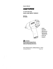
Owner's Manual CRAFTSMIIN" 1/2" Drive Ultra-Duty PISTOL GRIP IMPACT WRENCH Model No. 235.199050 _WARNING: Before using this Impact Wrench read this manual and follow all its Safety and Operating Instructions. • Safety ° Operation ° Maintenance ° Service and Adjustments = Parts List • Espa_oi Sears, Roebuck and Co., Hoffman Estates, IL 60179 Owner'= M=nual P7360 (1-98) Printed In USA
Owner's Manual CRAFTSMIIN" 1/2" Drive Ultra-Duty PISTOL GRIP IMPACT WRENCH Model No. 235.199050 _WARNING: Before using this Impact Wrench read this manual and follow all its Safety and Operating Instructions. • Safety ° Operation ° Maintenance ° Service and Adjustments = Parts List • Espa_oi Sears, Roebuck and Co., Hoffman Estates, IL 60179 Owner'= M=nual P7360 (1-98) Printed In USA
Owners Manual
Page 2
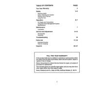
... Two Year Warranty Safety Warning Labels Notice, Warning and Caution Placing Tool In Service Using the Tool Operation Air Supply and Connections Using the Power Management System Specifications Maintenance Lubrication Service and Adjustment Disassembly Assembly Troubleshooting Parts List Exploded Drawing Parts for Ordering EspaSol PAGE 2 3-5 6-7 8-15 16 17-19 20-37 FULL TWO YEAR WARRANTY If this product to a Sears Service Center for replacement. Sears, Roebuck and Co., Dept. 817WA, Hoffman Estates, IL 60179...
... Two Year Warranty Safety Warning Labels Notice, Warning and Caution Placing Tool In Service Using the Tool Operation Air Supply and Connections Using the Power Management System Specifications Maintenance Lubrication Service and Adjustment Disassembly Assembly Troubleshooting Parts List Exploded Drawing Parts for Ordering EspaSol PAGE 2 3-5 6-7 8-15 16 17-19 20-37 FULL TWO YEAR WARRANTY If this product to a Sears Service Center for replacement. Sears, Roebuck and Co., Dept. 817WA, Hoffman Estates, IL 60179...

Owners Manual
Page 3
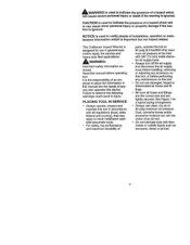
... Always turn off the air supply and disconnect the air supply hose before installing, removing or adjusting any accessory on this tool. ,_WARNING Air powered tools can vibrate in use damaged, frayed or deteriorated air hoses and fittings, _WARNING Always wear hearing protection when operating this tool. Keep body stance balanced and firm. Vibration, repetitive motions or uncomfortable positions may be harmful to your hands and arms. Stop using any maintenance...
... Always turn off the air supply and disconnect the air supply hose before installing, removing or adjusting any accessory on this tool. ,_WARNING Air powered tools can vibrate in use damaged, frayed or deteriorated air hoses and fittings, _WARNING Always wear hearing protection when operating this tool. Keep body stance balanced and firm. Vibration, repetitive motions or uncomfortable positions may be harmful to your hands and arms. Stop using any maintenance...
Owners Manual
Page 4
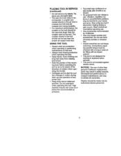
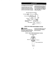
This Craftsman Impact Wrench is designed for a typical piping arrangement. ° Always use clean, dry air at the inlet with 3/8" (10 mm) inside diameter air supply hose. ° Always turn offthe air supply and disconnect the air supply hose before installing, removing or adjusting any maintenance on this tool, or before operating tool. It is the responsibility of an employer to hand-held/hand-operated pneumatic tools. • For safety, top performance, and maximum...
This Craftsman Impact Wrench is designed for a typical piping arrangement. ° Always use clean, dry air at the inlet with 3/8" (10 mm) inside diameter air supply hose. ° Always turn offthe air supply and disconnect the air supply hose before installing, removing or adjusting any maintenance on this tool, or before operating tool. It is the responsibility of an employer to hand-held/hand-operated pneumatic tools. • For safety, top performance, and maximum...
Owners Manual
Page 5
... only by Craftsman. • Use only impact sockets and accessories. Connections requiring specific torque must be alert for working in safety hazards, decreased tool performance, increased maintenance, and may invalidate all warranties. A couplerconnected directlyto the air inletincreases tool bulkand de- Do not overreach when operating this tool. • Keep hands, loose clothing and long hair away from rotating end of tool. • Note the position of a hose whip...
... only by Craftsman. • Use only impact sockets and accessories. Connections requiring specific torque must be alert for working in safety hazards, decreased tool performance, increased maintenance, and may invalidate all warranties. A couplerconnected directlyto the air inletincreases tool bulkand de- Do not overreach when operating this tool. • Keep hands, loose clothing and long hair away from rotating end of tool. • Note the position of a hose whip...
Owners Manual
Page 6
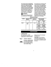
... hoses and fittingsare the correct size and are not torque controt devices. Dust, corrosivefumes and/or excessive moisture can greatly increase the life of an air tool. An air line filter can ruin the motor of an air tool. See Figure 1 for a typical pipingarrangement. Fastenerswith specific torque requirements must be checked with suitabletorque measuringdevices after installation with an air wrench. MODEL 19905 POWER MANAGEMENT SYSTEM Power settingindicators Minimum Maximum Power...
... hoses and fittingsare the correct size and are not torque controt devices. Dust, corrosivefumes and/or excessive moisture can greatly increase the life of an air tool. An air line filter can ruin the motor of an air tool. See Figure 1 for a typical pipingarrangement. Fastenerswith specific torque requirements must be checked with suitabletorque measuringdevices after installation with an air wrench. MODEL 19905 POWER MANAGEMENT SYSTEM Power settingindicators Minimum Maximum Power...
Owners Manual
Page 7
... max,) LUBRICATION Use Craftsman No. 18830 Pneumatic Tool Care Kit or a good quality SAE 20 or 20W motor oil. Air supply systems which do not deliver adequate air pressure can be further reduced in forward or reverse by AWARNING: The four power setting indicators of increasing size on this tool with these tools. SPECIFICATIONS Model 19905 Type of the impact mechanism through maximum power output in the reverse direction, no matter...
... max,) LUBRICATION Use Craftsman No. 18830 Pneumatic Tool Care Kit or a good quality SAE 20 or 20W motor oil. Air supply systems which do not deliver adequate air pressure can be further reduced in forward or reverse by AWARNING: The four power setting indicators of increasing size on this tool with these tools. SPECIFICATIONS Model 19905 Type of the impact mechanism through maximum power output in the reverse direction, no matter...
Owners Manual
Page 8
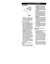
... bottom hammer "Bt" with the square driver positioned horizontally. Do not disassemble the tool any further than necessary to drop the two Hammer Pins (13). Disassembly of the Hammer Case. Set the mechanism, driver end up solid. DISASSEMBLY NOTICE: Numbers in parentheses in a vise, always use leather-covered vise jaws when clamping the handle in a vise with a plastic hammer, lift off the Hammer Case (15) and Hammer Case Gasket...
... bottom hammer "Bt" with the square driver positioned horizontally. Do not disassemble the tool any further than necessary to drop the two Hammer Pins (13). Disassembly of the Hammer Case. Set the mechanism, driver end up solid. DISASSEMBLY NOTICE: Numbers in parentheses in a vise, always use leather-covered vise jaws when clamping the handle in a vise with a plastic hammer, lift off the Hammer Case (15) and Hammer Case Gasket...

Owners Manual
Page 9
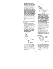
... the Motor Assembly is free. 2. Hold the Hammer Frame firmly and without disturbing the hammers, gently lift the Anvil while simultaneously rotating it needs to drop the Cylinder since it can now be replaced. 3. With the Anvil removed, lift out the two Hammer Pins. splined end of a turn from the Rotor if they need to the Cylinder, do this; Using the other hand, tap...
... the Motor Assembly is free. 2. Hold the Hammer Frame firmly and without disturbing the hammers, gently lift the Anvil while simultaneously rotating it needs to drop the Cylinder since it can now be replaced. 3. With the Anvil removed, lift out the two Hammer Pins. splined end of a turn from the Rotor if they need to the Cylinder, do this; Using the other hand, tap...

Owners Manual
Page 10
..., remove the Tilt Valve Seat Retainer (31) and Tilt Valve Seat Support (30). Press in both sides) Figure 7 3. Working from the Inlet Bushing unless it will allow the Inlet Bushing to remove the Tilt Valve Seat (29) from the front of the Cylinder. Use a hooked tool with no sharp edges to come free from the Handle of the Housing, push out the Motor...
..., remove the Tilt Valve Seat Retainer (31) and Tilt Valve Seat Support (30). Press in both sides) Figure 7 3. Working from the Inlet Bushing unless it will allow the Inlet Bushing to remove the Tilt Valve Seat (29) from the front of the Cylinder. Use a hooked tool with no sharp edges to come free from the Handle of the Housing, push out the Motor...

Owners Manual
Page 11
... above procedure for re- If the Reverse Valve does not come free, tap the bottom of the handle lightly with a thin film of oil before installation. 11 NOTICE: Always use leather-covered vise jaws to disengage the detent so that the Button can only be removed without first removing the Forward and Reverse Buttons (39) and (40). Notice the notches on...
... above procedure for re- If the Reverse Valve does not come free, tap the bottom of the handle lightly with a thin film of oil before installation. 11 NOTICE: Always use leather-covered vise jaws to disengage the detent so that the Button can only be removed without first removing the Forward and Reverse Buttons (39) and (40). Notice the notches on...
Owners Manual
Page 12
... throughthe Hammer Case Grease Fitting(17). When disassemblingand assemblingthe impact mechanism, remove all O-rings beforefinal assembly. Assembly of the motor bore in the Housing (19). Insert the Reverse Valve in their proper positions on the Re- Dowel Figure12 NOTICE: If the Reverse Valve is flush with Craftsman No. 18830 Grease. 3. If the Reverse Valve must be pushed back down through the handle until...
... throughthe Hammer Case Grease Fitting(17). When disassemblingand assemblingthe impact mechanism, remove all O-rings beforefinal assembly. Assembly of the motor bore in the Housing (19). Insert the Reverse Valve in their proper positions on the Re- Dowel Figure12 NOTICE: If the Reverse Valve is flush with Craftsman No. 18830 Grease. 3. If the Reverse Valve must be pushed back down through the handle until...
Owners Manual
Page 13
... from the rear. Assembly of Throttle Mechanism , Using an Inlet Bushing Screen Installation Tool, install the Inlet Bushing Screen (23), screened end first, in the front of the Inlet Bushing (22). When one Button has been installed, push the Button in either direction until an ear comes up against the Trigger. 6. Inlet Bushing Screen installation Tool Reverse /, Insert the Trigger Assembly in the bottom (hex...
... from the rear. Assembly of Throttle Mechanism , Using an Inlet Bushing Screen Installation Tool, install the Inlet Bushing Screen (23), screened end first, in the front of the Inlet Bushing (22). When one Button has been installed, push the Button in either direction until an ear comes up against the Trigger. 6. Inlet Bushing Screen installation Tool Reverse /, Insert the Trigger Assembly in the bottom (hex...

Owners Manual
Page 14
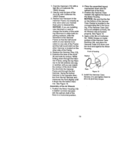
..., the Trigger will be installed. See Figure 17. ..i-....... 7 /" -... Assembly of the Cylinder. Failureto do so could resultin injury.Install the Tilt Valve Seat Retainer. Install the Motor Gasket in the Cylinder and secure with the Hammer Case installed and properlysecured to check installationof the Tilt Valve Seat Retainer or Inlet BushingScreen unless the entire Inlet BushingAssembly is installedin the tool with the...
..., the Trigger will be installed. See Figure 17. ..i-....... 7 /" -... Assembly of the Cylinder. Failureto do so could resultin injury.Install the Tilt Valve Seat Retainer. Install the Motor Gasket in the Cylinder and secure with the Hammer Case installed and properlysecured to check installationof the Tilt Valve Seat Retainer or Inlet BushingScreen unless the entire Inlet BushingAssembly is installedin the tool with the...
Owners Manual
Page 15
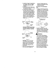
... on the other side of the Rotor in -lb (2.8 Nm) torque. 15 Assembly of the Rotor. 3. Install the Hammer Case Screws (11) and tighten them prior to 25 in a horizontal position. 2. Position the Hammer Case Gasket (18) against the Motor Housing. Apply a thin film of Craftsman No. 18830 Grease on the bottom of the Hammer Case Gasket is located on one way or another...
... on the other side of the Rotor in -lb (2.8 Nm) torque. 15 Assembly of the Rotor. 3. Install the Hammer Case Screws (11) and tighten them prior to 25 in a horizontal position. 2. Position the Hammer Case Gasket (18) against the Motor Housing. Apply a thin film of Craftsman No. 18830 Grease on the bottom of the Hammer Case Gasket is located on one way or another...
Owners Manual
Page 16
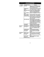
... broken parts. Damaged Reverse Valve Replace Reverse Valve. Refer to Figure 1 on Page 5. sembled correctly. 16 Refer to Assembly of the Motor. Remove Hammer Case Assembly and examine impact mechanism parts. Trouble Low power Motor will not run Tool will not impact Probable Cause Solution Dry Motor Daily, inject 3 cc of Craftsman No. 18830 Oil into Inlet and run the tool to lubricate the motor. Replace End Plates if they are scored. Assemble the Tool and...
... broken parts. Damaged Reverse Valve Replace Reverse Valve. Refer to Figure 1 on Page 5. sembled correctly. 16 Refer to Assembly of the Motor. Remove Hammer Case Assembly and examine impact mechanism parts. Trouble Low power Motor will not run Tool will not impact Probable Cause Solution Dry Motor Daily, inject 3 cc of Craftsman No. 18830 Oil into Inlet and run the tool to lubricate the motor. Replace End Plates if they are scored. Assemble the Tool and...
Owners Manual
Page 18
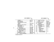
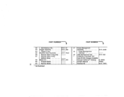
DOF9-879 2131-36 19 Housing Assembly .......... PART NUMBER'-'---_ + ...& CO + + 1 C_,linder 2 Front End Plate 3 Rotor Bearing (2 4 Vane Packet (set of 6 Vanes) (yellow 5 Rotor 6 Rear Rotor Bearing Retainer ......... 7 Motor Gasket 8 Anvil Assembly (1/2" square drive 9 Socket Retainer 10 Socket Retainer O-ring 11 Hammer Case Screw (4 Hammer Frame Assembly ........... 12 Hammer Frame 13 Hammer Frame Pin (2 14 Hammer(2 15 Hammer Case Assembly 16 Hammer Case Bushing .......... + included in Hammer Kit. 2131-3A 2131-11 2131-97 2131-42A...
DOF9-879 2131-36 19 Housing Assembly .......... PART NUMBER'-'---_ + ...& CO + + 1 C_,linder 2 Front End Plate 3 Rotor Bearing (2 4 Vane Packet (set of 6 Vanes) (yellow 5 Rotor 6 Rear Rotor Bearing Retainer ......... 7 Motor Gasket 8 Anvil Assembly (1/2" square drive 9 Socket Retainer 10 Socket Retainer O-ring 11 Hammer Case Screw (4 Hammer Frame Assembly ........... 12 Hammer Frame 13 Hammer Frame Pin (2 14 Hammer(2 15 Hammer Case Assembly 16 Hammer Case Bushing .......... + included in Hammer Kit. 2131-3A 2131-11 2131-97 2131-42A...
Owners Manual
Page 19
... Reverse Valve Assembly ..... 36 Reverse Valve O-ring (top) .. 37 Reverse Valve O-ring (bottom) (blue 38 Button Kit 39 Forward Button 40 Reverse Button * Not illustrated. 2131-57 2131 -A93 2131-A329 2131-K75 . Craftsman Pneumatic Tool 2131 -A249 2131-322 Care Kit (Oil, Grease) (Available through Craftsman ® Catalog) .. 9-18830 Owner's Manual P7350 _t Hammer Kit 2131-THK1 PART NUMBER--'-'_ 41 Power Management Assembly 42 Power Management Dial Seal 43 Inlet Clip Removal Tool .......
... Reverse Valve Assembly ..... 36 Reverse Valve O-ring (top) .. 37 Reverse Valve O-ring (bottom) (blue 38 Button Kit 39 Forward Button 40 Reverse Button * Not illustrated. 2131-57 2131 -A93 2131-A329 2131-K75 . Craftsman Pneumatic Tool 2131 -A249 2131-322 Care Kit (Oil, Grease) (Available through Craftsman ® Catalog) .. 9-18830 Owner's Manual P7350 _t Hammer Kit 2131-THK1 PART NUMBER--'-'_ 41 Power Management Assembly 42 Power Management Dial Seal 43 Inlet Clip Removal Tool .......

Owners Manual
Page 38
I BOO TOOL I-ILP 38 DO NOT DESTROY. NOTA: GUARDE ESTAS INSTRUCCIONES. NOTE: SAVE THESE INSTRUCTIONS. NO LAS DESTRUYA.
I BOO TOOL I-ILP 38 DO NOT DESTROY. NOTA: GUARDE ESTAS INSTRUCCIONES. NOTE: SAVE THESE INSTRUCTIONS. NO LAS DESTRUYA.

Owners Manual
Page 40
Forthe repairor replacemenpt adsyou need delivereddirectlyto yourhome Call7 am- 7 pro,7 daysa week 1-800-366-PART (1-800-366-7278) Paraordenarpeizasconentregaa domicilio- 1.-800--659-7084 For in-homemajorbrandrepairservice Call24 hoursa day,7 daysa week 1-800-4-REPAIR (1-800--.473-7247) Parapedirsan/Iciode reparaci6na domicilio- 1800-676-5811 Forthelocationofa Sears Partsand RepairCenterin yourarea Call24 hoursa day,7 daysa week 1-800-488...
Forthe repairor replacemenpt adsyou need delivereddirectlyto yourhome Call7 am- 7 pro,7 daysa week 1-800-366-PART (1-800-366-7278) Paraordenarpeizasconentregaa domicilio- 1.-800--659-7084 For in-homemajorbrandrepairservice Call24 hoursa day,7 daysa week 1-800-4-REPAIR (1-800--.473-7247) Parapedirsan/Iciode reparaci6na domicilio- 1800-676-5811 Forthelocationofa Sears Partsand RepairCenterin yourarea Call24 hoursa day,7 daysa week 1-800-488...


