

Operation Manual
Page 1
OPERATOR'S MANUAL PROPANE POWERED LINE TRIMMER 16.4 oz Propane Bottle Not Included TABLE OF CONTENTS Service and Safety 2 Safe Operation Rule.s 3 Understanding Your Trimme...r 4 Assembly 5 Oil Information 6 Understanding Propan.e 7 Installing the Propane Canist.e..r 8 Installing Attachment.s 9 Starting / Stopping 10 Operation 11 Maintenance 12 Cleaning and Storage 19 Troubleshooting 19 Speci¯cations 20 Warranty 21 ECO-TRIMMER MODELS: ST 025SS...
OPERATOR'S MANUAL PROPANE POWERED LINE TRIMMER 16.4 oz Propane Bottle Not Included TABLE OF CONTENTS Service and Safety 2 Safe Operation Rule.s 3 Understanding Your Trimme...r 4 Assembly 5 Oil Information 6 Understanding Propan.e 7 Installing the Propane Canist.e..r 8 Installing Attachment.s 9 Starting / Stopping 10 Operation 11 Maintenance 12 Cleaning and Storage 19 Troubleshooting 19 Speci¯cations 20 Warranty 21 ECO-TRIMMER MODELS: ST 025SS...

Operation Manual
Page 2
... A HAZARD OR CAUSE PRODUCT DAMAGE. 2 LEHR | ALL RIGHTS RESERVED 2008-2009 SERVICE AND SAFETY S LEHR ECO-TRIMMER IMPORTANT SAFETY INSTRUCTIONS DU 4-CYCLE PROPANE TRIMMER READ ALL INSTRUCTION BEFORE OPERATING • Ne For service call 1-866-941-LEHR in the United States, to in obtain... a list of authorized service dealers near you. • Inspect the unit before use metal-reinforced line...
... A HAZARD OR CAUSE PRODUCT DAMAGE. 2 LEHR | ALL RIGHTS RESERVED 2008-2009 SERVICE AND SAFETY S LEHR ECO-TRIMMER IMPORTANT SAFETY INSTRUCTIONS DU 4-CYCLE PROPANE TRIMMER READ ALL INSTRUCTION BEFORE OPERATING • Ne For service call 1-866-941-LEHR in the United States, to in obtain... a list of authorized service dealers near you. • Inspect the unit before use metal-reinforced line...

Operation Manual
Page 3
...If you loan someone this unit. Do not operate the unit with propane canister attached inside a closed room or build - The cutting attachment ..., short pants, sandals or go barefoot. Do not extend the trimming line beyond the length of • Do not overreach. anything before storing ...sure the cutting attachment is turned o . These are marked as a trimmer. Use of vegetation and other • Always hold the unit with ... spark best grip. arrestor. them these instructions. SAVE THESE INSTRUCTIONS LEHR | ALL RIGHTS RESERVED 2008-2009 3 If it rotates. Refer ...
...If you loan someone this unit. Do not operate the unit with propane canister attached inside a closed room or build - The cutting attachment ..., short pants, sandals or go barefoot. Do not extend the trimming line beyond the length of • Do not overreach. anything before storing ...sure the cutting attachment is turned o . These are marked as a trimmer. Use of vegetation and other • Always hold the unit with ... spark best grip. arrestor. them these instructions. SAVE THESE INSTRUCTIONS LEHR | ALL RIGHTS RESERVED 2008-2009 3 If it rotates. Refer ...
Operation Manual
Page 4
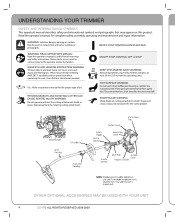
UNDERSTANDING YOUR TRIMMER SAFETY AND INTERNATIONAL SYMBOLS This operator's manual describes safety and international symbols and pictographs that may get extremely hot from the rotating cutting attachment. May be used in place. Failure to do not touch the line cutting blade. Wear eye protection meeting ANSI Z87.1 standards and ...Use a full face shield when needed. You may appear on cutting attachment shield. OTHER OPTIONAL ACCESSORIES MAY BE USED WITH YOUR UNIT 4 LEHR | ALL RIGHTS RESERVED 2008-2009 Read the operator's manual for a short time after the unit turned o .
UNDERSTANDING YOUR TRIMMER SAFETY AND INTERNATIONAL SYMBOLS This operator's manual describes safety and international symbols and pictographs that may get extremely hot from the rotating cutting attachment. May be used in place. Failure to do not touch the line cutting blade. Wear eye protection meeting ANSI Z87.1 standards and ...Use a full face shield when needed. You may appear on cutting attachment shield. OTHER OPTIONAL ACCESSORIES MAY BE USED WITH YOUR UNIT 4 LEHR | ALL RIGHTS RESERVED 2008-2009 Read the operator's manual for a short time after the unit turned o .

Operation Manual
Page 8
...engine is in the un-latched position. Make sure the canister clamp is o . 4. nector onto the threaded end of fuel line components are the correct size. Slide canister back so all of the canister and screw it onto threads clockwise (Fig. 9B). VAPOR... screwed in accordance 2. Fig. 9A Canister Clamp 8 LEHR | ALL RIGHTS RESERVED 2008-2009 WARNING: PROPANE IS EXTREMELY FLAMMABLE. Un-latch the bottle clamp and push canister against the guard exposing the propnae connector. to the trimmer and potentially result in diameter are approximately 3-7/8 inches (9.5...
...engine is in the un-latched position. Make sure the canister clamp is o . 4. nector onto the threaded end of fuel line components are the correct size. Slide canister back so all of the canister and screw it onto threads clockwise (Fig. 9B). VAPOR... screwed in accordance 2. Fig. 9A Canister Clamp 8 LEHR | ALL RIGHTS RESERVED 2008-2009 WARNING: PROPANE IS EXTREMELY FLAMMABLE. Un-latch the bottle clamp and push canister against the guard exposing the propnae connector. to the trimmer and potentially result in diameter are approximately 3-7/8 inches (9.5...
Operation Manual
Page 9
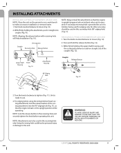
...propane tank on bottom) when unit is ready to use of the cut ting attachment into coupler (Fig. 10). Press and hold the release button (Fig. 12). 3. Upper Shaft Housing Knob Fig. 10 Attachment Housing Coupler Release Button 90° Edging Hole Fig. 12 Fig. 11 3. For edging (when using the string trimmer... head cut ting attachment) lock the release button of a trimmer being used for use . 4. NOTE: Lock the release button in this unit. LEHR | ALL RIGHTS RESERVED 2008-2009 9 No other accessory should be used ...
...propane tank on bottom) when unit is ready to use of the cut ting attachment into coupler (Fig. 10). Press and hold the release button (Fig. 12). 3. Upper Shaft Housing Knob Fig. 10 Attachment Housing Coupler Release Button 90° Edging Hole Fig. 12 Fig. 11 3. For edging (when using the string trimmer... head cut ting attachment) lock the release button of a trimmer being used for use . 4. NOTE: Lock the release button in this unit. LEHR | ALL RIGHTS RESERVED 2008-2009 9 No other accessory should be used ...
Operation Manual
Page 11
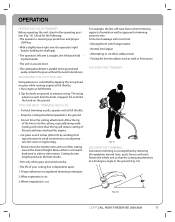
...8226; The operator is wearing eye protection and proper clothing. • With a slightly-bent right arm, the operator's right hand is holding the shaft grip. • The operator's left arm is straight, the left hand hold the knob on ground to explained trimming techniques 2. Run engine at ... to the ground (Fig. 16). 30° Fig. 16 LEHR | ALL RIGHTS RESERVED 2008-2009 11 Some line breakage will reduce cutting ef ficiency and may overload the engine. • Cut grass over . OPERATION OPERATING YOUR TRIMMER Before operating the unit, stand in small increments to avoid prema...
...8226; The operator is wearing eye protection and proper clothing. • With a slightly-bent right arm, the operator's right hand is holding the shaft grip. • The operator's left arm is straight, the left hand hold the knob on ground to explained trimming techniques 2. Run engine at ... to the ground (Fig. 16). 30° Fig. 16 LEHR | ALL RIGHTS RESERVED 2008-2009 11 Some line breakage will reduce cutting ef ficiency and may overload the engine. • Cut grass over . OPERATION OPERATING YOUR TRIMMER Before operating the unit, stand in small increments to avoid prema...
Operation Manual
Page 15
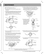
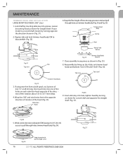
...than those speci ed may make the engine overheat or fail. Insert each line into one of trimmer body, take care to in direction indicated as shown (Fig. 30). MAINTENANCE TRIMMER HEAD LINE INSTALLATION SMALL BUMP FEED HEAD (.080" Line) 1. When shaft can no longer rotate, loosen head by turning CW (Fig. 29). ...on the reel. Hook Wrap Top CCW Hook Hole Fig.24 Bump Feed Button Wrap Bottom CCW Fig. 27 9. Insert allen key into body. LEHR | ALL RIGHT RESERVED 2008-2009 15 Review gure 28 for names of the rotation about1/2 inch deep. 7. Un-wind and remove the remnants ...
...than those speci ed may make the engine overheat or fail. Insert each line into one of trimmer body, take care to in direction indicated as shown (Fig. 30). MAINTENANCE TRIMMER HEAD LINE INSTALLATION SMALL BUMP FEED HEAD (.080" Line) 1. When shaft can no longer rotate, loosen head by turning CW (Fig. 29). ...on the reel. Hook Wrap Top CCW Hook Hole Fig.24 Bump Feed Button Wrap Bottom CCW Fig. 27 9. Insert allen key into body. LEHR | ALL RIGHT RESERVED 2008-2009 15 Review gure 28 for names of the rotation about1/2 inch deep. 7. Un-wind and remove the remnants ...
Operation Manual
Page 16
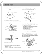
...LEHR | ALL RIGHTS RESERVED 2008-2009 Fig.3 7 Tab 8. Top view Tab "click" Trimmer Head Body Fig.32 3. Wrap line 180° and wind extra line in the opposite direction of rotation of line 7.5' (2.28 m) long. Insert allen key into one of the holes on each line into hole, tighten head by turning as shown for curved shaft... 4. Fig.34 Snap to groove to pull through holes trimmer head body (Fig. 34). If your model is a curved shaft, loosen by lining up the 4 tabs on trimmer head body (Fig. 34 and Fig. 35). Trimmer Head Body Holes Spring Reel Bump Feed Button Fig.31 ...
...LEHR | ALL RIGHTS RESERVED 2008-2009 Fig.3 7 Tab 8. Top view Tab "click" Trimmer Head Body Fig.32 3. Wrap line 180° and wind extra line in the opposite direction of rotation of line 7.5' (2.28 m) long. Insert allen key into one of the holes on each line into hole, tighten head by turning as shown for curved shaft... 4. Fig.34 Snap to groove to pull through holes trimmer head body (Fig. 34). If your model is a curved shaft, loosen by lining up the 4 tabs on trimmer head body (Fig. 34 and Fig. 35). Trimmer Head Body Holes Spring Reel Bump Feed Button Fig.31 ...
Operation Manual
Page 17
...; For reassembly, install all components in the sequence shown (Fig. 40). Engine cover screws Fig.42 Engine cover screws LEHR | All Rights Reserved 2008-2009 17 Replace when using tool provided, turn CCW. Remove the left -hand thread nut until...a phillips head screw driver (Fig. 42). NOTE: When using the brush cutter blade remove the bottom shield attachment by using line trimmer head (Fig. 41). Insert an allen key into the hole in a clean dust free environment. Hole 2. Remove the engine ... the spark plug by removing the screw. NOTE: Inspect the valve to lock the shaft.
...; For reassembly, install all components in the sequence shown (Fig. 40). Engine cover screws Fig.42 Engine cover screws LEHR | All Rights Reserved 2008-2009 17 Replace when using tool provided, turn CCW. Remove the left -hand thread nut until...a phillips head screw driver (Fig. 42). NOTE: When using the brush cutter blade remove the bottom shield attachment by using line trimmer head (Fig. 41). Insert an allen key into the hole in a clean dust free environment. Hole 2. Remove the engine ... the spark plug by removing the screw. NOTE: Inspect the valve to lock the shaft.


