Service Guide
Page 34
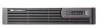
.... Refer to Chapter 3, "Illustrated Parts Catalog," to be caused by a temperature sensor and is displaced through the ventilation grill located on the left side of the notebook. The notebook uses an electric fan for disassembly steps. Product Description 1.4 Design Overview This... These conditions can be turned on automatically when high temperature conditions exist. The system board provides the following device connections: ■ Memory module ■ Mini PCI communications devices ■ Hard drive ■ Display ■ Keyboard and TouchPad ■ Audio ■...
.... Refer to Chapter 3, "Illustrated Parts Catalog," to be caused by a temperature sensor and is displaced through the ventilation grill located on the left side of the notebook. The notebook uses an electric fan for disassembly steps. Product Description 1.4 Design Overview This... These conditions can be turned on automatically when high temperature conditions exist. The system board provides the following device connections: ■ Memory module ■ Mini PCI communications devices ■ Hard drive ■ Display ■ Keyboard and TouchPad ■ Audio ■...
Service Guide
Page 110
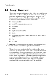
...determine the section number to remove heat sink Processor 0 Strip cover 3 Keyboard 4 Modem board 2 Mini PCI communications card 0 System memory module 0 (internal, located under keyboard) Maintenance and Service Guide 5-3 Section 5.3 5.4 5.5 5.6 5.7 5.8 5.9 5.10 5.11 5.12 5.13 Disassembly Sequence... Notebook feet 0 Memory module (external, 1 loosened located on bottom of notebook) Combination drive 2 to remove 4 to disassemble Heat sink 10 to remove Pavilion heat sink cover 11 to remove HP Compaq Business Notebook nx9100 Series and Compaq Presario R3000 heat sink cover...
...determine the section number to remove heat sink Processor 0 Strip cover 3 Keyboard 4 Modem board 2 Mini PCI communications card 0 System memory module 0 (internal, located under keyboard) Maintenance and Service Guide 5-3 Section 5.3 5.4 5.5 5.6 5.7 5.8 5.9 5.10 5.11 5.12 5.13 Disassembly Sequence... Notebook feet 0 Memory module (external, 1 loosened located on bottom of notebook) Combination drive 2 to remove 4 to disassemble Heat sink 10 to remove Pavilion heat sink cover 11 to remove HP Compaq Business Notebook nx9100 Series and Compaq Presario R3000 heat sink cover...

Service Guide
Page 229
Screw Listing Table C-1 Phillips M2.5×6.0 Screw Head mm Color Qty. Length Thread Width Black 46 6.0 mm 2.0 mm 4.0 mm Where used: 1 Two screws that secure the hard drive cover to the hard drive (documented in Section 5.3) 2 One screw that secures the memory module compartment cover to the notebook (documented in Section 5.5) 3 Two screws that secure the combination drive to the notebook (documented in Section 5.6) Phillips PM2.5×6.0 Screw Locations C-2 Maintenance and Service Guide
Screw Listing Table C-1 Phillips M2.5×6.0 Screw Head mm Color Qty. Length Thread Width Black 46 6.0 mm 2.0 mm 4.0 mm Where used: 1 Two screws that secure the hard drive cover to the hard drive (documented in Section 5.3) 2 One screw that secures the memory module compartment cover to the notebook (documented in Section 5.5) 3 Two screws that secure the combination drive to the notebook (documented in Section 5.6) Phillips PM2.5×6.0 Screw Locations C-2 Maintenance and Service Guide
Service Guide
Page 263
... illustrated 3-15, 3-17 spare part number 3-8, 3-18 1394 connector location 1-9, 1-13 pin assignments A-3 5-in-1 Memory Reader 1-17, 1-23 A AC adapter spare part number 3-32 specifications 6-18 AC power connector, location 1-15 arrow keys, location 1-19 audio board spare part number 3-4 audio troubleshooting 2-26 audio-in (microphone) jack location 1-9, 1-13 pin assignments A-6 audio-out (headphone) jack...
... illustrated 3-15, 3-17 spare part number 3-8, 3-18 1394 connector location 1-9, 1-13 pin assignments A-3 5-in-1 Memory Reader 1-17, 1-23 A AC adapter spare part number 3-32 specifications 6-18 AC power connector, location 1-15 arrow keys, location 1-19 audio board spare part number 3-4 audio troubleshooting 2-26 audio-in (microphone) jack location 1-9, 1-13 pin assignments A-6 audio-out (headphone) jack...

Service Guide
Page 267
... part number 3-10, 3-26, 3-30, 5-7 specifications 6-16 troubleshooting 2-21 Media button, location 1-21 memory module removal 5-11 spare part number 3-12, 3-26, 5-11, 5-37 memory module compartment cover illustrated 3-15, 3-17, 3-29 spare part number 3-8, 3-18, 3-29 memory module compartment, location 1-27 microphone jack location 1-9, 1-13 pin assignements A-6 Mini PCI communications card illustrated 3-19, 3-21, 3-23...
... part number 3-10, 3-26, 3-30, 5-7 specifications 6-16 troubleshooting 2-21 Media button, location 1-21 memory module removal 5-11 spare part number 3-12, 3-26, 5-11, 5-37 memory module compartment cover illustrated 3-15, 3-17, 3-29 spare part number 3-8, 3-18, 3-29 memory module compartment, location 1-27 microphone jack location 1-9, 1-13 pin assignements A-6 Mini PCI communications card illustrated 3-19, 3-21, 3-23...
Service Guide
Page 269
... RJ-11 (modem) jack location 1-15 pin assignments A-2 RJ-45 (network) jack location 1-9, 1-14 pin assignments A-1 S screw kit, spare part number 3-33 security cable slot, location 1-15 security card, spare part number 3-33 serial number 5-2 serial number location 3-2, 5-2 service considerations 4-2 slot location 1-17 spare part numbers 1394... 5-7 heat sink 3-10, 3-26, 5-21 heat sink cover 3-8 keyboard 3-6, 3-18, 5-32 label kit 3-32 LED board 3-4, 5-53 memory module 3-26, 5-11, 5-37 memory module compartment cover 3-8 Mini PCI communications card 3-20, 5-35 Maintenance and Service Guide Index-7
... RJ-11 (modem) jack location 1-15 pin assignments A-2 RJ-45 (network) jack location 1-9, 1-14 pin assignments A-1 S screw kit, spare part number 3-33 security cable slot, location 1-15 security card, spare part number 3-33 serial number 5-2 serial number location 3-2, 5-2 service considerations 4-2 slot location 1-17 spare part numbers 1394... 5-7 heat sink 3-10, 3-26, 5-21 heat sink cover 3-8 keyboard 3-6, 3-18, 5-32 label kit 3-32 LED board 3-4, 5-53 memory module 3-26, 5-11, 5-37 memory module compartment cover 3-8 Mini PCI communications card 3-20, 5-35 Maintenance and Service Guide Index-7