Service Guide
Page 41
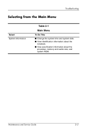
Maintenance and Service Guide 2-3 Selecting from the Main Menu Troubleshooting Select System Information Table 2-1 Main Menu To Do This ■ Change the system time and system date. ■ View identification information about the notebook. ■ View specification information about the processor, memory and cache size, and system ROM.
Maintenance and Service Guide 2-3 Selecting from the Main Menu Troubleshooting Select System Information Table 2-1 Main Menu To Do This ■ Change the system time and system date. ■ View identification information about the notebook. ■ View specification information about the processor, memory and cache size, and system ROM.

Service Guide
Page 76
refer to Appendix C, "Screw Listing," for more information on screw specifications and usage). 373294-001 ■ PM2.0×9.0 screw ■ PM2.0×8.0 screw ■ PM2.0×6.0 screw ■ PM2.0×5.0 screw ■ PM2.0×4.0 screw ■ ...
refer to Appendix C, "Screw Listing," for more information on screw specifications and usage). 373294-001 ■ PM2.0×9.0 screw ■ PM2.0×8.0 screw ■ PM2.0×6.0 screw ■ PM2.0×5.0 screw ■ PM2.0×4.0 screw ■ ...

Service Guide
Page 129
... provides physical and performance specifications. Table 6-1 Notebook Dimensions with 15.0-inch display Height Width Depth with 14.1-inch display Height Width Depth Weight (varies by configuration) with 15.0-inch display ...
... provides physical and performance specifications. Table 6-1 Notebook Dimensions with 15.0-inch display Height Width Depth with 14.1-inch display Height Width Depth Weight (varies by configuration) with 15.0-inch display ...

Service Guide
Page 130
The notebook operates well within this range of temperatures. 6-2 Maintenance and Service Guide Specifications Table 6-1 Notebook (Continued) Temperature Operating (not writing to optical disc) Operating (writing to optical disc) Nonoperating 0°C to 35°C 5°C to 35°C -20&#...
The notebook operates well within this range of temperatures. 6-2 Maintenance and Service Guide Specifications Table 6-1 Notebook (Continued) Temperature Operating (not writing to optical disc) Operating (writing to optical disc) Nonoperating 0°C to 35°C 5°C to 35°C -20&#...

Service Guide
Page 131
Specifications Table 6-2 15.0-inch, XGA, TFT Display Dimensions Height Width Diagonal Number of colors Contrast ratio Brightness Pixel resolution Pitch Format Configuration Backlight Character display Total power consumption Viewing angle 30.0 cm 22.9 cm 38.1 cm Up to 16.8 million 250:1 150 nits typical 11.8 in 9.0 in 15.0 in 0.264 × 0.264 mm 1024 × 768 RGB vertical stripe Edge lit 80 × 25 5.5 W +/-35° horizontal, +15/-35° vertical typical Maintenance and Service Guide 6-3
Specifications Table 6-2 15.0-inch, XGA, TFT Display Dimensions Height Width Diagonal Number of colors Contrast ratio Brightness Pixel resolution Pitch Format Configuration Backlight Character display Total power consumption Viewing angle 30.0 cm 22.9 cm 38.1 cm Up to 16.8 million 250:1 150 nits typical 11.8 in 9.0 in 15.0 in 0.264 × 0.264 mm 1024 × 768 RGB vertical stripe Edge lit 80 × 25 5.5 W +/-35° horizontal, +15/-35° vertical typical Maintenance and Service Guide 6-3

Service Guide
Page 132
Specifications Table 6-3 14.1-inch, XGA, TFT Display Dimensions Height Width Diagonal Number of colors Contrast ratio Brightness Pixel resolution Pitch Format Configuration Backlight Character display Total power consumption Viewing angle 28.5 cm 21.3 cm 35.8 cm up to 16.8 million 250:1 180 nits typical 11.2 in 8.4 in 14.1 in 0.279 × 0.279 mm 1024 × 768 RGB vertical stripe Edge lit 80 × 25 4 W +/-40° horizontal, +20/-40° vertical typical 6-4 Maintenance and Service Guide
Specifications Table 6-3 14.1-inch, XGA, TFT Display Dimensions Height Width Diagonal Number of colors Contrast ratio Brightness Pixel resolution Pitch Format Configuration Backlight Character display Total power consumption Viewing angle 28.5 cm 21.3 cm 35.8 cm up to 16.8 million 250:1 180 nits typical 11.2 in 8.4 in 14.1 in 0.279 × 0.279 mm 1024 × 768 RGB vertical stripe Edge lit 80 × 25 4 W +/-40° horizontal, +20/-40° vertical typical 6-4 Maintenance and Service Guide

Service Guide
Page 133
.... Consult Customer Care for details. *1 GB = 1 billion bytes when referring to 131°F) ✎ Certain restrictions and exclusions apply. Specifications Table 6-4 4200-rpm Hard Drives 60-GB 40-GB 30-GB User capacity per drive* 60 GB 40 GB 30 GB Dimensions Height Width...mm 70 mm 99 g 9.5 mm 70 mm 99 g Interface type ATA-5 ATA-5 ATA-5 Transfer rate Synchronous (maximum) Security 100 MB/sec ATA security 100 MB/sec ATA security 100 MB/sec ATA security Seek times (typical read, including setting) Single track Average Maximum Logical blocks† 3 ms 13 ms 24 ms...
.... Consult Customer Care for details. *1 GB = 1 billion bytes when referring to 131°F) ✎ Certain restrictions and exclusions apply. Specifications Table 6-4 4200-rpm Hard Drives 60-GB 40-GB 30-GB User capacity per drive* 60 GB 40 GB 30 GB Dimensions Height Width...mm 70 mm 99 g 9.5 mm 70 mm 99 g Interface type ATA-5 ATA-5 ATA-5 Transfer rate Synchronous (maximum) Security 100 MB/sec ATA security 100 MB/sec ATA security 100 MB/sec ATA security Seek times (typical read, including setting) Single track Average Maximum Logical blocks† 3 ms 13 ms 24 ms...

Service Guide
Page 134
Specifications Table 6-5 Primary 6-cell, Li-Ion Battery Pack Dimensions Height Width Depth Weight Energy Voltage Amp-hour capacity Watt-hour capacity Temperature Operating Nonoperating 2.00 cm 9.40 cm 13.40 cm .34 kg 11.1 V 4.4 Ah 48 Wh 5°C to 45°C 0°C to 60°C .79 in 3.70 in 5.28 in .75 lb 41°F to 113°F 32°F to 140°F 6-6 Maintenance and Service Guide
Specifications Table 6-5 Primary 6-cell, Li-Ion Battery Pack Dimensions Height Width Depth Weight Energy Voltage Amp-hour capacity Watt-hour capacity Temperature Operating Nonoperating 2.00 cm 9.40 cm 13.40 cm .34 kg 11.1 V 4.4 Ah 48 Wh 5°C to 45°C 0°C to 60°C .79 in 3.70 in 5.28 in .75 lb 41°F to 113°F 32°F to 140°F 6-6 Maintenance and Service Guide

Service Guide
Page 135
Specifications Table 6-6 Optional 8-cell, Li-Ion Battery Pack Dimensions Height Width Depth Weight Energy Voltage Amp-hour capacity Watt-hour capacity Temperature Operating Nonoperating 2.00 cm 9.40 cm 13.40 cm .34 kg 14.4 V 4.4 Ah 65 Wh 5°C to 45°C 0°C to 60°C .79 in 3.70 in 5.28 in .75 lb 41°F to 113°F 32°F to 140°F Maintenance and Service Guide 6-7
Specifications Table 6-6 Optional 8-cell, Li-Ion Battery Pack Dimensions Height Width Depth Weight Energy Voltage Amp-hour capacity Watt-hour capacity Temperature Operating Nonoperating 2.00 cm 9.40 cm 13.40 cm .34 kg 14.4 V 4.4 Ah 65 Wh 5°C to 45°C 0°C to 60°C .79 in 3.70 in 5.28 in .75 lb 41°F to 113°F 32°F to 140°F Maintenance and Service Guide 6-7

Service Guide
Page 137
Specifications Table 6-8 24X Max DVD/CD-RW Combo Drive Applicable disk Center hole diameter Disk diameter Standard disc Mini disc Disk thickness Track pitch Access time Random Full stroke Audio output level Cache buffer DVD-5, DVD-9, DVD-10 CD-ROM (Mode 1 and 2) CD Digital Audio CD-XA ready (Mode 2, Form 1 and 2) CD-I ready (Mode 2, Form 1 and 2) CD-R (read only) CD Plus Photo CD (single/multisession) CD-Bridge 1.5 cm 0.59 in 12 cm 8 cm 1.2 mm 0.74 µm 4.72 in 3.15 in 0.047 in < 150 ms < 225 ms Audio-out, 0.7 Vrms 128 KB/s Maintenance and Service Guide 6-9
Specifications Table 6-8 24X Max DVD/CD-RW Combo Drive Applicable disk Center hole diameter Disk diameter Standard disc Mini disc Disk thickness Track pitch Access time Random Full stroke Audio output level Cache buffer DVD-5, DVD-9, DVD-10 CD-ROM (Mode 1 and 2) CD Digital Audio CD-XA ready (Mode 2, Form 1 and 2) CD-I ready (Mode 2, Form 1 and 2) CD-R (read only) CD Plus Photo CD (single/multisession) CD-Bridge 1.5 cm 0.59 in 12 cm 8 cm 1.2 mm 0.74 µm 4.72 in 3.15 in 0.047 in < 150 ms < 225 ms Audio-out, 0.7 Vrms 128 KB/s Maintenance and Service Guide 6-9

Service Guide
Page 138
Specifications Table 6-8 24X Max DVD/CD-RW Combo Drive (Continued) Data transfer rate CD-R (24X) CD-RW (10X) CD-ROM (24X) DVD (8X) Multiword DMA mode 2 Startup time Stop time 3600 KB/s (150 KB/s at 1X CD rate) 1500 KB/s (150 KB/s at 1X CD rate) 3600 KB/s (150 KB/s at 1X CD rate) 10,800 KB/s (1352 KB/s at 1X DVD rate) 16.6 MB/s < 15 seconds < 6 seconds 6-10 Maintenance and Service Guide
Specifications Table 6-8 24X Max DVD/CD-RW Combo Drive (Continued) Data transfer rate CD-R (24X) CD-RW (10X) CD-ROM (24X) DVD (8X) Multiword DMA mode 2 Startup time Stop time 3600 KB/s (150 KB/s at 1X CD rate) 1500 KB/s (150 KB/s at 1X CD rate) 3600 KB/s (150 KB/s at 1X CD rate) 10,800 KB/s (1352 KB/s at 1X DVD rate) 16.6 MB/s < 15 seconds < 6 seconds 6-10 Maintenance and Service Guide

Service Guide
Page 139
Specifications Table 6-9 8X MAX DVD-ROM Drive Applicable disk Center hole diameter Disk diameter Standard disc Mini disc Disk thickness Track pitch Access time Random DVD ...
Specifications Table 6-9 8X MAX DVD-ROM Drive Applicable disk Center hole diameter Disk diameter Standard disc Mini disc Disk thickness Track pitch Access time Random DVD ...
Service Guide
Page 140
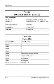
Specifications Table 6-9 8X MAX DVD-ROM Drive (Continued) Data transfer rate Max 24X CD Max 8X DVD 3600 KB/s (150 KB/s at 1X CD rate) 10,800 KB/s (1352 KB/s at 1X DVD rate) Multiword DMA mode 2 Startup time Stop time 16.6 MB/s < 10 seconds < 3 seconds Table 6-10 System DMA Hardware DMA System Function DMA0 n/a DMA1* n/a DMA2* n/a DMA3 n/a DMA4 Direct memory access controller DMA5* Available for PC Card DMA6 Not assigned DMA7 Not assigned *PC Card controller can use DMA 1, 2, or 5. 6-12 Maintenance and Service Guide
Specifications Table 6-9 8X MAX DVD-ROM Drive (Continued) Data transfer rate Max 24X CD Max 8X DVD 3600 KB/s (150 KB/s at 1X CD rate) 10,800 KB/s (1352 KB/s at 1X DVD rate) Multiword DMA mode 2 Startup time Stop time 16.6 MB/s < 10 seconds < 3 seconds Table 6-10 System DMA Hardware DMA System Function DMA0 n/a DMA1* n/a DMA2* n/a DMA3 n/a DMA4 Direct memory access controller DMA5* Available for PC Card DMA6 Not assigned DMA7 Not assigned *PC Card controller can use DMA 1, 2, or 5. 6-12 Maintenance and Service Guide

Service Guide
Page 142
audio possible configurations are IRQ5, IRQ7, IRQ9, IRQ10, or none. 6-14 Maintenance and Service Guide Specifications Table 6-11 System Interrupts (Continued) Hardware IRQ System Function IRQ11 Intel USB EHCI controller-24CD Intel USB UHCI controller-24C4 Intel USB UHCI controller-24C7 ...
audio possible configurations are IRQ5, IRQ7, IRQ9, IRQ10, or none. 6-14 Maintenance and Service Guide Specifications Table 6-11 System Interrupts (Continued) Hardware IRQ System Function IRQ11 Intel USB EHCI controller-24CD Intel USB UHCI controller-24C4 Intel USB UHCI controller-24C7 ...

Service Guide
Page 157
C Screw Listing This appendix provides specification and reference information for the screws used in the Miscellaneous Screw Kit, spare part number 373294-001. All screws listed in this appendix are available in the notebook. Maintenance and Service Guide C-1
C Screw Listing This appendix provides specification and reference information for the screws used in the Miscellaneous Screw Kit, spare part number 373294-001. All screws listed in this appendix are available in the notebook. Maintenance and Service Guide C-1
Service Guide
Page 177
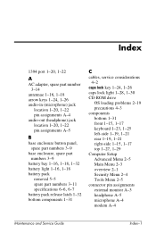
... location 1-20, 1-22 pin assignments A-5 B base enclosure button panel, spare part numbers 3-9 base enclosure, spare part numbers 3-9 battery bay 1-16, 1-18, 1-32 battery light 1-16, 1-18 battery pack removal 5-5 spare part numbers 3-11 specifications 6-6, 6-7 battery pack release latch 1-32 bottom components 1-31 C cables, service considerations 4-2 caps lock key 1-24, 1-26 caps lock light...
... location 1-20, 1-22 pin assignments A-5 B base enclosure button panel, spare part numbers 3-9 base enclosure, spare part numbers 3-9 battery bay 1-16, 1-18, 1-32 battery light 1-16, 1-18 battery pack removal 5-5 spare part numbers 3-11 specifications 6-6, 6-7 battery pack release latch 1-32 bottom components 1-31 C cables, service considerations 4-2 caps lock key 1-24, 1-26 caps lock light...
Service Guide
Page 178
... assembly removal 5-23 spare part numbers 3-3, 5-23 specifications 6-3, 6-4 display release button 1-16, 1-18 display screw covers, spare part number 3-3, 5-23 DMA specifications 6-12 drives, preventing damage 4-3 DVD+RW/R and CD-RW Combo Drive, specifications 6-8 DVD/CD-RW Combo Drive, specifications 6-9 DVD-ROM drive OS loading problems 2-19 precautions 4-3 specifications 6-11 E electrostatic discharge 4-4, 4-7 exhaust vents 1-...14 no OS loading from CD/DVD Drive 2-19 no OS loading from diskette drive 2-18 no OS loading from hard drive 2-15, 2-16, 2-17 Index-2 Maintenance and Service Guide
... assembly removal 5-23 spare part numbers 3-3, 5-23 specifications 6-3, 6-4 display release button 1-16, 1-18 display screw covers, spare part number 3-3, 5-23 DMA specifications 6-12 drives, preventing damage 4-3 DVD+RW/R and CD-RW Combo Drive, specifications 6-8 DVD/CD-RW Combo Drive, specifications 6-9 DVD-ROM drive OS loading problems 2-19 precautions 4-3 specifications 6-11 E electrostatic discharge 4-4, 4-7 exhaust vents 1-...14 no OS loading from CD/DVD Drive 2-19 no OS loading from diskette drive 2-18 no OS loading from hard drive 2-15, 2-16, 2-17 Index-2 Maintenance and Service Guide
Service Guide
Page 179
...equipment and methods 4-5 H hard drive OS loading problems 2-15 precautions 4-3 removal 5-6 spare part numbers 3-11, 3-13, 5-6 specifications 6-5 hard drive bay 1-16, 1-18, 1-32 hard drive cover, removal 5-6 hard drive guide, spare part number 3-7, 5-41 hard drive tray, spare part... 5-31 spare part number 3-5, 5-31 I I/O address specifications 6-15 IDE drive light 1-16, 1-18 infrared port 1-18 Integrated Drive Electronics light 1-16, 1-18 interrupt specifications 6-13 K keyboard removal 5-16 spare part numbers 3-5, 5-16 troubleshooting 2-22 keyboard components 1-23, 1-25 keyboard cover removal...
...equipment and methods 4-5 H hard drive OS loading problems 2-15 precautions 4-3 removal 5-6 spare part numbers 3-11, 3-13, 5-6 specifications 6-5 hard drive bay 1-16, 1-18, 1-32 hard drive cover, removal 5-6 hard drive guide, spare part number 3-7, 5-41 hard drive tray, spare part... 5-31 spare part number 3-5, 5-31 I I/O address specifications 6-15 IDE drive light 1-16, 1-18 infrared port 1-18 Integrated Drive Electronics light 1-16, 1-18 interrupt specifications 6-13 K keyboard removal 5-16 spare part numbers 3-5, 5-16 troubleshooting 2-22 keyboard components 1-23, 1-25 keyboard cover removal...
Service Guide
Page 180
... location 1-19, 1-21 pin assignments A-2 network, troubleshooting 2-24 nonfunctioning device, troubleshooting 2-21 notebook feet locations 5-9 spare part number 3-9, 5-9 notebook specifications 6-1 notebook, resetting 1-13 num lock key 1-24, 1-26 numeric lock light 1-28, 1-30 O One-Touch buttons 1-28, 1-30 operating ...system loading, troubleshooting 2-14 optical drive location 1-16, 1-18 OS loading problems 2-19 removal 5-22 spare part numbers 3-9, 3-13, 5-22 P packing precautions 4-4 parallel port location 1-21 pin...
... location 1-19, 1-21 pin assignments A-2 network, troubleshooting 2-24 nonfunctioning device, troubleshooting 2-21 notebook feet locations 5-9 spare part number 3-9, 5-9 notebook specifications 6-1 notebook, resetting 1-13 num lock key 1-24, 1-26 numeric lock light 1-28, 1-30 O One-Touch buttons 1-28, 1-30 operating ...system loading, troubleshooting 2-14 optical drive location 1-16, 1-18 OS loading problems 2-19 removal 5-22 spare part numbers 3-9, 3-13, 5-22 P packing precautions 4-4 parallel port location 1-21 pin...
Service Guide
Page 181
Index power cord, spare part numbers 3-14 power management features 1-14 power, troubleshooting 2-8 power/standby light 1-16, 1-18 processor removal 5-33 spare part numbers 3-7, 5-33 R rear components 1-19, 1-21 removal preliminaries 4-1 procedures 5-1 replacement preliminaries ... security cable slot 1-20, 1-22 serial number 3-1, 5-1 serial port location 1-21 pin assignments A-7 service considerations 4-2 speakers location 1-28, 1-30 removal 5-21 specifications battery pack 6-6, 6-7 display 6-3, 6-4 DMA 6-12 DVD+RW/R and CD-RW Combo Drive 6-8 DVD/CD-RW Combo Drive 6-9 DVD-ROM Drive 6-11 hard ...
Index power cord, spare part numbers 3-14 power management features 1-14 power, troubleshooting 2-8 power/standby light 1-16, 1-18 processor removal 5-33 spare part numbers 3-7, 5-33 R rear components 1-19, 1-21 removal preliminaries 4-1 procedures 5-1 replacement preliminaries ... security cable slot 1-20, 1-22 serial number 3-1, 5-1 serial port location 1-21 pin assignments A-7 service considerations 4-2 speakers location 1-28, 1-30 removal 5-21 specifications battery pack 6-6, 6-7 display 6-3, 6-4 DMA 6-12 DVD+RW/R and CD-RW Combo Drive 6-8 DVD/CD-RW Combo Drive 6-9 DVD-ROM Drive 6-11 hard ...
