
Service Guide
Page 4
... Serial Number 5-1 5.2 Disassembly Sequence Chart 5-2 5.3 Preparing the Notebook for Disassembly 5-4 5.4 Notebook Feet 5-9 5.5 Memory Module 5-10 5.6 Mini PCI Communications Board 5-12 5.7 Keyboard Cover 5-14 5.8 Keyboard 5-16 5.9 Switch Board 5-19 5.10 Speakers 5-21 5.11 Optical Drive 5-22 5.12 Display Assembly 5-23 5.13 ...Top Cover 5-27 5.14 Heat Sink 5-31 5.15 Processor 5-33 5.16 Wireless Button Board 5-35 5.17 Diskette Drive ...
... Serial Number 5-1 5.2 Disassembly Sequence Chart 5-2 5.3 Preparing the Notebook for Disassembly 5-4 5.4 Notebook Feet 5-9 5.5 Memory Module 5-10 5.6 Mini PCI Communications Board 5-12 5.7 Keyboard Cover 5-14 5.8 Keyboard 5-16 5.9 Switch Board 5-19 5.10 Speakers 5-21 5.11 Optical Drive 5-22 5.12 Display Assembly 5-23 5.13 ...Top Cover 5-27 5.14 Heat Sink 5-31 5.15 Processor 5-33 5.16 Wireless Button Board 5-35 5.17 Diskette Drive ...
Service Guide
Page 7
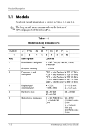
... Notebook PCs. Hnx9040 1 Key 1 2 3 4 5 6 Table 1-1 Model Naming Conventions Key U P735 X5 60 Y Cc 51 P a 2 3 4 5 6 7 8 9 10 Description Options Brand/series designator H = HP Compaq nx9040, x9030, or nx9020 Graphics memory U = UMA Processor brand and speed P735 = Intel Pentium M 735 1.7 GHz P725 = Intel Pentium M 725 1.6 GHz P715 = Intel Pentium M 715 1.5 GHz C330 = Intel Celeron M 330...
... Notebook PCs. Hnx9040 1 Key 1 2 3 4 5 6 Table 1-1 Model Naming Conventions Key U P735 X5 60 Y Cc 51 P a 2 3 4 5 6 7 8 9 10 Description Options Brand/series designator H = HP Compaq nx9040, x9030, or nx9020 Graphics memory U = UMA Processor brand and speed P735 = Intel Pentium M 735 1.7 GHz P725 = Intel Pentium M 725 1.6 GHz P715 = Intel Pentium M 715 1.5 GHz C330 = Intel Celeron M 330...
Service Guide
Page 37
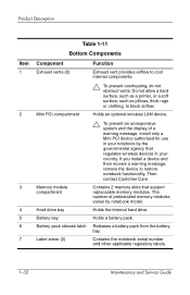
... an optional wireless LAN device. Ä To prevent an unresponsive system and the display of preinstalled memory modules varies by the governmental agency that support replaceable memory modules. Do not allow a hard surface, such as a printer, or a soft surface, such...device to block airflow. Product Description Item 1 2 3 4 5 6 7 Table 1-11 Bottom Components Component Exhaust vents (2) Mini PCI compartment Memory module compartment Hard drive bay Battery bay Battery pack release latch Label areas (2) Function Exhaust vent provides airflow to cool internal components. Ä...
... an optional wireless LAN device. Ä To prevent an unresponsive system and the display of preinstalled memory modules varies by the governmental agency that support replaceable memory modules. Do not allow a hard surface, such as a printer, or a soft surface, such...device to block airflow. Product Description Item 1 2 3 4 5 6 7 Table 1-11 Bottom Components Component Exhaust vents (2) Mini PCI compartment Memory module compartment Hard drive bay Battery bay Battery pack release latch Label areas (2) Function Exhaust vent provides airflow to cool internal components. Ä...
Service Guide
Page 38
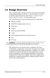
The system board provides the following device connections: ■ Memory module ■ Mini PCI communications devices ■ Hard drive ■ Display ■ Keyboard and TouchPad ■ Audio ■ Intel Pentium M and Celeron M processors ■ Fan &#...
The system board provides the following device connections: ■ Memory module ■ Mini PCI communications devices ■ Hard drive ■ Display ■ Keyboard and TouchPad ■ Audio ■ Intel Pentium M and Celeron M processors ■ Fan &#...
Service Guide
Page 41
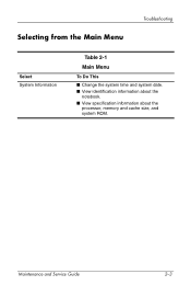
Maintenance and Service Guide 2-3 Selecting from the Main Menu Troubleshooting Select System Information Table 2-1 Main Menu To Do This ■ Change the system time and system date. ■ View identification information about the notebook. ■ View specification information about the processor, memory and cache size, and system ROM.
Maintenance and Service Guide 2-3 Selecting from the Main Menu Troubleshooting Select System Information Table 2-1 Main Menu To Do This ■ Change the system time and system date. ■ View identification information about the notebook. ■ View specification information about the processor, memory and cache size, and system ROM.
Service Guide
Page 43
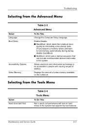
...Advanced Menu Select Language Boot Order Accessibility Options Video Memory Table 2-3 Advanced Menu To Do This Change the Computer Setup language. Maintenance and Service Guide 2-5 Allows electronic and information technology to be accessible to test memory automatically during startup, disable QuickBoot). ■ ...MultiBoot, which starts the notebook more quickly by eliminating some startup tests. (If you suspect a memory failure and want to people with varying ranges of video memory available on hard drives in the system that can include most bootable devices and media in the ...
...Advanced Menu Select Language Boot Order Accessibility Options Video Memory Table 2-3 Advanced Menu To Do This Change the Computer Setup language. Maintenance and Service Guide 2-5 Allows electronic and information technology to be accessible to test memory automatically during startup, disable QuickBoot). ■ ...MultiBoot, which starts the notebook more quickly by eliminating some startup tests. (If you suspect a memory failure and want to people with varying ranges of video memory available on hard drives in the system that can include most bootable devices and media in the ...
Service Guide
Page 73
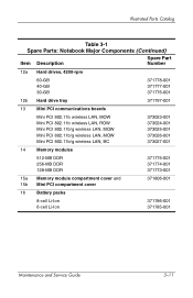
... LAN, BC 373023-001 373024-001 373025-001 373026-001 373027-001 14 Memory modules 512-MB DDR 256-MB DDR 128-MB DDR 371775-001 371774-001 371773-001 15a Memory module compartment cover and 15b Mini PCI compartment cover 371806-001 16 Battery packs 8-cell Li-Ion 6-cell Li-Ion 371786-001 371785-001...
... LAN, BC 373023-001 373024-001 373025-001 373026-001 373027-001 14 Memory modules 512-MB DDR 256-MB DDR 128-MB DDR 371775-001 371774-001 371773-001 15a Memory module compartment cover and 15b Mini PCI compartment cover 371806-001 16 Battery packs 8-cell Li-Ion 6-cell Li-Ion 371786-001 371785-001...

Service Guide
Page 85
... notebook components. Removal and Replacement Procedures 5.2 Disassembly Sequence Chart Use the chart below to determine the section number to remove hard drive bezel Notebook feet 0 Memory module 2 loosened Mini PCI communications board 2 loosened Keyboard cover 2 Keyboard 4 Switch board 2 on all notebook models except HP Pavilion ze4900 1 on HP Pavilion ze4900 Speakers...
... notebook components. Removal and Replacement Procedures 5.2 Disassembly Sequence Chart Use the chart below to determine the section number to remove hard drive bezel Notebook feet 0 Memory module 2 loosened Mini PCI communications board 2 loosened Keyboard cover 2 Keyboard 4 Switch board 2 on all notebook models except HP Pavilion ze4900 1 on HP Pavilion ze4900 Speakers...

Service Guide
Page 93
Removal and Replacement Procedures 5.5 Memory Module 512-MB DDR 256-MB DDR 128-MB DDR Spare Part Number Information 371775-001 371774-001 371773-001 1. Prepare the notebook for disassembly (refer to the notebook. 3. Loosen the 2 PM2.0×4.0 screws 1 that secure the memory module compartment cover to Section 5.3). 2. Removing the Memory Module Compartment Cover 5-10 Maintenance and...
Removal and Replacement Procedures 5.5 Memory Module 512-MB DDR 256-MB DDR 128-MB DDR Spare Part Number Information 371775-001 371774-001 371773-001 1. Prepare the notebook for disassembly (refer to the notebook. 3. Loosen the 2 PM2.0×4.0 screws 1 that secure the memory module compartment cover to Section 5.3). 2. Removing the Memory Module Compartment Cover 5-10 Maintenance and...

Service Guide
Page 94
Removing a Memory Module Reverse the above procedure to the memory module socket. (The module rises up). 6. Maintenance and Service Guide 5-11 Remove the memory module by pulling it away from the memory module socket at a 45-degree angle 2. Spread the 2 retaining tabs 1 that secure the memory module to install a memory module. Removal and Replacement Procedures 5.
Removing a Memory Module Reverse the above procedure to the memory module socket. (The module rises up). 6. Maintenance and Service Guide 5-11 Remove the memory module by pulling it away from the memory module socket at a 45-degree angle 2. Spread the 2 retaining tabs 1 that secure the memory module to install a memory module. Removal and Replacement Procedures 5.
Service Guide
Page 124
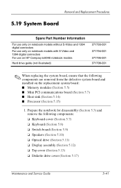
Prepare the notebook for disassembly (Section 5.3) and remove the following components are removed from the defective system board and installed on HP Compaq nx9040 notebook models Hard drive guide (not illustrated) 371793-001 371794-001 371795-001 371798-001 ✎ When replacing the system board, ... digital connectors For use only on notebook models with S-Video and 1394 digital connectors For use on the replacement system board: ■ Memory modules (Section 5.5) ■ Mini PCI communications board (Section 5.7) ■ Heat sink (Section 5.14) ■ Processor (Section 5.15) 1.
Prepare the notebook for disassembly (Section 5.3) and remove the following components are removed from the defective system board and installed on HP Compaq nx9040 notebook models Hard drive guide (not illustrated) 371793-001 371794-001 371795-001 371798-001 ✎ When replacing the system board, ... digital connectors For use only on notebook models with S-Video and 1394 digital connectors For use on the replacement system board: ■ Memory modules (Section 5.5) ■ Mini PCI communications board (Section 5.7) ■ Heat sink (Section 5.14) ■ Processor (Section 5.15) 1.
Service Guide
Page 140
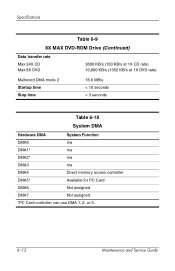
Specifications Table 6-9 8X MAX DVD-ROM Drive (Continued) Data transfer rate Max 24X CD Max 8X DVD 3600 KB/s (150 KB/s at 1X CD rate) 10,800 KB/s (1352 KB/s at 1X DVD rate) Multiword DMA mode 2 Startup time Stop time 16.6 MB/s < 10 seconds < 3 seconds Table 6-10 System DMA Hardware DMA System Function DMA0 n/a DMA1* n/a DMA2* n/a DMA3 n/a DMA4 Direct memory access controller DMA5* Available for PC Card DMA6 Not assigned DMA7 Not assigned *PC Card controller can use DMA 1, 2, or 5. 6-12 Maintenance and Service Guide
Specifications Table 6-9 8X MAX DVD-ROM Drive (Continued) Data transfer rate Max 24X CD Max 8X DVD 3600 KB/s (150 KB/s at 1X CD rate) 10,800 KB/s (1352 KB/s at 1X DVD rate) Multiword DMA mode 2 Startup time Stop time 16.6 MB/s < 10 seconds < 3 seconds Table 6-10 System DMA Hardware DMA System Function DMA0 n/a DMA1* n/a DMA2* n/a DMA3 n/a DMA4 Direct memory access controller DMA5* Available for PC Card DMA6 Not assigned DMA7 Not assigned *PC Card controller can use DMA 1, 2, or 5. 6-12 Maintenance and Service Guide

Service Guide
Page 163
Screw Listing Table C-3 Phillips PM2.0×4.0 Screw Head mm Color Qty. Length Thread Width Black 23 4.0 mm 2.0 mm 4.0 mm Where used: 1 Two screws that secure the memory module compartment cover to the notebook (documented in Section 5.5) 2 Two screws that secure the Mini PCI compartment cover to the notebook (documented in Section 5.6) 3 One screw that secures the top cover to the notebook (documented in Section 5.13) Phillips M2.0×4.0 Screw Locations Maintenance and Service Guide C-7
Screw Listing Table C-3 Phillips PM2.0×4.0 Screw Head mm Color Qty. Length Thread Width Black 23 4.0 mm 2.0 mm 4.0 mm Where used: 1 Two screws that secure the memory module compartment cover to the notebook (documented in Section 5.5) 2 Two screws that secure the Mini PCI compartment cover to the notebook (documented in Section 5.6) 3 One screw that secures the top cover to the notebook (documented in Section 5.13) Phillips M2.0×4.0 Screw Locations Maintenance and Service Guide C-7
Service Guide
Page 179
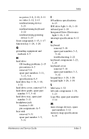
... 4-5 H hard drive OS loading problems 2-15 precautions 4-3 removal 5-6 spare part numbers 3-11, 3-13, 5-6 specifications 6-5 hard drive bay 1-16, 1-18, 1-32 hard drive cover, removal 5-6 hard drive guide, spare part number 3-7, 5-41 hard drive tray, spare part number 3-11...16 spare part numbers 3-5, 5-16 troubleshooting 2-22 keyboard components 1-23, 1-25 keyboard cover removal 5-14 spare part numbers 3-3, 5-14 keypad keys 1-24, 1-26 keypad light 1-28, 1-30 L label area 1-32 left-side components 1-19, 1-21 Logo Kit, spare part number 3-14 M mass storage devices, spare part numbers 3-12 memory...
... 4-5 H hard drive OS loading problems 2-15 precautions 4-3 removal 5-6 spare part numbers 3-11, 3-13, 5-6 specifications 6-5 hard drive bay 1-16, 1-18, 1-32 hard drive cover, removal 5-6 hard drive guide, spare part number 3-7, 5-41 hard drive tray, spare part number 3-11...16 spare part numbers 3-5, 5-16 troubleshooting 2-22 keyboard components 1-23, 1-25 keyboard cover removal 5-14 spare part numbers 3-3, 5-14 keypad keys 1-24, 1-26 keypad light 1-28, 1-30 L label area 1-32 left-side components 1-19, 1-21 Logo Kit, spare part number 3-14 M mass storage devices, spare part numbers 3-12 memory...
Service Guide
Page 180
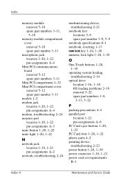
... removal 5-10 spare part numbers 3-11, 5-10 memory module compartment cover removal 5-10 spare part number 3-11 microphone jack location 1-20, 1-22 pin assignments A-4 Mini PCI communications board removal 5-12 spare part numbers 3-..., resetting 1-13 num lock key 1-24, 1-26 numeric lock light 1-28, 1-30 O One-Touch buttons 1-28, 1-30 operating system loading, troubleshooting 2-14 optical drive location 1-16, 1-18 OS loading problems 2-19 removal 5-22 spare part numbers 3-9, 3-13, 5-22 P packing precautions 4-4 parallel port location 1-21 pin assignments A-6 PC Card eject buttons 1-20...
... removal 5-10 spare part numbers 3-11, 5-10 memory module compartment cover removal 5-10 spare part number 3-11 microphone jack location 1-20, 1-22 pin assignments A-4 Mini PCI communications board removal 5-12 spare part numbers 3-..., resetting 1-13 num lock key 1-24, 1-26 numeric lock light 1-28, 1-30 O One-Touch buttons 1-28, 1-30 operating system loading, troubleshooting 2-14 optical drive location 1-16, 1-18 OS loading problems 2-19 removal 5-22 spare part numbers 3-9, 3-13, 5-22 P packing precautions 4-4 parallel port location 1-21 pin assignments A-6 PC Card eject buttons 1-20...
Service Guide
Page 181
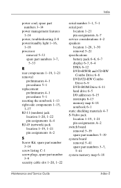
Index power cord, spare part numbers 3-14 power management features 1-14 power, troubleshooting 2-8 power/standby light 1-16, 1-18 processor removal 5-33 spare part numbers 3-7, 5-33 R rear components 1-19, 1-21 removal preliminaries 4-1 procedures 5-1 replacement preliminaries 4-1 ...12 DVD+RW/R and CD-RW Combo Drive 6-8 DVD/CD-RW Combo Drive 6-9 DVD-ROM Drive 6-11 hard drive 6-5 I/O addresses 6-15 interrupts 6-13 memory map 6-18 notebook 6-1 static shielding materials 4-7 S-Video jack location 1-19, 1-21 pin assignments A-2 switch board removal 5-19 spare part numbers 5-19 system board...
Index power cord, spare part numbers 3-14 power management features 1-14 power, troubleshooting 2-8 power/standby light 1-16, 1-18 processor removal 5-33 spare part numbers 3-7, 5-33 R rear components 1-19, 1-21 removal preliminaries 4-1 procedures 5-1 replacement preliminaries 4-1 ...12 DVD+RW/R and CD-RW Combo Drive 6-8 DVD/CD-RW Combo Drive 6-9 DVD-ROM Drive 6-11 hard drive 6-5 I/O addresses 6-15 interrupts 6-13 memory map 6-18 notebook 6-1 static shielding materials 4-7 S-Video jack location 1-19, 1-21 pin assignments A-2 switch board removal 5-19 spare part numbers 5-19 system board...


