Instruction Manual
Page 3
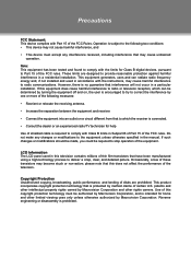
... of shielded cable is required to the equipment unless otherwise specified in the manual. Note: This equipment has been tested and found to comply with Class B limits in ...Subpart B of Part 15 of the FCC rules. LCD Information The LCD panel used in a particular installation. If such changes or modifications should be made, you... picture. please note that is connected. •• Consult the dealer or an experienced radio/TV technician for home and other rights owners. Do not make any interference received, including interference that ...
... of shielded cable is required to the equipment unless otherwise specified in the manual. Note: This equipment has been tested and found to comply with Class B limits in ...Subpart B of Part 15 of the FCC rules. LCD Information The LCD panel used in a particular installation. If such changes or modifications should be made, you... picture. please note that is connected. •• Consult the dealer or an experienced radio/TV technician for home and other rights owners. Do not make any interference received, including interference that ...
Instruction Manual
Page 19
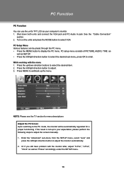
NOTE: Please see the TV section for a proper functioning. See the "Cable Connection" section. 222 Turn on the units and press the MODE button to select VGA PC Setup Menu Various features can use the unit's TFT LCD as "Phase" accordingly under the SETUP menu. 13 While working with the monitor ... left/right direction button to adjust. 333 Press MENU to exit/back up to your expectation, please perform the following steps to adjust the screen manually . 111 Enter the "Advanced" sub-menu from the SETUP menu, select "Auto" and press the left /right direction button to select the desired...
NOTE: Please see the TV section for a proper functioning. See the "Cable Connection" section. 222 Turn on the units and press the MODE button to select VGA PC Setup Menu Various features can use the unit's TFT LCD as "Phase" accordingly under the SETUP menu. 13 While working with the monitor ... left/right direction button to adjust. 333 Press MENU to exit/back up to your expectation, please perform the following steps to adjust the screen manually . 111 Enter the "Advanced" sub-menu from the SETUP menu, select "Auto" and press the left /right direction button to select the desired...
Instruction Manual
Page 20
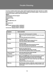
...develop a malfunction, unplug the player for Frequently Asked Questions (FAQs) and firmware updates. Address COBY Electronics Technical Support 56-65 Rust Street Maspeth, NY 11378 Email [email protected] Web www.cobyusa...8226;• Check if the main power has been switched on. •• Try another TV channel •• Check if the system connection is proper and secure. •• Check...the antenna. •• Make sure the POWER button on the unit has been turned on manually. •• Remove the obstacles between the remote control and the player. ••...
...develop a malfunction, unplug the player for Frequently Asked Questions (FAQs) and firmware updates. Address COBY Electronics Technical Support 56-65 Rust Street Maspeth, NY 11378 Email [email protected] Web www.cobyusa...8226;• Check if the main power has been switched on. •• Try another TV channel •• Check if the system connection is proper and secure. •• Check...the antenna. •• Make sure the POWER button on the unit has been turned on manually. •• Remove the obstacles between the remote control and the player. ••...
Instruction Manual
Page 22
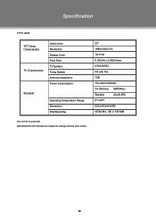
Specification TFTV 2224 TFT Panel Characteristic TV Charactoristic Active Area Resolution Display Color Pixel Pitch TV System Tuing System Antenna Impedance Power Consumption Standard Operating Temperature Range Dimension Wall Mounting 22" 1680x1050 mm 16.77 M 0.282(H) x 0.282(V)mm ATSC/NTSC FS with PLL 75Ω 110-240V 50/60Hz On Working 60W(Max) Speaker 2x(4Ω,5W) 0ºc-40ºc 527x167x444 MM VESA M4, 100 X 100 MM P/N: 907-FV15-2400-00R Specifications and manual are subject to change without prior notice. 16
Specification TFTV 2224 TFT Panel Characteristic TV Charactoristic Active Area Resolution Display Color Pixel Pitch TV System Tuing System Antenna Impedance Power Consumption Standard Operating Temperature Range Dimension Wall Mounting 22" 1680x1050 mm 16.77 M 0.282(H) x 0.282(V)mm ATSC/NTSC FS with PLL 75Ω 110-240V 50/60Hz On Working 60W(Max) Speaker 2x(4Ω,5W) 0ºc-40ºc 527x167x444 MM VESA M4, 100 X 100 MM P/N: 907-FV15-2400-00R Specifications and manual are subject to change without prior notice. 16


