148GTLE_Eng-Spa
Page 10
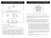
...follows: 3 4 2 1 Fig. 3. Before soldering the wire to the pin receptacle body, make sure that the housing and the knurled ring of Fig. 3 are aligned, the retaining screw is not available, the pin receptacle body can be tightened to secure the housing to the threaded hole in the pin receptacle... transceiver. 17 If a vise or clamping tool is then screwed into the microphone jack on the threaded portion of the plug. Note the location of the microphone plug wiring, connect and secure the microphone plug in the pin receptacle body. The two cable clamp retainer screws should secure ...
...follows: 3 4 2 1 Fig. 3. Before soldering the wire to the pin receptacle body, make sure that the housing and the knurled ring of Fig. 3 are aligned, the retaining screw is not available, the pin receptacle body can be tightened to secure the housing to the threaded hole in the pin receptacle... transceiver. 17 If a vise or clamping tool is then screwed into the microphone jack on the threaded portion of the plug. Note the location of the microphone plug wiring, connect and secure the microphone plug in the pin receptacle body. The two cable clamp retainer screws should secure ...
