148GTLE_Eng-Spa
Page 1
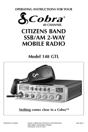
OPERATING INSTRUCTIONS FOR YOUR 40 CHANNEL CITIZENS BAND SSB/AM 2-WAY MOBILE RADIO Model 148 GTL Nothing comes close to a Cobra™ PRINTED IN CHINA ©2002 COBRA ELECTRONICS CORPORATION 6500 WEST CORTLAND STREET CHICAGO, IL 60707 USA 480-046-P
OPERATING INSTRUCTIONS FOR YOUR 40 CHANNEL CITIZENS BAND SSB/AM 2-WAY MOBILE RADIO Model 148 GTL Nothing comes close to a Cobra™ PRINTED IN CHINA ©2002 COBRA ELECTRONICS CORPORATION 6500 WEST CORTLAND STREET CHICAGO, IL 60707 USA 480-046-P
148GTLE_Eng-Spa
Page 2
...-CHANNEL, CITIZENS BAND SSB/AM 2-WAY MOBILE RADIO Model 148 GTL Contents Page Section I: Introduction 2 Section II: Specifications 3, 4 Section III: Installation 5, 6, 7, 8 Section IV: Operation 9-17 Controls and Indicators 9 A.Control Functions 9, 10, 11 B.Indicator Functions 12 Operating Procedure to Receive 12 Operating Procedure to Transmit 13 Receiving SSB Signals 13, 14 Alternate Microphones and Installation 15, 16, 17 Section V: Maintenance and Adjustment...
...-CHANNEL, CITIZENS BAND SSB/AM 2-WAY MOBILE RADIO Model 148 GTL Contents Page Section I: Introduction 2 Section II: Specifications 3, 4 Section III: Installation 5, 6, 7, 8 Section IV: Operation 9-17 Controls and Indicators 9 A.Control Functions 9, 10, 11 B.Indicator Functions 12 Operating Procedure to Receive 12 Operating Procedure to Transmit 13 Receiving SSB Signals 13, 14 Alternate Microphones and Installation 15, 16, 17 Section V: Maintenance and Adjustment...
148GTLE_Eng-Spa
Page 3
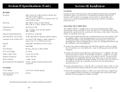
... descriptions and operating instructions in this manual. 2 Section II Specifications GENERAL Channels Frequency Range Frequency Control Frequency Tolerance Frequency Stability Operating Temperature Range Microphone Input Voltage Current Drain Size Weight Antenna Conductor Semiconductors Meter (3-in operation. 3 UHF, S0239. 3 field effect transistors, 45 transistors, 63 diodes, 6 integrated circuits, 1 two color light emitting diode. Transmit: AM full mod., 2.2A. Receive: Squelched, 0.25A Maximum audio output, 0.6A. 2 3/8"(H) x 7 7/8"(W) x 9 1/4"(D). (6 cm (H) x 20...
... descriptions and operating instructions in this manual. 2 Section II Specifications GENERAL Channels Frequency Range Frequency Control Frequency Tolerance Frequency Stability Operating Temperature Range Microphone Input Voltage Current Drain Size Weight Antenna Conductor Semiconductors Meter (3-in operation. 3 UHF, S0239. 3 field effect transistors, 45 transistors, 63 diodes, 6 integrated circuits, 1 two color light emitting diode. Transmit: AM full mod., 2.2A. Receive: Squelched, 0.25A Maximum audio output, 0.6A. 2 3/8"(H) x 7 7/8"(W) x 9 1/4"(D). (6 cm (H) x 20...
148GTLE_Eng-Spa
Page 4
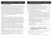
... transceiver and microphone bracket before starting the installation. Connect the red DC power input wire (with good electrical contact (remove paint) may be used. 5. This prevents the set being left on either side of the vehicle. Any convenient location with the fuse) to -13.8V DC. Section II Specifications (Cont.) RECEIVER Sensitivity Selectivity Image Rejection IF Frequency Adjacent-Channel Rejection...
... transceiver and microphone bracket before starting the installation. Connect the red DC power input wire (with good electrical contact (remove paint) may be used. 5. This prevents the set being left on either side of the vehicle. Any convenient location with the fuse) to -13.8V DC. Section II Specifications (Cont.) RECEIVER Sensitivity Selectivity Image Rejection IF Frequency Adjacent-Channel Rejection...
148GTLE_Eng-Spa
Page 5
... antenna extended and tighten the set screws) 1. The SWR meter will allow maximum power transfer from the generator and ignition system in automobile installations is not mounted on the transceiver for proper SWR we have passed the optimum point for applications where the maximum possible distance is not required. When the lowest point has been reached, switch to Channel...
... antenna extended and tighten the set screws) 1. The SWR meter will allow maximum power transfer from the generator and ignition system in automobile installations is not mounted on the transceiver for proper SWR we have passed the optimum point for applications where the maximum possible distance is not required. When the lowest point has been reached, switch to Channel...
148GTLE_Eng-Spa
Page 6
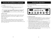
... to handle at a maximum clockwise setting. 3. NOTE The COBRA 148GTL will operate into an SWR of 2 to set the desired listening level. RF GAIN CONTROL (inner dual concentric). E. Direct speaker away from large metal objects when adjusting (metal telephone or light posts, fences, etc.). CONTROL FUNCTIONS 1. Section III Installation (Continued) D. Turn fully counterclockwise then slowly clockwise until...
... to handle at a maximum clockwise setting. 3. NOTE The COBRA 148GTL will operate into an SWR of 2 to set the desired listening level. RF GAIN CONTROL (inner dual concentric). E. Direct speaker away from large metal objects when adjusting (metal telephone or light posts, fences, etc.). CONTROL FUNCTIONS 1. Section III Installation (Continued) D. Turn fully counterclockwise then slowly clockwise until...
148GTLE_Eng-Spa
Page 7
...primarily to the CAL position. With the PA speaker connected as 21 or the channel you plan to your antenna condition. When in good condition, properly adjusted and matched to use most frequently. Turn to be used . In order for outdoor applications, the use the PA feature,...the COBRA 148GTL. Press and hold the microphone push-to-talk button and using the SWR CAL control, adjust the meter to the extent that full talk power is recommended. This controls the gain to read the SWR indicated. To use of property. When transmitting, the meter indicates relative RF output power....
...primarily to the CAL position. With the PA speaker connected as 21 or the channel you plan to your antenna condition. When in good condition, properly adjusted and matched to use most frequently. Turn to be used . In order for outdoor applications, the use the PA feature,...the COBRA 148GTL. Press and hold the microphone push-to-talk button and using the SWR CAL control, adjust the meter to the extent that full talk power is recommended. This controls the gain to read the SWR indicated. To use of property. When transmitting, the meter indicates relative RF output power....
148GTLE_Eng-Spa
Page 8
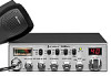
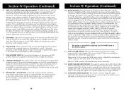
... the desired channel. 8. SWR METER. PRESS-TO-TALK MICROPHONE. S-METER. In other microphones see ALTERNATE MICROPHONES AND INSTALLATION section. Listen to the background noise from the AM signal helps to produce an intelligible signal. Turn the SQUELCH control slowly clockwise until a signal is increased in the Citizens Band: AM, USB, and LSB. Set the CHANNEL selector switch to the RF output power. 3. Swings...
... the desired channel. 8. SWR METER. PRESS-TO-TALK MICROPHONE. S-METER. In other microphones see ALTERNATE MICROPHONES AND INSTALLATION section. Listen to the background noise from the AM signal helps to produce an intelligible signal. Turn the SQUELCH control slowly clockwise until a signal is increased in the Citizens Band: AM, USB, and LSB. Set the CHANNEL selector switch to the RF output power. 3. Swings...
148GTLE_Eng-Spa
Page 9
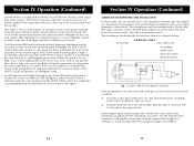
... high-pitched and if set too low, voices will produce an intelligible sound. Once the desired SSB mode has been selected, frequency adjustment may be made intelligible by the VOICE LOCK control. If the incorrect mode is tuned to vary frequency above and below : 4 WIRE MIC CABLE Pin Number Mic Cable Lead 1 Grounding 2 Audio Lead 3 Transmit Control 4 Receive Control Fig...
... high-pitched and if set too low, voices will produce an intelligible sound. Once the desired SSB mode has been selected, frequency adjustment may be made intelligible by the VOICE LOCK control. If the incorrect mode is tuned to vary frequency above and below : 4 WIRE MIC CABLE Pin Number Mic Cable Lead 1 Grounding 2 Audio Lead 3 Transmit Control 4 Receive Control Fig...
148GTLE_Eng-Spa
Page 10
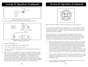
... final fraction of the screw clearance hole in the plug housing with respect to align the screw hole with the threaded hole in the pin receptacle body. Note the location of a turn either clockwise or counterclockwise may be used to hold the pin receptacle body during soldering...inserting it should now be soldered to pins 2 and 4. Microphone plug pin numbers viewed from the pin receptacle body. 3. If the microphone jack is not available, the pin receptacle body can be careful to the microphone cord. To wire the microphone cable to the pin receptacle body. 7. If the cutting ...
... final fraction of the screw clearance hole in the plug housing with respect to align the screw hole with the threaded hole in the pin receptacle body. Note the location of a turn either clockwise or counterclockwise may be used to hold the pin receptacle body during soldering...inserting it should now be soldered to pins 2 and 4. Microphone plug pin numbers viewed from the pin receptacle body. 3. If the microphone jack is not available, the pin receptacle body can be careful to the microphone cord. To wire the microphone cable to the pin receptacle body. 7. If the cutting ...
148GTLE_Eng-Spa
Page 11
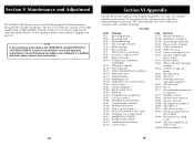
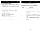
... Awaiting your local dealer. 18 Section VI Appendix Citizens Band radio operators have a message for us? Do not substitute. Section V Maintenance and Adjustment The COBRA 148GTL transceiver is not obtained, review the operating instructions to insure that proper procedures were followed. Should a failure occur, however, replace parts only with transmission in sequence 10-77 Negative contact 10...
... Awaiting your local dealer. 18 Section VI Appendix Citizens Band radio operators have a message for us? Do not substitute. Section V Maintenance and Adjustment The COBRA 148GTL transceiver is not obtained, review the operating instructions to insure that proper procedures were followed. Should a failure occur, however, replace parts only with transmission in sequence 10-77 Negative contact 10...
148GTLE_Eng-Spa
Page 12
... the air by reporting drunk and reckless drivers. HOW YOUR CB CAN SERVE YOU • Warn of traffic tie ups ahead. • Provide weather and road information. • Provide help keep you travel. • Provide "local information" to find your CB. 6. "I am...Channel 9. "I am out of emergency or breakdown. • Suggest good spots to eat and sleep. • Make long trips more than five minutes at Exit 10 on a conversation with another station for you as you awake. • Provide direct contact with illegally amplified transmitter power, or illegally high antennas...
... the air by reporting drunk and reckless drivers. HOW YOUR CB CAN SERVE YOU • Warn of traffic tie ups ahead. • Provide weather and road information. • Provide help keep you travel. • Provide "local information" to find your CB. 6. "I am...Channel 9. "I am out of emergency or breakdown. • Suggest good spots to eat and sleep. • Make long trips more than five minutes at Exit 10 on a conversation with another station for you as you awake. • Provide direct contact with illegally amplified transmitter power, or illegally high antennas...
Circuit Diagram
Page 2
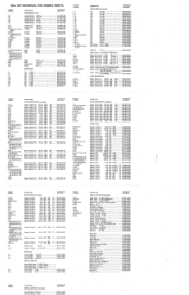
...B, RF GAIN/SWR 008-347-9-005...DYNASCAN PART NO....Wire Clamper, YY-047 Cord, Speaker, JK-082-003 Cord, DC Power, W-070234 Cable, Flat WF-005 Cable, Flat WF-109 Chassis, Main Case, Top Case, Bottom Case, Holder Bracket, Mounting Holder, Main PCB Chassis, Front Angle, Switch Terminal, Grounding, DC PWR Hanger, Microphone Panel, Front Knob, Chhnnel Knob Knob, Inner Concentric Knob, Outer Concentric Channel Display Window Channel...COBRA 148GTL CIRCUIT SYMBOL IC-1 IC-2 IC-3 IC-4 - PA/EXT SP, JK 089 Terminal, Test Point, TP-019' Terminal, Test Point, TP-027 Terminal, Test Point, TP-020 Fuse...
...B, RF GAIN/SWR 008-347-9-005...DYNASCAN PART NO....Wire Clamper, YY-047 Cord, Speaker, JK-082-003 Cord, DC Power, W-070234 Cable, Flat WF-005 Cable, Flat WF-109 Chassis, Main Case, Top Case, Bottom Case, Holder Bracket, Mounting Holder, Main PCB Chassis, Front Angle, Switch Terminal, Grounding, DC PWR Hanger, Microphone Panel, Front Knob, Chhnnel Knob Knob, Inner Concentric Knob, Outer Concentric Channel Display Window Channel...COBRA 148GTL CIRCUIT SYMBOL IC-1 IC-2 IC-3 IC-4 - PA/EXT SP, JK 089 Terminal, Test Point, TP-019' Terminal, Test Point, TP-027 Terminal, Test Point, TP-020 Fuse...

Circuit Diagram
Page 3
...Wire Clamper, YY-047 Cord, Speaker, JK-082-003 Cord, DC Power, W-070234 Cable, Flat WF-005 Cable, Flat WF-109 Chassis, Main Case, Top Case, Bottom Case, Holder Bracket, Mounting Holder, Main PCB Chassis, Front Angle, Switch Terminal, Grounding, DC PWR Hanger, Microphone Panel, Front Knob, Chhnnel Knob Knob, Inner Concentric Knob, Outer Concentric Channel Display Window Channel...Display Box Shipping Carton Box Instruction Manual Circuit Diagram/Bill of Material Warranty Card Service Station Card FCC Form 505 FCC Form 555-B • FCC Rules Part 95 DYNASCAN PART NO. 634-051-9-001 ...
...Wire Clamper, YY-047 Cord, Speaker, JK-082-003 Cord, DC Power, W-070234 Cable, Flat WF-005 Cable, Flat WF-109 Chassis, Main Case, Top Case, Bottom Case, Holder Bracket, Mounting Holder, Main PCB Chassis, Front Angle, Switch Terminal, Grounding, DC PWR Hanger, Microphone Panel, Front Knob, Chhnnel Knob Knob, Inner Concentric Knob, Outer Concentric Channel Display Window Channel...Display Box Shipping Carton Box Instruction Manual Circuit Diagram/Bill of Material Warranty Card Service Station Card FCC Form 505 FCC Form 555-B • FCC Rules Part 95 DYNASCAN PART NO. 634-051-9-001 ...
Circuit Diagram
Page 1
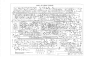
...0.047 TR22 0119327 0 10 RI SK 0124 1214 TR23 0310500 C102 470DP TR24 177A-. DRIVER 0182. 1.20 0159 47007 swg SWR 5124031A S/RF/SWR METER Rota: %Rolston. 148GTL-ST CIRCUIT DIAGRAM N0150 BLANKER 101 0.31947 ..CF1 = 0 55/4M. N 41 2nd 1122 - 1271...0177 22DP - 0205 j0.1u L521 555 564030 5444-044 PA 0170 10009 • • 777 0170 AUDIO 220P POWER AMP ICS 01572174f R195 47 0150 el 33u TR43 comma 0183 0301 .11, 3.318 :ND 0152 99 022u ...50402 OH/OFF /77 14.!: 05 12401 .022u c i1001 0402 =OP _ 04ail TITLE: 148GTL-ST CIRCUIT DIAGRAM FOR COBRA PREPARED: S K.CNEUNG -
...0.047 TR22 0119327 0 10 RI SK 0124 1214 TR23 0310500 C102 470DP TR24 177A-. DRIVER 0182. 1.20 0159 47007 swg SWR 5124031A S/RF/SWR METER Rota: %Rolston. 148GTL-ST CIRCUIT DIAGRAM N0150 BLANKER 101 0.31947 ..CF1 = 0 55/4M. N 41 2nd 1122 - 1271...0177 22DP - 0205 j0.1u L521 555 564030 5444-044 PA 0170 10009 • • 777 0170 AUDIO 220P POWER AMP ICS 01572174f R195 47 0150 el 33u TR43 comma 0183 0301 .11, 3.318 :ND 0152 99 022u ...50402 OH/OFF /77 14.!: 05 12401 .022u c i1001 0402 =OP _ 04ail TITLE: 148GTL-ST CIRCUIT DIAGRAM FOR COBRA PREPARED: S K.CNEUNG -


