Hardware Maintenance Manual
Page 73
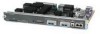
... channel-group and timeslots to enable routing protocols and adjust the interface characteristics. Refer to the printed Router Products Configuration Guide and Router Products Command Reference publications or UniverCD for a summary of the configuration subcommands, to complete the configuration, enter ...-group to exit the configuration mode. Step 12 Exit the privileged level and return to the interface with show commands. Installing the Router 3-15 Step 10 After including all of the configuration options available and additional instructions for mapping. Router(config-...
... channel-group and timeslots to enable routing protocols and adjust the interface characteristics. Refer to the printed Router Products Configuration Guide and Router Products Command Reference publications or UniverCD for a summary of the configuration subcommands, to complete the configuration, enter ...-group to exit the configuration mode. Step 12 Exit the privileged level and return to the interface with show commands. Installing the Router 3-15 Step 10 After including all of the configuration options available and additional instructions for mapping. Router(config-...
Hardware Maintenance Manual
Page 75
Making ATM Connections If you installed a new ATM interface module or if you must enter the configuration mode. The following information: • ATM transceiver ... configuration is the default): Router(config-if)#atm sonet stm-1 Step 4 Assign protocol addresses to the printed Router Products Configuration Guide and Router Products Command Reference publications or UniverCD for a summary of an existing module, you want to change the configuration of... in the existing configuration. Refer to the interface: Router(config-if)# ip address 1.1.1.1 255.255.255.0 Installing the Router 3-17
Making ATM Connections If you installed a new ATM interface module or if you must enter the configuration mode. The following information: • ATM transceiver ... configuration is the default): Router(config-if)#atm sonet stm-1 Step 4 Assign protocol addresses to the printed Router Products Configuration Guide and Router Products Command Reference publications or UniverCD for a summary of an existing module, you want to change the configuration of... in the existing configuration. Refer to the interface: Router(config-if)# ip address 1.1.1.1 255.255.255.0 Installing the Router 3-17

Hardware Maintenance Manual
Page 104
... both sides). 1. The socket guide posts release through the SIMM holes (on both sides). 1. Place the removed SIMM in an antistatic bag to rock forward. Pull the locking spring clips outward to enable the SIMM to the next section, "Installing Main Memory SIMMs." 5-10 Cisco 4000 Series Hardware Installation and Maintenance Step 5 Hold the...
... both sides). 1. The socket guide posts release through the SIMM holes (on both sides). 1. Place the removed SIMM in an antistatic bag to rock forward. Pull the locking spring clips outward to enable the SIMM to the next section, "Installing Main Memory SIMMs." 5-10 Cisco 4000 Series Hardware Installation and Maintenance Step 5 Hold the...
Hardware Maintenance Manual
Page 105
... Memory SIMMs Follow this chapter. Connect the equipment end of the wrist strap to install main memory SIMMs. Step 1 Put on the right and the component side away from you with the connector edge at the bottom. (See Figure 5-7.) Step 4 ...-M and Figure 5-6 for the Cisco 4500-M and Cisco 4700. Caution Handle SIMMs by mishandling. When the SIMM is straight and that it into place. Maintaining and Upgrading the Router 5-11 Step 5 Ensure that each SIMM is properly seated, the socket guide posts will insert through the alignment holes, and the connector springs will...
... Memory SIMMs Follow this chapter. Connect the equipment end of the wrist strap to install main memory SIMMs. Step 1 Put on the right and the component side away from you with the connector edge at the bottom. (See Figure 5-7.) Step 4 ...-M and Figure 5-6 for the Cisco 4500-M and Cisco 4700. Caution Handle SIMMs by mishandling. When the SIMM is straight and that it into place. Maintaining and Upgrading the Router 5-11 Step 5 Ensure that each SIMM is properly seated, the socket guide posts will insert through the alignment holes, and the connector springs will...

Hardware Maintenance Manual
Page 106
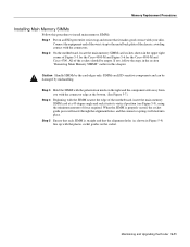
The socket guide posts insert through the SIMM holes (on both sides). 4. Memory Replacement Procedures Figure 5-9 Installing Main Memory SIMMs Top view Front of the SIMM when it is fully installed (on the SIMM and do not use excessive force on both sides). 4. Insert the SIMM ...resistance, but do not touch the surface components to the section "Replacing Network Processor Modules" later in this chapter. 5-12 Cisco 4000 Series Hardware Installation and Maintenance H1152 Caution You will clip the back of the chassis 1. If you are done with all SIMM replacement procedures...
The socket guide posts insert through the SIMM holes (on both sides). 4. Memory Replacement Procedures Figure 5-9 Installing Main Memory SIMMs Top view Front of the SIMM when it is fully installed (on the SIMM and do not use excessive force on both sides). 4. Insert the SIMM ...resistance, but do not touch the surface components to the section "Replacing Network Processor Modules" later in this chapter. 5-12 Cisco 4000 Series Hardware Installation and Maintenance H1152 Caution You will clip the back of the chassis 1. If you are done with all SIMM replacement procedures...

Hardware Maintenance Manual
Page 111
Caution Handle SIMMs by mishandling. SIMMs are ESD-sensitive components and can be damaged by the edges only. Memory Replacement Procedures Installing Flash-Memory SIMMs You upgrade boot helper Flash memory by replacing the existing SIMM (labeled System Flash Memory 0), or by adding a second SIMM...at a 45-degree angle and rock it into its vertical position. (See Figure 5-5 and Figure 5-6.) When the SIMM is properly seated, the socket guide posts will insert through the alignment holes, and the locking springs will click into place. Step 3 Referring to Figure 5-12, insert the Flash-memory ...
Caution Handle SIMMs by mishandling. SIMMs are ESD-sensitive components and can be damaged by the edges only. Memory Replacement Procedures Installing Flash-Memory SIMMs You upgrade boot helper Flash memory by replacing the existing SIMM (labeled System Flash Memory 0), or by adding a second SIMM...at a 45-degree angle and rock it into its vertical position. (See Figure 5-5 and Figure 5-6.) When the SIMM is properly seated, the socket guide posts will insert through the alignment holes, and the locking springs will click into place. Step 3 Referring to Figure 5-12, insert the Flash-memory ...

Hardware Maintenance Manual
Page 112
.... 3. The locking spring will clip the front side of each SIMM to make sure that the alignment holes are lined up with the plastic socket guides. Polarization notch Side view 1. Insert the SIMM into the socket at an angle 45° from vertical. 2. Push the SIMM down and back.... will feel some resistance, but do not touch the surface components to the section "Replacing Network Processor Modules" later in this chapter. 5-18 Cisco 4000 Series Hardware Installation and Maintenance Push the SIMM down and back. 3. H2474 Caution You will clip the front side of the chassis 1.
.... 3. The locking spring will clip the front side of each SIMM to make sure that the alignment holes are lined up with the plastic socket guides. Polarization notch Side view 1. Insert the SIMM into the socket at an angle 45° from vertical. 2. Push the SIMM down and back.... will feel some resistance, but do not touch the surface components to the section "Replacing Network Processor Modules" later in this chapter. 5-18 Cisco 4000 Series Hardware Installation and Maintenance Push the SIMM down and back. 3. H2474 Caution You will clip the front side of the chassis 1.

Hardware Maintenance Manual
Page 115
http://www.cisco.com/univercd/cc/td/doc/product/access/acs_mod/cis4000/4000 m/4000sig/index.htm Thank You, Cisco Technical Documentation Cable Specifications To access the cable specifications information, click on the link below and select the "Cabling Specifications" chapter of the Cisco 4000 Series Installation Guide.
http://www.cisco.com/univercd/cc/td/doc/product/access/acs_mod/cis4000/4000 m/4000sig/index.htm Thank You, Cisco Technical Documentation Cable Specifications To access the cable specifications information, click on the link below and select the "Cabling Specifications" chapter of the Cisco 4000 Series Installation Guide.
