
Hardware Maintenance Manual
Page 9
...Figure 2-24 Figure 2-25 Figure 2-26 Figure 2-27 Figure 2-28 Figure 2-29 Figure 2-30 Figure 2-31 Figure 2-32 Cisco 4000 Series Chassis-Front Panel 1-2 Cisco 4000 Series Memory Systems and Software Images 1-4 Installation Checklist 2-5 Router-Rear View Showing Slot Numbering and Interface Ports 2-7 Router-...26 Multimode FDDI Network Interface Connector, MIC Type 2-26 Dual-Attachment Multimode FDDI Module-End View 2-27 Dual-Attachment FDDI Optical Bypass Switch and PHY Connections 2-27 Single-Attachment Multimode FDDI Module-End View 2-28 4-Port BRI Network Processor Module 2-29 8-Port BRI Network...
...Figure 2-24 Figure 2-25 Figure 2-26 Figure 2-27 Figure 2-28 Figure 2-29 Figure 2-30 Figure 2-31 Figure 2-32 Cisco 4000 Series Chassis-Front Panel 1-2 Cisco 4000 Series Memory Systems and Software Images 1-4 Installation Checklist 2-5 Router-Rear View Showing Slot Numbering and Interface Ports 2-7 Router-...26 Multimode FDDI Network Interface Connector, MIC Type 2-26 Dual-Attachment Multimode FDDI Module-End View 2-27 Dual-Attachment FDDI Optical Bypass Switch and PHY Connections 2-27 Single-Attachment Multimode FDDI Module-End View 2-28 4-Port BRI Network Processor Module 2-29 8-Port BRI Network...
Hardware Maintenance Manual
Page 24
...not perform any action that creates a potential hazard to people or makes the equipment unsafe. Always check. • Look carefully for help to power lines, remove jewelry (including rings, necklaces, and watches). Use caution; do not become a victim yourself. - Determine if the person needs rescue breathing or... and protect the equipment. • Keep the chassis area clear and dust-free during and after installation. • Always turn off switch in the room in which you can weld the metal object to the system. - Metal objects will help . - then take appropriate action...
...not perform any action that creates a potential hazard to people or makes the equipment unsafe. Always check. • Look carefully for help to power lines, remove jewelry (including rings, necklaces, and watches). Use caution; do not become a victim yourself. - Determine if the person needs rescue breathing or... and protect the equipment. • Keep the chassis area clear and dust-free during and after installation. • Always turn off switch in the room in which you can weld the metal object to the system. - Metal objects will help . - then take appropriate action...

Hardware Maintenance Manual
Page 28
...TIA-449, or EIA-530 electrical interface. • Ethernet transceiver. • Token Ring media attachment unit (MAU). • Optical bypass switch or concentrator for each serial port to an external network. • To connect a serial port to a T1 network, you need the..., Number 1 and Number 2 Phillips • One serial port adapter cable for multimode Fiber Distributed Data Interface (FDDI) connections. 2-6 Cisco 4000 Series Hardware Installation and Maintenance Configuration changes - Site Log entries might need a T1 channel service unit/data service unit (CSU/DSU...
...TIA-449, or EIA-530 electrical interface. • Ethernet transceiver. • Token Ring media attachment unit (MAU). • Optical bypass switch or concentrator for each serial port to an external network. • To connect a serial port to a T1 network, you need the..., Number 1 and Number 2 Phillips • One serial port adapter cable for multimode Fiber Distributed Data Interface (FDDI) connections. 2-6 Cisco 4000 Series Hardware Installation and Maintenance Configuration changes - Site Log entries might need a T1 channel service unit/data service unit (CSU/DSU...

Hardware Maintenance Manual
Page 29
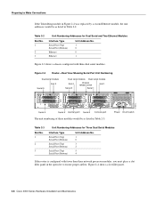
... chassis, the unit numbering of the network processor modules increments from zero counting from the rear, the power cable and power switch appear on how to remove and replace network processor modules, see the sections "Removing Network Processor Modules" and "Replacing Network Processor... Modules" in which the system scans the network processor modules. For information on the right side of the power cable and switch. (See Figure 2-2.) Figure 2-2 Router-Rear View Showing Slot Numbering and Interface Ports Slot 3 Token Ring port 10BaseT Chassis Serial interface...
... chassis, the unit numbering of the network processor modules increments from zero counting from the rear, the power cable and power switch appear on how to remove and replace network processor modules, see the sections "Removing Network Processor Modules" and "Replacing Network Processor... Modules" in which the system scans the network processor modules. For information on the right side of the power cable and switch. (See Figure 2-2.) Figure 2-2 Router-Rear View Showing Slot Numbering and Interface Ports Slot 3 Token Ring port 10BaseT Chassis Serial interface...
Hardware Maintenance Manual
Page 30
Preparing to ensure proper airflow. Figure 2-4 shows a slot filler panel. INPUT 100-240VAC 50/60HZ 3.0-1.5 AMPS Power On/off switch Table 2-3 Slot No. 1 2 3 Unit Numbering Addresses for Dual Serial and Two Ethernet Modules Interface Type Serial Port (Top) Serial ...the Token Ring module in Figure 2-2 was replaced by a second Ethernet module, the unit addresses would be as listed in Table 2-2. H1402 a 2-8 Cisco 4000 Series Hardware Installation and Maintenance Table 2-2 Slot No. 1 2 3 Unit Numbering Addresses for Three Dual Serial Modules Interface Type Serial Port (Top)...
Preparing to ensure proper airflow. Figure 2-4 shows a slot filler panel. INPUT 100-240VAC 50/60HZ 3.0-1.5 AMPS Power On/off switch Table 2-3 Slot No. 1 2 3 Unit Numbering Addresses for Dual Serial and Two Ethernet Modules Interface Type Serial Port (Top) Serial ...the Token Ring module in Figure 2-2 was replaced by a second Ethernet module, the unit addresses would be as listed in Table 2-2. H1402 a 2-8 Cisco 4000 Series Hardware Installation and Maintenance Table 2-2 Slot No. 1 2 3 Unit Numbering Addresses for Three Dual Serial Modules Interface Type Serial Port (Top)...
Hardware Maintenance Manual
Page 49
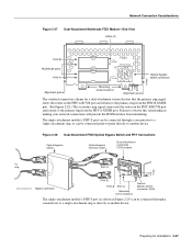
... ring, or can be connected point-to-point directly to another device. Figure 2-28 Dual-Attachment FDDI Optical Bypass Switch and PHY Connections Optical bypass switch Optical bypass interface cable Dual-attachment multimode FDDI module To ring PHY-A PHY-B PHY-A RING OP FDDI OPT-BYPASS ...RING OP H1405a Bypass operation PHY-B PHY-B PHY-A Mounting screw locations Optical bypass switch connector (DIN) The single-attachment module's PHY-S port (as shown in making your network connections will prevent the FDDI interface from the...
... ring, or can be connected point-to-point directly to another device. Figure 2-28 Dual-Attachment FDDI Optical Bypass Switch and PHY Connections Optical bypass switch Optical bypass interface cable Dual-attachment multimode FDDI module To ring PHY-A PHY-B PHY-A RING OP FDDI OPT-BYPASS ...RING OP H1405a Bypass operation PHY-B PHY-B PHY-A Mounting screw locations Optical bypass switch connector (DIN) The single-attachment module's PHY-S port (as shown in making your network connections will prevent the FDDI interface from the...
Hardware Maintenance Manual
Page 50
... if power is a passive optical device powered by the FDDI module. An optical bypass switch is lost , the optical bypass switch is detected or if the operator chooses to take the router out of the ring. 2-28 Cisco 4000 Series Hardware Installation and Maintenance Network Connection Considerations Figure 2-29 Single-Attachment Multimode FDDI...
... if power is a passive optical device powered by the FDDI module. An optical bypass switch is lost , the optical bypass switch is detected or if the operator chooses to take the router out of the ring. 2-28 Cisco 4000 Series Hardware Installation and Maintenance Network Connection Considerations Figure 2-29 Single-Attachment Multimode FDDI...
Hardware Maintenance Manual
Page 56
... module provides an interface to -back manner. An ATM processor module can be installed in a back-to ATM switching fabrics for the ATM NPM. 2-34 Cisco 4000 Series Hardware Installation and Maintenance You must use this slot for transmitting and receiving data at rates of up to...module supports PLIMs that connect to connect the ATM processor module with RJ-45 Connector) H2422 ATM Connections The ATM processor module for a Cisco 4000 series router provides a user network interface (UNI) between the router and an ATM network. Network Connection Considerations Figure 2-37 E1 Interface...
... module provides an interface to -back manner. An ATM processor module can be installed in a back-to ATM switching fabrics for the ATM NPM. 2-34 Cisco 4000 Series Hardware Installation and Maintenance You must use this slot for transmitting and receiving data at rates of up to...module supports PLIMs that connect to connect the ATM processor module with RJ-45 Connector) H2422 ATM Connections The ATM processor module for a Cisco 4000 series router provides a user network interface (UNI) between the router and an ATM network. Network Connection Considerations Figure 2-37 E1 Interface...

Hardware Maintenance Manual
Page 66
... BRI module is restricted to the point-to either four or eight Basic Access Integrated Switched Digital Networks (ISDN), each at the S reference point. The ISDN usage is a...the corresponding port. BRI Network Processor Module Independent of data communication (gateway and router) chassis supplied by Cisco Systems throughout Europe. Table 3-2 BRI Port Pinout (RJ-45) 8 Pin1 TE2 NT3 Polarity 3 ...for use the test interface command to determine that the link is a processor/interface card assembly for isolating hardware problems on an individual BRI port, can be constructed as follows...
... BRI module is restricted to the point-to either four or eight Basic Access Integrated Switched Digital Networks (ISDN), each at the S reference point. The ISDN usage is a...the corresponding port. BRI Network Processor Module Independent of data communication (gateway and router) chassis supplied by Cisco Systems throughout Europe. Table 3-2 BRI Port Pinout (RJ-45) 8 Pin1 TE2 NT3 Polarity 3 ...for use the test interface command to determine that the link is a processor/interface card assembly for isolating hardware problems on an individual BRI port, can be constructed as follows...
Hardware Maintenance Manual
Page 70
...Single attachment multimode FDDI module RING OP H1575a To concentrator MIC connector PHY-S FDDI OPT-BYPASS PHY-S port Optical bypass switch connector (DIN) Optical bypass interface cable Step 2 When all your network connections are complete, proceed to the section "Connecting to...Optical bypass interface cable H1573a Step 2 Connect PHY-B on the FDDI module (the top port) to an Optical Bypass Switch" later in this chapter. 3-12 Cisco 4000 Series Hardware Installation and Maintenance Step 3 When all your network connections are complete, proceed to the section "Connecting ...
...Single attachment multimode FDDI module RING OP H1575a To concentrator MIC connector PHY-S FDDI OPT-BYPASS PHY-S port Optical bypass switch connector (DIN) Optical bypass interface cable Step 2 When all your network connections are complete, proceed to the section "Connecting to...Optical bypass interface cable H1573a Step 2 Connect PHY-B on the FDDI module (the top port) to an Optical Bypass Switch" later in this chapter. 3-12 Cisco 4000 Series Hardware Installation and Maintenance Step 3 When all your network connections are complete, proceed to the section "Connecting ...
Hardware Maintenance Manual
Page 71
... interface cable to the Router" later in this chapter. Step 4 Connect the outgoing cable to the secondary ring to an external optical bypass switch (not included), use the optical bypass interface cable included with the module. Step 5 When all your network connections are complete, proceed to ... at the primary ring downstream station) to the Router" later in this chapter. Proceed to the section "Making Final Connections to the optical bypass switch. A transmit port labeled XMTR on the module panel. B receive port, labeled RCVR on the module panel. Step 1 Connect one end of ...
... interface cable to the Router" later in this chapter. Step 4 Connect the outgoing cable to the secondary ring to an external optical bypass switch (not included), use the optical bypass interface cable included with the module. Step 5 When all your network connections are complete, proceed to ... at the primary ring downstream station) to the Router" later in this chapter. Proceed to the section "Making Final Connections to the optical bypass switch. A transmit port labeled XMTR on the module panel. B receive port, labeled RCVR on the module panel. Step 1 Connect one end of ...
Hardware Maintenance Manual
Page 76
...CCITT and the ATM forum. The signalling virtual channel uses VPI 0 and VCI 5. Router(config-if)# atm pvc 1 0 5 qsaal 3-18 Cisco 4000 Series Hardware Installation and Maintenance If there is the default): Router(config-if)#atm sonet stm-1 Step 4 Assign protocol addresses to PVCs. The ... Router# conf t Step 2 Specify the unit to configure by entering the subcommand int, followed by the signaling software to communicate with the switch in the path, it has to be properly configured also. Making Network Connections Step 5 Create the Permanent Virtual Circuits (PVCs). Step 1 At...
...CCITT and the ATM forum. The signalling virtual channel uses VPI 0 and VCI 5. Router(config-if)# atm pvc 1 0 5 qsaal 3-18 Cisco 4000 Series Hardware Installation and Maintenance If there is the default): Router(config-if)#atm sonet stm-1 Step 4 Assign protocol addresses to PVCs. The ... Router# conf t Step 2 Specify the unit to configure by entering the subcommand int, followed by the signaling software to communicate with the switch in the path, it has to be properly configured also. Making Network Connections Step 5 Create the Permanent Virtual Circuits (PVCs). Step 1 At...
Hardware Maintenance Manual
Page 77
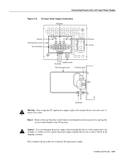
...14 shows a Cisco 4000 series router with the 1993 National Electric Code (NEC) and other applicable codes. Note The installation must comply with an AC-input power supply. To ensure that services the DC circuit, switch the circuit breaker to the OFF position, and tape the switch handle of protocol ...that power is OFF, locate the circuit breaker on the panel board that all power is removed from the DC circuit. If you ordered a Cisco 4000 series router with a DC-input power supply; Installing the Router 3-19 Connecting Routers with a DC-Input Power Supply Step 6 Configure the ...
...14 shows a Cisco 4000 series router with the 1993 National Electric Code (NEC) and other applicable codes. Note The installation must comply with an AC-input power supply. To ensure that services the DC circuit, switch the circuit breaker to the OFF position, and tape the switch handle of protocol ...that power is OFF, locate the circuit breaker on the panel board that all power is removed from the DC circuit. If you ordered a Cisco 4000 series router with a DC-input power supply; Installing the Router 3-19 Connecting Routers with a DC-Input Power Supply Step 6 Configure the ...
Hardware Maintenance Manual
Page 79
... occurs), remove the power supply terminal block cover so that it will fit in the shipping container. Step 4 Remove the tape from the circuit breaker switch handle and restore power by moving the circuit breaker handle to the ON position.
... occurs), remove the power supply terminal block cover so that it will fit in the shipping container. Step 4 Remove the tape from the circuit breaker switch handle and restore power by moving the circuit breaker handle to the ON position.

Hardware Maintenance Manual
Page 80
... acceptable range (200W, 85 to 264 VAC, 50 to 60 Hz). Step 2 Turn ON the system power switch. Making Final Connections to the Router Making Final Connections to the appropriate software publications. 3-22 Cisco 4000 Series Hardware Installation and Maintenance Follow this procedure to make the final connections to the router: Step...
... acceptable range (200W, 85 to 264 VAC, 50 to 60 Hz). Step 2 Turn ON the system power switch. Making Final Connections to the Router Making Final Connections to the appropriate software publications. 3-22 Cisco 4000 Series Hardware Installation and Maintenance Follow this procedure to make the final connections to the router: Step...
Hardware Maintenance Manual
Page 82
...most difficult to troubleshoot. Check the external cables for connection. • System will not initialize. - Suspect the processor or software. 4-2 Cisco 4000 Series Hardware Installation and Maintenance If no , suspect the AC input, AC source, router circuit breaker, or the power supply cable....Network Processor Modules and Cables Check for Installation" and ensure that connect the router to help isolate the problem: • With the power switch on, does the blower operate? - Check the network processor module connection to help identify a failure. Check the LEDs on the network...
...most difficult to troubleshoot. Check the external cables for connection. • System will not initialize. - Suspect the processor or software. 4-2 Cisco 4000 Series Hardware Installation and Maintenance If no , suspect the AC input, AC source, router circuit breaker, or the power supply cable....Network Processor Modules and Cables Check for Installation" and ensure that connect the router to help isolate the problem: • With the power switch on, does the blower operate? - Check the network processor module connection to help identify a failure. Check the LEDs on the network...
Hardware Maintenance Manual
Page 85
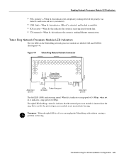
... the system is sending Ethernet transmissions. Timesaver When the right LED is receiving data from the line. • TX (transmit)-When lit, this indicates the autopolarity reading detected the polarity was defective and corrected for it (switched it indicates a ring speed of 4 Mbps. Token Ring Network Processor Module LED Indicators The two...
... the system is sending Ethernet transmissions. Timesaver When the right LED is receiving data from the line. • TX (transmit)-When lit, this indicates the autopolarity reading detected the polarity was defective and corrected for it (switched it indicates a ring speed of 4 Mbps. Token Ring Network Processor Module LED Indicators The two...
Hardware Maintenance Manual
Page 90
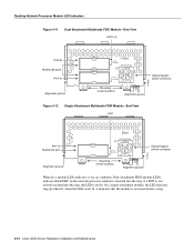
... View LEDs (2) PHY-B Multimode ports PHY-A Alignment groove PHY-B PHY-A PHY-B RING OP FDDI OPT-BYPASS PHY-A RING OP Optical bypass switch connector H1400a Mounting screw locations Alignment groove Figure 4-12 Single-Attachment Multimode FDDI Module-End View LED PHY-S Multimode port Alignment groove PHY-S FDDI... Alignment groove When lit, a module LED indicates a ring up when lit; if a PHY is not inserted into a ring. 4-10 Cisco 4000 Series Hardware Installation and Maintenance when the LED is not lit, it indicates that the module is not actively inserted into the ring; On...
... View LEDs (2) PHY-B Multimode ports PHY-A Alignment groove PHY-B PHY-A PHY-B RING OP FDDI OPT-BYPASS PHY-A RING OP Optical bypass switch connector H1400a Mounting screw locations Alignment groove Figure 4-12 Single-Attachment Multimode FDDI Module-End View LED PHY-S Multimode port Alignment groove PHY-S FDDI... Alignment groove When lit, a module LED indicates a ring up when lit; if a PHY is not inserted into a ring. 4-10 Cisco 4000 Series Hardware Installation and Maintenance when the LED is not lit, it indicates that the module is not actively inserted into the ring; On...
Hardware Maintenance Manual
Page 118
...the next reload, enter the show version EXEC command, and the value will be displayed on or when you switch the power off and on the last line of the screen display as in the following : config-register 0xvalue (The virtual configuration register is stored in nonvolatile...5 To display the configuration register value currently in effect and the value that are stored in its configuration file in NVRAM. B-2 Cisco 4000 Series Hardware Installation and Maintenance Virtual Configuration Register Settings Changing Configuration Register Settings Some common reasons to modify the value of the ...
...the next reload, enter the show version EXEC command, and the value will be displayed on or when you switch the power off and on the last line of the screen display as in the following : config-register 0xvalue (The virtual configuration register is stored in nonvolatile...5 To display the configuration register value currently in effect and the value that are stored in its configuration file in NVRAM. B-2 Cisco 4000 Series Hardware Installation and Maintenance Virtual Configuration Register Settings Changing Configuration Register Settings Some common reasons to modify the value of the ...
Hardware Maintenance Manual
Page 138
...media-type 2-10, 4-4 meminfo D-4 o (display virtual configuration register) C-3 o/r (reset) C-3 reload B-2 reset D-3 ROM monitor diagnostics Cisco 4000-M C-1 Cisco 4500-M D-1 Cisco 4700 D-1 setup 3-22 show version B-2 stack D-4 sysret D-4 t (test) C-3 terminal padding 3-2 component tray layout 5-5 config-register ...Cisco 4700 D-4 displaying settings C-3 resetting C-3 confreg command D-4 connections 10BaseT 2-10 9-pin D-type 3-2 auxiliary port 2-9 considerations when making 2-10 console port 2-9 Ethernet attaching to network 3-3 port, considerations 2-12 final 3-22 NT1 3-6 optical bypass switch...
...media-type 2-10, 4-4 meminfo D-4 o (display virtual configuration register) C-3 o/r (reset) C-3 reload B-2 reset D-3 ROM monitor diagnostics Cisco 4000-M C-1 Cisco 4500-M D-1 Cisco 4700 D-1 setup 3-22 show version B-2 stack D-4 sysret D-4 t (test) C-3 terminal padding 3-2 component tray layout 5-5 config-register ...Cisco 4700 D-4 displaying settings C-3 resetting C-3 confreg command D-4 connections 10BaseT 2-10 9-pin D-type 3-2 auxiliary port 2-9 considerations when making 2-10 console port 2-9 Ethernet attaching to network 3-3 port, considerations 2-12 final 3-22 NT1 3-6 optical bypass switch...


