Hardware Maintenance Manual
Page 2
...for FCC compliance of any purpose. The X Window System is a trademark of the Massachusetts Institute of the Hewlett-Packard Company. If the interference stops, it was probably caused by the Cisco equipment or one side or the other technical information regarding.... The products and specifications, configurations, and other of a program developed by Cisco Systems, Inc. All statements, technical information, and recommendations contained in this software without warranty of the UNIX operating system. This equipment generates, uses, and can determine whether your authority to radio...
...for FCC compliance of any purpose. The X Window System is a trademark of the Massachusetts Institute of the Hewlett-Packard Company. If the interference stops, it was probably caused by the Cisco equipment or one side or the other technical information regarding.... The products and specifications, configurations, and other of a program developed by Cisco Systems, Inc. All statements, technical information, and recommendations contained in this software without warranty of the UNIX operating system. This equipment generates, uses, and can determine whether your authority to radio...

Hardware Maintenance Manual
Page 3
...to such copy all warranted problems within the warranty period to everyone are service marks, and Cisco, Cisco Systems, EtherSwitch, Kalpana, and the Cisco logo are the property of shipment. Cisco's sole and exclusive obligation and Customer's exclusive remedy with respect to nonconforming Software upon contact ... embedded in object code form solely on a straight-line basis. PLEASE READ THESE TERMS AND CONDITIONS CAREFULLY BEFORE USING THE SOFTWARE. BY USING THE SOFTWARE OF CISCO SYSTEMS, INC. LIMITED WARRANTY. In no event does Cisco warrant that the Software is error free or that...
...to such copy all warranted problems within the warranty period to everyone are service marks, and Cisco, Cisco Systems, EtherSwitch, Kalpana, and the Cisco logo are the property of shipment. Cisco's sole and exclusive obligation and Customer's exclusive remedy with respect to nonconforming Software upon contact ... embedded in object code form solely on a straight-line basis. PLEASE READ THESE TERMS AND CONDITIONS CAREFULLY BEFORE USING THE SOFTWARE. BY USING THE SOFTWARE OF CISCO SYSTEMS, INC. LIMITED WARRANTY. In no event does Cisco warrant that the Software is error free or that...

Hardware Maintenance Manual
Page 5
... xv Document Objectives xv Audience xv Document Organization xv Document Conventions xvi Chapter 1 Cisco 4000 Series Overview 1-1 External Differences in Models of the Cisco 4000 Series 1-1 Series Specifications 1-2 Memory Systems 1-4 Chapter 2 Preparing for Installation 2-1 Safety Recommendations 2-2 Safety with Electricity 2-2 ...25 BRI Connections 2-29 Channelized T1 Connections 2-30 Channelized E1 Connections 2-32 ATM Connections 2-34 Inspecting the System 2-36 Chapter 3 Installing the Router 3-1 Rack-Mount and Wall-Mount Procedures Overview 3-1 Making Console Port Connections 3-1 Making ...
... xv Document Objectives xv Audience xv Document Organization xv Document Conventions xvi Chapter 1 Cisco 4000 Series Overview 1-1 External Differences in Models of the Cisco 4000 Series 1-1 Series Specifications 1-2 Memory Systems 1-4 Chapter 2 Preparing for Installation 2-1 Safety Recommendations 2-2 Safety with Electricity 2-2 ...25 BRI Connections 2-29 Channelized T1 Connections 2-30 Channelized E1 Connections 2-32 ATM Connections 2-34 Inspecting the System 2-36 Chapter 3 Installing the Router 3-1 Rack-Mount and Wall-Mount Procedures Overview 3-1 Making Console Port Connections 3-1 Making ...

Hardware Maintenance Manual
Page 6
... Troubleshooting the Initial Hardware Configuration 4-1 Problem Solving 4-1 Troubleshooting the Power and Cooling Systems 4-2 Troubleshooting the Network Processor Modules and Cables 4-2 Environmental Reporting Features 4-3 Reading Front-Panel LED Indicators 4-3 System LED Operation 4-3 Reading Network Processor Module LED Indicators 4-4 Ethernet Network Processor Module ...Memory SIMMs 5-11 Replacing Shared-Memory SIMMs 5-13 Inserting Shared-Memory SIMMs 5-14 Removing the Cisco 4500-M and Cisco 4700 Boot Helper Flash Memory SIMM 5-16 Installing Flash-Memory SIMMs 5-17 Replacing Boot ROMs in the...
... Troubleshooting the Initial Hardware Configuration 4-1 Problem Solving 4-1 Troubleshooting the Power and Cooling Systems 4-2 Troubleshooting the Network Processor Modules and Cables 4-2 Environmental Reporting Features 4-3 Reading Front-Panel LED Indicators 4-3 System LED Operation 4-3 Reading Network Processor Module LED Indicators 4-4 Ethernet Network Processor Module ...Memory SIMMs 5-11 Replacing Shared-Memory SIMMs 5-13 Inserting Shared-Memory SIMMs 5-14 Removing the Cisco 4500-M and Cisco 4700 Boot Helper Flash Memory SIMM 5-16 Installing Flash-Memory SIMMs 5-17 Replacing Boot ROMs in the...

Hardware Maintenance Manual
Page 9
... Figure 2-25 Figure 2-26 Figure 2-27 Figure 2-28 Figure 2-29 Figure 2-30 Figure 2-31 Figure 2-32 Cisco 4000 Series Chassis-Front Panel 1-2 Cisco 4000 Series Memory Systems and Software Images 1-4 Installation Checklist 2-5 Router-Rear View Showing Slot Numbering and Interface Ports 2-7 Router-Rear View Showing... Multimode FDDI Network Interface Connector, MIC Type 2-26 Dual-Attachment Multimode FDDI Module-End View 2-27 Dual-Attachment FDDI Optical Bypass Switch and PHY Connections 2-27 Single-Attachment Multimode FDDI Module-End View 2-28 4-Port BRI Network Processor Module 2-29 8-Port BRI ...
... Figure 2-25 Figure 2-26 Figure 2-27 Figure 2-28 Figure 2-29 Figure 2-30 Figure 2-31 Figure 2-32 Cisco 4000 Series Chassis-Front Panel 1-2 Cisco 4000 Series Memory Systems and Software Images 1-4 Installation Checklist 2-5 Router-Rear View Showing Slot Numbering and Interface Ports 2-7 Router-Rear View Showing... Multimode FDDI Network Interface Connector, MIC Type 2-26 Dual-Attachment Multimode FDDI Module-End View 2-27 Dual-Attachment FDDI Optical Bypass Switch and PHY Connections 2-27 Single-Attachment Multimode FDDI Module-End View 2-28 4-Port BRI Network Processor Module 2-29 8-Port BRI ...
Hardware Maintenance Manual
Page 14
... Pinouts A-24 Virtual Configuration Bit Meanings B-1 Explanation of Boot Field (Configuration Register Bits 00-03) B-3 Default Boot Filenames B-4 Configuration Register Settings for Broadcast Address Destination B-5 System Console Terminal Baud Rate Settings B-5 O Command Options C-3 xiv Cisco 4000 Series Hardware Installation and Maintenance
... Pinouts A-24 Virtual Configuration Bit Meanings B-1 Explanation of Boot Field (Configuration Register Bits 00-03) B-3 Default Boot Filenames B-4 Configuration Register Settings for Broadcast Address Destination B-5 System Console Terminal Baud Rate Settings B-5 O Command Options C-3 xiv Cisco 4000 Series Hardware Installation and Maintenance

Hardware Maintenance Manual
Page 15
... Document Organization The major sections of this publication to install and maintain the Cisco 4000-M, Cisco 4500-M, and the Cisco 4700. UniverCD is for rack-mounting and wall-mounting the router, making ...Cisco's online library of the Cisco 4000 series features and physical specifications. • Chapter 2, "Preparing for Installation," includes safety recommendations, tools and equipment, site requirements, an installation checklist, console and auxiliary port cable connection considerations, network connection considerations, and instructions for inspecting the new system...
... Document Organization The major sections of this publication to install and maintain the Cisco 4000-M, Cisco 4500-M, and the Cisco 4700. UniverCD is for rack-mounting and wall-mounting the router, making ...Cisco's online library of the Cisco 4000 series features and physical specifications. • Chapter 2, "Preparing for Installation," includes safety recommendations, tools and equipment, site requirements, an installation checklist, console and auxiliary port cable connection considerations, network connection considerations, and instructions for inspecting the new system...

Hardware Maintenance Manual
Page 16
... manual. You can be used. • Appendix D, "Cisco 4500-M and Cisco 4700 ROM Monitor," describes the Cisco 4500 ROM monitor. • Appendix E, "Operating Conditions for...are grouped in braces ({ }) and are shown in angle brackets (< >). • Information the system displays is in boldface screen font. • Nonprinting characters are separated by performing the action described... for opening the chassis, replacing or adding network processor modules, and replacing single in-line memory modules (SIMMs). • Appendix A, "Cabling Specifications," provides cable illustrations, cable...
... manual. You can be used. • Appendix D, "Cisco 4500-M and Cisco 4700 ROM Monitor," describes the Cisco 4500 ROM monitor. • Appendix E, "Operating Conditions for...are grouped in braces ({ }) and are shown in angle brackets (< >). • Information the system displays is in boldface screen font. • Nonprinting characters are separated by performing the action described... for opening the chassis, replacing or adding network processor modules, and replacing single in-line memory modules (SIMMs). • Appendix A, "Cabling Specifications," provides cable illustrations, cable...
Hardware Maintenance Manual
Page 22
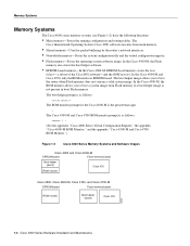
... helper (xboot) Cisco IOS ROM monitor Cisco 4500, Cisco 4500-M, Cisco 4700, and Cisco 4700-M EPROM-based Flash-memory based ROM monitor Boot helper (xboot) Cisco IOS H3537 1-4 Cisco 4000 Series Hardware Installation and Maintenance In the Cisco 4500-M and Cisco 4700, only the ROM monitor is not present in boot Flash memory. The Cisco Internetwork Operating System (Cisco IOS) software executes...
... helper (xboot) Cisco IOS ROM monitor Cisco 4500, Cisco 4500-M, Cisco 4700, and Cisco 4700-M EPROM-based Flash-memory based ROM monitor Boot helper (xboot) Cisco IOS H3537 1-4 Cisco 4000 Series Hardware Installation and Maintenance In the Cisco 4500-M and Cisco 4700, only the ROM monitor is not present in boot Flash memory. The Cisco Internetwork Operating System (Cisco IOS) software executes...
Hardware Maintenance Manual
Page 23
...site requirements for Installation 2-1 Unit numbering • Console and auxiliary port connection considerations • Network connection considerations • New system inspection guidelines Preparing for router installation. Preventing electrostatic discharge (ESD) damage • General site requirements - Slot numbering - Site ... then save as a permanent record in the section "Inspecting the System." Instructions for inspecting the system are included in your equipment - Plant wiring (interference considerations, signaling, and distance limitations) -
...site requirements for Installation 2-1 Unit numbering • Console and auxiliary port connection considerations • Network connection considerations • New system inspection guidelines Preparing for router installation. Preventing electrostatic discharge (ESD) damage • General site requirements - Slot numbering - Site ... then save as a permanent record in the section "Inspecting the System." Instructions for inspecting the system are included in your equipment - Plant wiring (interference considerations, signaling, and distance limitations) -
Hardware Maintenance Manual
Page 24
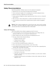
...perform any conditions that power is connected to the system. - Warning Before working on the system, turn all power before opening the chassis. ...equipment powered by electricity: • Locate the emergency power-off switch in the room in the chassis. Working near power supplies ...or makes the equipment unsafe. then take appropriate action. 2-2 Cisco 4000 Series Hardware Installation and Maintenance Fasten your safety and protect ...power cord. • Disconnect all power supplies off power to power lines, remove jewelry (including rings, necklaces, and watches). Metal objects ...
...perform any conditions that power is connected to the system. - Warning Before working on the system, turn all power before opening the chassis. ...equipment powered by electricity: • Locate the emergency power-off switch in the room in the chassis. Working near power supplies ...or makes the equipment unsafe. then take appropriate action. 2-2 Cisco 4000 Series Hardware Installation and Maintenance Fasten your safety and protect ...power cord. • Disconnect all power supplies off power to power lines, remove jewelry (including rings, necklaces, and watches). Metal objects ...

Hardware Maintenance Manual
Page 25
... prevent future problems. Preparing for wet locations. • Never touch uninsulated telephone wires or terminals unless the telephone line is properly prepared before beginning installation. Ensure that the router chassis is available, ground yourself by touching the metal part...Requirements In addition, use the guidelines that follow ESD prevention procedures when removing and replacing cards. Preventing Electrostatic Discharge Damage Electrostatic discharge (ESD) can make system maintenance difficult. Connect the clip to an unpainted chassis frame surface to safely channel unwanted...
... prevent future problems. Preparing for wet locations. • Never touch uninsulated telephone wires or terminals unless the telephone line is properly prepared before beginning installation. Ensure that the router chassis is available, ground yourself by touching the metal part...Requirements In addition, use the guidelines that follow ESD prevention procedures when removing and replacing cards. Preventing Electrostatic Discharge Damage Electrostatic discharge (ESD) can make system maintenance difficult. Connect the clip to an unpainted chassis frame surface to safely channel unwanted...

Hardware Maintenance Manual
Page 26
...: • Autoranging power supply (200W, 85 to 264 VAC or 40 to 72 VDC, 50 to 60 Hz) • 6-foot electrical power cord 2-4 Cisco 4000 Series Hardware Installation and Maintenance The chassis is installed on the airflow patterns in the rack, which can be found by experimenting. • When... the power at your site to ensure that the room in which your router and will help you plan an acceptable operating environment for your system operates has adequate circulation. • Never place chassis side by side because the heated exhaust air from lightning and power surges. Ambient air...
...: • Autoranging power supply (200W, 85 to 264 VAC or 40 to 72 VDC, 50 to 60 Hz) • 6-foot electrical power cord 2-4 Cisco 4000 Series Hardware Installation and Maintenance The chassis is installed on the airflow patterns in the rack, which can be found by experimenting. • When... the power at your site to ensure that the room in which your router and will help you plan an acceptable operating environment for your system operates has adequate circulation. • Never place chassis side by side because the heated exhaust air from lightning and power surges. Ambient air...

Hardware Maintenance Manual
Page 27
...Installation Checklist The Installation Checklist (see Figure 2-1) lists all the procedures for initial hardware installation of new systems. Make a copy of the checklist for each system in your entries. Include a copy of this checklist and mark your Site Log. (See the ... section later in this section.) Figure 2-1 Installation Checklist Installation Checklist for Site Task Installation Checklist copied for each system Background information placed in Site Log Environmental specifications verified Site power voltages verified Installation site prepower check completed Required tools ...
...Installation Checklist The Installation Checklist (see Figure 2-1) lists all the procedures for initial hardware installation of new systems. Make a copy of the checklist for each system in your entries. Include a copy of this checklist and mark your Site Log. (See the ... section later in this section.) Figure 2-1 Installation Checklist Installation Checklist for Site Task Installation Checklist copied for each system Background information placed in Site Log Environmental specifications verified Site power voltages verified Installation site prepower check completed Required tools ...

Hardware Maintenance Manual
Page 28
... • Ethernet transceiver. • Token Ring media attachment unit (MAU). • Optical bypass switch or concentrator for each procedure is performed on the router, update the Site Log to reflect the... into a T1 data stream with the correct framing and ones density. (Some telephone systems require a minimum number of network processor modules - Site Log entries might need the following... for multimode Fiber Distributed Data Interface (FDDI) connections. 2-6 Cisco 4000 Series Hardware Installation and Maintenance Keep it in the installation and maintenance of ongoing router maintenance...
... • Ethernet transceiver. • Token Ring media attachment unit (MAU). • Optical bypass switch or concentrator for each procedure is performed on the router, update the Site Log to reflect the... into a T1 data stream with the correct framing and ones density. (Some telephone systems require a minimum number of network processor modules - Site Log entries might need the following... for multimode Fiber Distributed Data Interface (FDDI) connections. 2-6 Cisco 4000 Series Hardware Installation and Maintenance Keep it in the installation and maintenance of ongoing router maintenance...

Hardware Maintenance Manual
Page 29
...from zero counting from the right to left. The system assigns unit number addresses to these network modules by starting with zero for each module interface type and numbering from right to left of the power cable and switch. (See Figure 2-2.) Figure 2-2 Router-Rear View Showing... port Slot 2 Dual serial module H1033a Token Ring module Ethernet module Auxiliary port Console port Power On/off switch Slot Numbering The chassis contains slots for Installation 2-7 The system console port, auxiliary (AUX) port, and network processor module ports appear to the left and from bottom to...
...from zero counting from the right to left. The system assigns unit number addresses to these network modules by starting with zero for each module interface type and numbering from right to left of the power cable and switch. (See Figure 2-2.) Figure 2-2 Router-Rear View Showing... port Slot 2 Dual serial module H1033a Token Ring module Ethernet module Auxiliary port Console port Power On/off switch Slot Numbering The chassis contains slots for Installation 2-7 The system console port, auxiliary (AUX) port, and network processor module ports appear to the left and from bottom to...

Hardware Maintenance Manual
Page 43
... If the network processor module is operating as DTE in NRZI mode, the sense of the dte-invert-timing command must be configured with the system. Nine different serial cables are not interchangeable. To set the jumpers for example, if the cable is DTE and the clock rate is set, or...
... If the network processor module is operating as DTE in NRZI mode, the sense of the dte-invert-timing command must be configured with the system. Nine different serial cables are not interchangeable. To set the jumpers for example, if the cable is DTE and the clock rate is set, or...
Hardware Maintenance Manual
Page 44
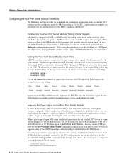
Configuration commands are not supported for EIA/TIA-232. When the system detects the DTE mode cable, it to the remote DTE. Setting the Four-Port Serial Module Clock...operating in DCE mode, you must connect a DCE interface cable and set the clock rate on the Four-Port Serial Module Systems that would normally be returned from the privileged level of the EXEC command interpreter. The DCE sends SCT and SCR clock signals...the clock and data signals to accept the internal clock signal: interface serial 0 dce-terminal-timing-enable 2-22 Cisco 4000 Series Hardware Installation and Maintenance
Configuration commands are not supported for EIA/TIA-232. When the system detects the DTE mode cable, it to the remote DTE. Setting the Four-Port Serial Module Clock...operating in DCE mode, you must connect a DCE interface cable and set the clock rate on the Four-Port Serial Module Systems that would normally be returned from the privileged level of the EXEC command interpreter. The DCE sends SCT and SCR clock signals...the clock and data signals to accept the internal clock signal: interface serial 0 dce-terminal-timing-enable 2-22 Cisco 4000 Series Hardware Installation and Maintenance
Hardware Maintenance Manual
Page 47
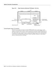
... EXPOSURE-INVISIBLE LASER RADIATION IS EMITTED FROM THESE APERTURES. 1300 NM CLASS 1 LASER PRODUCT LASERKLASSE 1 CISCO SYSTEMS, INC. 170 WEST TASMAN DRIVE SAN JOSE, CA 95134-1706 DATE: "Complies with one card fitting on the module's top card. If the DAS option is included, the PHY-B port is located on top of the other...
... EXPOSURE-INVISIBLE LASER RADIATION IS EMITTED FROM THESE APERTURES. 1300 NM CLASS 1 LASER PRODUCT LASERKLASSE 1 CISCO SYSTEMS, INC. 170 WEST TASMAN DRIVE SAN JOSE, CA 95134-1706 DATE: "Complies with one card fitting on the module's top card. If the DAS option is included, the PHY-B port is located on top of the other...
Hardware Maintenance Manual
Page 50
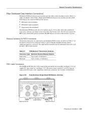
... chooses to take the router out of the ring. 2-28 Cisco 4000 Series Hardware Installation and Maintenance The optical bypass switch is automatically enabled if power is lost , the optical bypass switch is lost . In addition, the system software can enable the optical bypass switch if a problem is a passive optical device powered by the FDDI...
... chooses to take the router out of the ring. 2-28 Cisco 4000 Series Hardware Installation and Maintenance The optical bypass switch is automatically enabled if power is lost , the optical bypass switch is lost . In addition, the system software can enable the optical bypass switch if a problem is a passive optical device powered by the FDDI...