
Hardware Maintenance Manual
Page 28
..., and most provide either a V.35, EIA/TIA-449, or EIA-530 electrical interface. • Ethernet transceiver. • Token Ring media attachment unit (MAU). • Optical bypass switch or concentrator for multimode Fiber Distributed Data Interface (FDDI) connections. 2-6 Cisco 4000 Series Hardware Installation and Maintenance Configuration changes - Use the Installation Checklist to reflect the...
..., and most provide either a V.35, EIA/TIA-449, or EIA-530 electrical interface. • Ethernet transceiver. • Token Ring media attachment unit (MAU). • Optical bypass switch or concentrator for multimode Fiber Distributed Data Interface (FDDI) connections. 2-6 Cisco 4000 Series Hardware Installation and Maintenance Configuration changes - Use the Installation Checklist to reflect the...
Hardware Maintenance Manual
Page 33
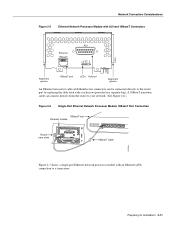
... with AUI and 10BaseT Connectors AUI Ethernet 10BaseT TX RX LNK POL AUI H1043a Alignment groove 10BaseT port LEDs AUI port Alignment groove An Ethernet transceiver cable with a jackscrew (provided in a separate bag). A 10BaseT transition cable can connect directly from the router to your network. (See Figure 2-6.) Figure 2-6 Single-Port Ethernet... network processor module with an Ethernet (AUI) connection to the router port by replacing the slide latch with thumbscrew connectors can be connected directly to a transceiver.
... with AUI and 10BaseT Connectors AUI Ethernet 10BaseT TX RX LNK POL AUI H1043a Alignment groove 10BaseT port LEDs AUI port Alignment groove An Ethernet transceiver cable with a jackscrew (provided in a separate bag). A 10BaseT transition cable can connect directly from the router to your network. (See Figure 2-6.) Figure 2-6 Single-Port Ethernet... network processor module with an Ethernet (AUI) connection to the router port by replacing the slide latch with thumbscrew connectors can be connected directly to a transceiver.
Hardware Maintenance Manual
Page 34
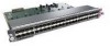
...module, and the lower port is marked Port-1 on a given port, either a 10BaseT connector or to an AUI connector. 2-12 Cisco 4000 Series Hardware Installation and Maintenance For example, Ethernet port 0 could be attached to either a 10BaseT connector or to an AUI connector...-inch transition cable. Network Connection Considerations Router (rear view) Figure 2-7 Single-Port Ethernet Network Processor Module AUI Port Connection Ethernet module Transceiver Slide-latch connector H1525a AUI Router (rear view) AUX 18" transition cable Figure 2-8 shows the transition cable used , but not both...
...module, and the lower port is marked Port-1 on a given port, either a 10BaseT connector or to an AUI connector. 2-12 Cisco 4000 Series Hardware Installation and Maintenance For example, Ethernet port 0 could be attached to either a 10BaseT connector or to an AUI connector...-inch transition cable. Network Connection Considerations Router (rear view) Figure 2-7 Single-Port Ethernet Network Processor Module AUI Port Connection Ethernet module Transceiver Slide-latch connector H1525a AUI Router (rear view) AUX 18" transition cable Figure 2-8 shows the transition cable used , but not both...
Hardware Maintenance Manual
Page 47
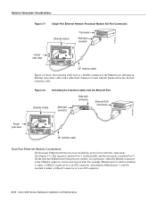
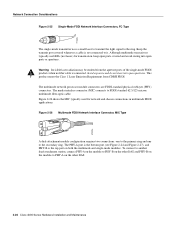
...1300 NM CLASS 1 LASER PRODUCT LASERKLASSE 1 CISCO SYSTEMS, INC. 170 WEST TASMAN DRIVE SAN JOSE, CA 95134-1706 DATE: "Complies with one card fitting on the module's top card. Network Connection Considerations Fiber Distributed Data Interface ...Connections Multimode FDDI network processor modules provide either a dual-attachment station (DAS) or a single-attachment station (SAS). The single-mode transmitter and the multimode transceiver each with a multimode transceiver...
...1300 NM CLASS 1 LASER PRODUCT LASERKLASSE 1 CISCO SYSTEMS, INC. 170 WEST TASMAN DRIVE SAN JOSE, CA 95134-1706 DATE: "Complies with one card fitting on the module's top card. Network Connection Considerations Fiber Distributed Data Interface ...Connections Multimode FDDI network processor modules provide either a dual-attachment station (DAS) or a single-attachment station (SAS). The single-mode transmitter and the multimode transceiver each with a multimode transceiver...
Hardware Maintenance Manual
Page 48
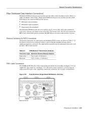
.... To connect to another dual-attachment station, connect PHY-A on the module to PHY-B on the other DAS. 2-26 Cisco 4000 Series Hardware Installation and Maintenance H1349a The multimode network processor module connectors are FDDI-standard physical sublayer (PHY) connectors. The... media interface connector (MIC) connects to PHY-A on both the multimode and single-mode modules. Although multimode transceivers typically use LEDs (not lasers) for network and chassis connections in multimode FDDI applications. This product meets the Class 1 Laser Emission...
.... To connect to another dual-attachment station, connect PHY-A on the module to PHY-B on the other DAS. 2-26 Cisco 4000 Series Hardware Installation and Maintenance H1349a The multimode network processor module connectors are FDDI-standard physical sublayer (PHY) connectors. The... media interface connector (MIC) connects to PHY-A on both the multimode and single-mode modules. Although multimode transceivers typically use LEDs (not lasers) for network and chassis connections in multimode FDDI applications. This product meets the Class 1 Laser Emission...
Hardware Maintenance Manual
Page 61
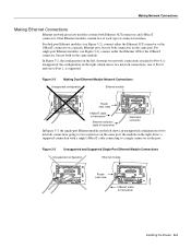
...Unsupported configuration Ethernet module AUI AUI AUI Router AUI (rear view) H1571a AUX 10BaseT cable AUX to transceiver Slide-latch Ethernet transition connector cable to transceiver In Figure 3-3, the single-port Ethernet module on the left , showing two network connections attached ...single 10BaseT cable connecting to a single connector on the right, which shows two network connections, one to Port 0 and one to transceiver Installing the Router 3-3 the configuration on the port. For single-port Ethernet modules (see Figure 3-2), connect either the Ethernet AUI or...
...Unsupported configuration Ethernet module AUI AUI AUI Router AUI (rear view) H1571a AUX 10BaseT cable AUX to transceiver Slide-latch Ethernet transition connector cable to transceiver In Figure 3-3, the single-port Ethernet module on the left , showing two network connections attached ...single 10BaseT cable connecting to a single connector on the right, which shows two network connections, one to Port 0 and one to transceiver Installing the Router 3-3 the configuration on the port. For single-port Ethernet modules (see Figure 3-2), connect either the Ethernet AUI or...
Hardware Maintenance Manual
Page 62
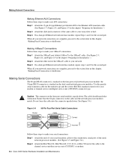
...Figure 2-8, and Figure 2-9 in this chapter, "Making Final Connections to the Router." Step 1 Attach the ends of the same cable to make your transceiver or hub. Step 3 On a dual-port Ethernet network interface module, repeat steps 1 and 2 for Installation.") Step 2 Attach the slide-latch ...and Figure 2-9 in this chapter, "Making Final Connections to the channel service unit/data service unit (CSU/DSU) or modem. 3-4 Cisco 4000 Series Hardware Installation and Maintenance Use the specific serial transition cable for the module type and the correct EIA/TIA standard connector for ...
...Figure 2-8, and Figure 2-9 in this chapter, "Making Final Connections to the Router." Step 1 Attach the ends of the same cable to make your transceiver or hub. Step 3 On a dual-port Ethernet network interface module, repeat steps 1 and 2 for Installation.") Step 2 Attach the slide-latch ...and Figure 2-9 in this chapter, "Making Final Connections to the channel service unit/data service unit (CSU/DSU) or modem. 3-4 Cisco 4000 Series Hardware Installation and Maintenance Use the specific serial transition cable for the module type and the correct EIA/TIA standard connector for ...
Hardware Maintenance Manual
Page 75
... 11 Check the interface configuration with show a basic ATM configuration using just PVCs. After you must enter the configuration mode. The following information: • ATM transceiver framing type (STS-3c or STM-1), • Network protocol addresses, • PVC connections and their attributes, • Static address mappings (address-lists). Step 10 Exit...
... 11 Check the interface configuration with show a basic ATM configuration using just PVCs. After you must enter the configuration mode. The following information: • ATM transceiver framing type (STS-3c or STM-1), • Network protocol addresses, • PVC connections and their attributes, • Static address mappings (address-lists). Step 10 Exit...
Hardware Maintenance Manual
Page 137
...Cisco 4500-M D-3 Cisco 4700 D-3 bootstrap clear memory contents C-2 stack trace, system software C-2 Break key (interrupt) C-1, D-1 BRI distance limitations 2-30, 3-6 making connections to 3-6 network hazardous voltage warning 3-6 pinout 3-8, A-22 C c command (continue) C-2 cable 10BaseT 2-10 assemblies A-2-A-21 ATM 2-35 BRI A-22 CE1 A-23 console port, pinout A-2 CT1 2-31, A-22 Ethernet transceiver...to connect 2-21 single-mode fiber optic 2-25 specifications A-1 Token Ring lobe 2-14 transceiver 2-11 cables safety guidelines 2-3 ungrounded 2-3 uninsulated 2-3 caution, description xvii CE1 cable ...
...Cisco 4500-M D-3 Cisco 4700 D-3 bootstrap clear memory contents C-2 stack trace, system software C-2 Break key (interrupt) C-1, D-1 BRI distance limitations 2-30, 3-6 making connections to 3-6 network hazardous voltage warning 3-6 pinout 3-8, A-22 C c command (continue) C-2 cable 10BaseT 2-10 assemblies A-2-A-21 ATM 2-35 BRI A-22 CE1 A-23 console port, pinout A-2 CT1 2-31, A-22 Ethernet transceiver...to connect 2-21 single-mode fiber optic 2-25 specifications A-1 Token Ring lobe 2-14 transceiver 2-11 cables safety guidelines 2-3 ungrounded 2-3 uninsulated 2-3 caution, description xvii CE1 cable ...
Hardware Maintenance Manual
Page 143
... 4-3 problem indications 4-3 warning 4-3 terminal padding command 3-2 time saver, description xvi Token Ring connecting 3-2 connecting cable 3-2 connections 2-13 LED indications 4-5 port, location 2-7 tools required for installation 2-6 transceiver cable 2-11 transmit, Ethernet LED 4-5 tray, component, replacing 5-20 troubleshooting cables 4-2 initial hardware configuration 4-1 network processor modules 4-2 power and cooling systems 4-2 U unit numbering 2-7 United Kingdom...
... 4-3 problem indications 4-3 warning 4-3 terminal padding command 3-2 time saver, description xvi Token Ring connecting 3-2 connecting cable 3-2 connections 2-13 LED indications 4-5 port, location 2-7 tools required for installation 2-6 transceiver cable 2-11 transmit, Ethernet LED 4-5 tray, component, replacing 5-20 troubleshooting cables 4-2 initial hardware configuration 4-1 network processor modules 4-2 power and cooling systems 4-2 U unit numbering 2-7 United Kingdom...