
Hardware Maintenance Manual
Page 7
...19 Ethernet (AUI) Cable Pinouts A-19 RJ-45 10BaseT Connector Pinouts A-20 Token Ring Port Pinout A-21 BRI Pinout A-22 Channelized T1 Pinouts A-22 Channelized E1 Pinouts A-23 Appendix B Cisco 4000 Series Virtual Configuration Register B-1 Virtual Configuration Register Settings ... Configuring the Boot Field B-3 Enabling Booting from Flash Memory B-6 Appendix C Cisco 4000-M ROM Monitor C-1 Entering the Cisco 4000-M ROM Monitor Program C-1 Available ROM Monitor Commands C-2 Appendix D Cisco 4500-M and Cisco 4700 ROM Monitor D-1 Entering the ROM Monitor Program D-1 Available ROM Monitor ...
...19 Ethernet (AUI) Cable Pinouts A-19 RJ-45 10BaseT Connector Pinouts A-20 Token Ring Port Pinout A-21 BRI Pinout A-22 Channelized T1 Pinouts A-22 Channelized E1 Pinouts A-23 Appendix B Cisco 4000 Series Virtual Configuration Register B-1 Virtual Configuration Register Settings ... Configuring the Boot Field B-3 Enabling Booting from Flash Memory B-6 Appendix C Cisco 4000-M ROM Monitor C-1 Entering the Cisco 4000-M ROM Monitor Program C-1 Available ROM Monitor Commands C-2 Appendix D Cisco 4500-M and Cisco 4700 ROM Monitor D-1 Entering the ROM Monitor Program D-1 Available ROM Monitor ...

Hardware Maintenance Manual
Page 9
... 2-24 Figure 2-25 Figure 2-26 Figure 2-27 Figure 2-28 Figure 2-29 Figure 2-30 Figure 2-31 Figure 2-32 Cisco 4000 Series Chassis-Front Panel 1-2 Cisco 4000 Series Memory Systems and Software Images 1-4 Installation Checklist 2-5 Router-Rear View Showing Slot Numbering and Interface Ports 2-7 Router... Module-End View 2-25 Single-Mode FDDI Network Interface Connectors, FC Type 2-26 Multimode FDDI Network Interface Connector, MIC Type 2-26 Dual-Attachment Multimode FDDI Module-End View 2-27 Dual-Attachment FDDI Optical Bypass Switch and PHY Connections 2-27 Single-Attachment Multimode FDDI Module-...
... 2-24 Figure 2-25 Figure 2-26 Figure 2-27 Figure 2-28 Figure 2-29 Figure 2-30 Figure 2-31 Figure 2-32 Cisco 4000 Series Chassis-Front Panel 1-2 Cisco 4000 Series Memory Systems and Software Images 1-4 Installation Checklist 2-5 Router-Rear View Showing Slot Numbering and Interface Ports 2-7 Router... Module-End View 2-25 Single-Mode FDDI Network Interface Connectors, FC Type 2-26 Multimode FDDI Network Interface Connector, MIC Type 2-26 Dual-Attachment Multimode FDDI Module-End View 2-27 Dual-Attachment FDDI Optical Bypass Switch and PHY Connections 2-27 Single-Attachment Multimode FDDI Module-...

Hardware Maintenance Manual
Page 10
...View 3-20 DC-Input Power Supply Connections 3-21 Cisco 4000 Series-Front Panel Indicators 4-3 Dual-Port Ethernet Network Processor Module LEDs 4-4 Single-Port Ethernet Network Processor Module LEDs 4-4 Token Ring Module Network Connector 4-5 Four-Port Serial Network Processor Module Ports 4-6 ...G.703/G.704 Serial Network Processor Module Ports (DB-15) 4-6 Serial Port Labeled V2 4-7 Dual Serial Network Processor Module-Top View 4-8 Dual Serial Port LED Card-Side View 4-8 Dual-Attachment Single-Mode FDDI Module-End View 4-9 x Cisco...
...View 3-20 DC-Input Power Supply Connections 3-21 Cisco 4000 Series-Front Panel Indicators 4-3 Dual-Port Ethernet Network Processor Module LEDs 4-4 Single-Port Ethernet Network Processor Module LEDs 4-4 Token Ring Module Network Connector 4-5 Four-Port Serial Network Processor Module Ports 4-6 ...G.703/G.704 Serial Network Processor Module Ports (DB-15) 4-6 Serial Port Labeled V2 4-7 Dual Serial Network Processor Module-Top View 4-8 Dual Serial Port LED Card-Side View 4-8 Dual-Attachment Single-Mode FDDI Module-End View 4-9 x Cisco...

Hardware Maintenance Manual
Page 11
...Removal for Chassis With a Safety Latch 5-3 Component Tray Removal for Chassis Without a Safety Latch 5-4 Typical Cisco 4000 Series Component Tray-Cisco 4000-M Shown 5-5 Network Processor Module Locations 5-6 Cisco 4000-M SIMM Locations 5-7 Cisco 4500-M and Cisco 4700 SIMM Locations 5-8 Cisco 4000 Series Main Memory SIMM 5-8 Removing Main Memory SIMMs 5-10 Installing Main Memory SIMMs 5-12 Inserting... Module EIA-530 Cable Assembly A-16 Four-Port Serial Module EIA-530 Cable Assembly A-18 Ethernet (AUI) Cable Assembly A-19 RJ-45 10BaseT Connector A-20 T1 Interface Cable A-22 List of Figures xi
...Removal for Chassis With a Safety Latch 5-3 Component Tray Removal for Chassis Without a Safety Latch 5-4 Typical Cisco 4000 Series Component Tray-Cisco 4000-M Shown 5-5 Network Processor Module Locations 5-6 Cisco 4000-M SIMM Locations 5-7 Cisco 4500-M and Cisco 4700 SIMM Locations 5-8 Cisco 4000 Series Main Memory SIMM 5-8 Removing Main Memory SIMMs 5-10 Installing Main Memory SIMMs 5-12 Inserting... Module EIA-530 Cable Assembly A-16 Four-Port Serial Module EIA-530 Cable Assembly A-18 Ethernet (AUI) Cable Assembly A-19 RJ-45 10BaseT Connector A-20 T1 Interface Cable A-22 List of Figures xi

Hardware Maintenance Manual
Page 12
Figure A-14 Figure A-15 Figure A-16 Figure A-17 E1 Interface Cable for 75-Ohm, Unbalanced Connections (with BNC Connectors) A-23 E1 Interface Cable for 120-Ohm, Balanced Connections (with DB-15 Connectors) A-24 E1 Interface Cable for 120-Ohm, Balanced Connections (with Twinax Connectors) A-24 E1 Interface Cable for 120-Ohm, Balanced Connections (with RJ-45 Connector) A-24 xii Cisco 4000 Series Hardware Installation and Maintenance
Figure A-14 Figure A-15 Figure A-16 Figure A-17 E1 Interface Cable for 75-Ohm, Unbalanced Connections (with BNC Connectors) A-23 E1 Interface Cable for 120-Ohm, Balanced Connections (with DB-15 Connectors) A-24 E1 Interface Cable for 120-Ohm, Balanced Connections (with Twinax Connectors) A-24 E1 Interface Cable for 120-Ohm, Balanced Connections (with RJ-45 Connector) A-24 xii Cisco 4000 Series Hardware Installation and Maintenance

Hardware Maintenance Manual
Page 13
...Distances Based on Voltage 3-10 Four Port Serial Network Processor Module LED Indicators 4-7 Dual Serial Network Processor Module LED Indicators 4-9 Cisco 4000-M Console and Auxiliary Port Signals A-2 Cisco 4500-M and Cisco 4700 Console and Auxiliary Port Signals A-2 Dual Serial Module EIA/TIA-232 DTE and DCE Serial Cable Pinouts A-4 Four-Port... Pinout A-17 Four-Port Serial EIA-530 DTE Cable Pinout (DB-60 to DB-25) A-18 Ethernet (AUI) Pinout A-19 RJ-45 Connector Pinout A-20 Token Ring Port Pinout (DB-9 Connector) A-21 Dual-Port Token Ring Pinout (DB-9 Connector) A-21 A-11 List of Tables xiii
...Distances Based on Voltage 3-10 Four Port Serial Network Processor Module LED Indicators 4-7 Dual Serial Network Processor Module LED Indicators 4-9 Cisco 4000-M Console and Auxiliary Port Signals A-2 Cisco 4500-M and Cisco 4700 Console and Auxiliary Port Signals A-2 Dual Serial Module EIA/TIA-232 DTE and DCE Serial Cable Pinouts A-4 Four-Port... Pinout A-17 Four-Port Serial EIA-530 DTE Cable Pinout (DB-60 to DB-25) A-18 Ethernet (AUI) Pinout A-19 RJ-45 Connector Pinout A-20 Token Ring Port Pinout (DB-9 Connector) A-21 Dual-Port Token Ring Pinout (DB-9 Connector) A-21 A-11 List of Tables xiii

Hardware Maintenance Manual
Page 21
..., EIA/TIA-4491, V.35, X.21, NRZ/NRZI, DTE/DCE; The Orion microprocessor is based on the MIPS R4400 and is pin-compatible. 2. Cisco 4000 Series Overview 1-3 Table 1-1 Cisco 4000 Series Physical Specifications Description Design Specification Dimensions (W x D x H) 17.6" x 17.7" x 3.4" (44.7 cm x 45 cm x 8.6 cm.... Series Specifications Table 1-1 lists the physical specifications for the Cisco 4000 series routers. EIA-530 DTE Console Port EIA/TIA-232 DB-25 female connector Auxiliary Port EIA/TIA-232 DB-25 male connector Nonoperating Temperature -40 to 185°F (-40 to 85&#...
..., EIA/TIA-4491, V.35, X.21, NRZ/NRZI, DTE/DCE; The Orion microprocessor is based on the MIPS R4400 and is pin-compatible. 2. Cisco 4000 Series Overview 1-3 Table 1-1 Cisco 4000 Series Physical Specifications Description Design Specification Dimensions (W x D x H) 17.6" x 17.7" x 3.4" (44.7 cm x 45 cm x 8.6 cm.... Series Specifications Table 1-1 lists the physical specifications for the Cisco 4000 series routers. EIA-530 DTE Console Port EIA/TIA-232 DB-25 female connector Auxiliary Port EIA/TIA-232 DB-25 male connector Nonoperating Temperature -40 to 185°F (-40 to 85&#...

Hardware Maintenance Manual
Page 31
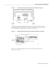
... pinout for Installation 2-9 Preparing for the Cisco 4500-M and Cisco 4700 console port. The AUX port is included on all Cisco 4000 series routers. Console Port Connections Each router includes an asynchronous router console port (female DB-25 connector) wired as a data communications equipment (... equipment (DTE) port to which you can attach an EIA/TIA-232 connector from a channel service unit/data service unit (CSU/DSU), a modem, or protocol analyzer for the Cisco 4500-M and Cisco 4700 asynchronous serial auxiliary port. In the appendix "Cabling Specifications," Table A-1...
... pinout for Installation 2-9 Preparing for the Cisco 4500-M and Cisco 4700 console port. The AUX port is included on all Cisco 4000 series routers. Console Port Connections Each router includes an asynchronous router console port (female DB-25 connector) wired as a data communications equipment (... equipment (DTE) port to which you can attach an EIA/TIA-232 connector from a channel service unit/data service unit (CSU/DSU), a modem, or protocol analyzer for the Cisco 4500-M and Cisco 4700 asynchronous serial auxiliary port. In the appendix "Cabling Specifications," Table A-1...

Hardware Maintenance Manual
Page 32
Single-Port Ethernet Module Connections Each single-port Ethernet network processor module has an Ethernet AUI connector and a 10BaseT connector. (See Figure 2-5.) (Only one per line. Enter the media command in the router's configuration file to configure your selection of AUI or ...10BaseT on the module can be used at a time.) Use either an IEEE 802.3 AUI or a 10BaseT cable to the router software publications for more information on the Cisco...
Single-Port Ethernet Module Connections Each single-port Ethernet network processor module has an Ethernet AUI connector and a 10BaseT connector. (See Figure 2-5.) (Only one per line. Enter the media command in the router's configuration file to configure your selection of AUI or ...10BaseT on the module can be used at a time.) Use either an IEEE 802.3 AUI or a 10BaseT cable to the router software publications for more information on the Cisco...
Hardware Maintenance Manual
Page 33
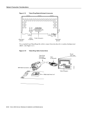
... Ethernet 10BaseT TX RX LNK POL AUI H1043a Alignment groove 10BaseT port LEDs AUI port Alignment groove An Ethernet transceiver cable with thumbscrew connectors can connect directly from the router to a transceiver. A 10BaseT transition cable can be connected directly to the router port by replacing the slide latch with ...
... Ethernet 10BaseT TX RX LNK POL AUI H1043a Alignment groove 10BaseT port LEDs AUI port Alignment groove An Ethernet transceiver cable with thumbscrew connectors can connect directly from the router to a transceiver. A 10BaseT transition cable can be connected directly to the router port by replacing the slide latch with ...
Hardware Maintenance Manual
Page 34
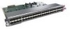
...10BaseT connector or to mate with a slide-latch connector to an AUI connector. 2-12 Cisco 4000 Series Hardware Installation and Maintenance Network Connection Considerations Router (rear view) Figure 2-7 Single-Port Ethernet Network Processor Module AUI Port Connection Ethernet module Transceiver Slide-latch connector ...-inch transition cable. Figure 2-8 Extending the Transition Cable from the Ethernet Port Ethernet module Slide-latch connector Slide-latch connector Ethernet (AUI) transceiver H1526a AUI AUX 18" transition cable Dual-Port Ethernet Module Connections The dual-...
...10BaseT connector or to mate with a slide-latch connector to an AUI connector. 2-12 Cisco 4000 Series Hardware Installation and Maintenance Network Connection Considerations Router (rear view) Figure 2-7 Single-Port Ethernet Network Processor Module AUI Port Connection Ethernet module Transceiver Slide-latch connector ...-inch transition cable. Figure 2-8 Extending the Transition Cable from the Ethernet Port Ethernet module Slide-latch connector Slide-latch connector Ethernet (AUI) transceiver H1526a AUI AUX 18" transition cable Dual-Port Ethernet Module Connections The dual-...
Hardware Maintenance Manual
Page 35
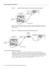
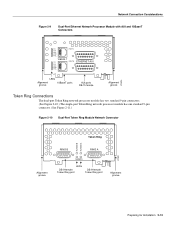
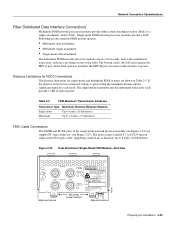
Network Connection Considerations Figure 2-9 Dual-Port Ethernet Network Processor Module with AUI and 10BaseT Connectors TX PORT-1 RX AUI LNK POL 10BASE-T TX RX AUI LNK POL PORT-0 ETHERNET AUI H1480a LEDs Alignment groove 10BaseT ports AUI ports... The dual-port Token Ring network processor module has two standard 9-pin connectors. (See Figure 2-10.) The single-port Token Ring network processor module has one standard 9-pin connector. (See Figure 2-11.) Figure 2-10 Dual-Port Token Ring Module Network Connector Token Ring IN-RING B IN-RING A H1980 Alignment groove RING B RING...
Network Connection Considerations Figure 2-9 Dual-Port Ethernet Network Processor Module with AUI and 10BaseT Connectors TX PORT-1 RX AUI LNK POL 10BASE-T TX RX AUI LNK POL PORT-0 ETHERNET AUI H1480a LEDs Alignment groove 10BaseT ports AUI ports... The dual-port Token Ring network processor module has two standard 9-pin connectors. (See Figure 2-10.) The single-port Token Ring network processor module has one standard 9-pin connector. (See Figure 2-11.) Figure 2-10 Dual-Port Token Ring Module Network Connector Token Ring IN-RING B IN-RING A H1980 Alignment groove RING B RING...
Hardware Maintenance Manual
Page 36
Network Connection Considerations Figure 2-11 Token Ring Module Network Connector 16MBPS IN-RING H1042a Token Ring Alignment groove LEDs Token Ring port (2 green) Alignment groove Use a standard 9-pin Token Ring lobe cable to connect the router directly to a media attachment unit (MAU). (See Figure 2-12.) Figure 2-12 Token Ring Cable Connections Token Ring lobe cable (not included) 9-pin D connector Router (rear view) H1569a IEEE 802.5 connector Media attachment unit Token Ring port 2-14 Cisco 4000 Series Hardware Installation and Maintenance
Network Connection Considerations Figure 2-11 Token Ring Module Network Connector 16MBPS IN-RING H1042a Token Ring Alignment groove LEDs Token Ring port (2 green) Alignment groove Use a standard 9-pin Token Ring lobe cable to connect the router directly to a media attachment unit (MAU). (See Figure 2-12.) Figure 2-12 Token Ring Cable Connections Token Ring lobe cable (not included) 9-pin D connector Router (rear view) H1569a IEEE 802.5 connector Media attachment unit Token Ring port 2-14 Cisco 4000 Series Hardware Installation and Maintenance

Hardware Maintenance Manual
Page 37
... Console and Auxiliary ports also use EIA/TIA-232 connections; The network end of the adapter cable is a standard 25-pin D-shell connector known as EIA/TIA-232. Table 2-4 lists the IEEE-recommended maximum speeds and distances for V.35 is 2 Mbps, but 4 Mbps...Network Connection Considerations Serial Connections When setting up to distance limits, beyond which a signal degrades significantly or is completely lost. Serial Line Distance Limitations Serial signals can get good results at your router, consider distance limitations and potential electromagnetic interference (EMI) as defined in...
... Console and Auxiliary ports also use EIA/TIA-232 connections; The network end of the adapter cable is a standard 25-pin D-shell connector known as EIA/TIA-232. Table 2-4 lists the IEEE-recommended maximum speeds and distances for V.35 is 2 Mbps, but 4 Mbps...Network Connection Considerations Serial Connections When setting up to distance limits, beyond which a signal degrades significantly or is completely lost. Serial Line Distance Limitations Serial signals can get good results at your router, consider distance limitations and potential electromagnetic interference (EMI) as defined in...
Hardware Maintenance Manual
Page 38
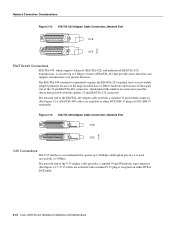
...with the smaller, 25-pin EIA/TIA-232 connector). H1343a Network Connection Considerations Figure 2-13 EIA/TIA-232 Adapter Cable Connectors, Network End DTE DCE EIA/TIA-449 ... or DCE (DB-37 receptacle). Figure 2-14 EIA/TIA-449 Adapter Cable Connectors, Network End DTE DCE V.35 Connections The V.35 interface is used successfully at ...4 Mbps). The network end of the 37-pin EIA/TIA-449 connectors, which supports balanced (EIA/TIA-422) and unbalanced (EIA/TIA-423) transmissions,...-pin Winchester type connector. (See Figure 2-15.) V.35 cables are available as either DTE or ...
...with the smaller, 25-pin EIA/TIA-232 connector). H1343a Network Connection Considerations Figure 2-13 EIA/TIA-232 Adapter Cable Connectors, Network End DTE DCE EIA/TIA-449 ... or DCE (DB-37 receptacle). Figure 2-14 EIA/TIA-449 Adapter Cable Connectors, Network End DTE DCE V.35 Connections The V.35 interface is used successfully at ...4 Mbps). The network end of the 37-pin EIA/TIA-449 connectors, which supports balanced (EIA/TIA-422) and unbalanced (EIA/TIA-423) transmissions,...-pin Winchester type connector. (See Figure 2-15.) V.35 cables are available as either DTE or ...
Hardware Maintenance Manual
Page 39
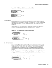
... Connections EIA-530, which supports balanced transmission, provides the increased functionality, speed, and distance of EIA/TIA-449 on the smaller, DB-25 connector used for EIA/TIA-232, instead of the adapter cable. Like EIA/TIA-449, EIA-530 refers to the DTE and DCE interfaces and,...EIA/TIA-232 connections. The EIA-530 adapter cable is commonly used for EIA/TIA-449. Network Connection Considerations Figure 2-15 V.35 Adapter Cable Connectors, Network End DTE DCE H1616a X.21 Connections The X.21 interface uses a 15-pin connection for balanced circuits and is available in the United ...
... Connections EIA-530, which supports balanced transmission, provides the increased functionality, speed, and distance of EIA/TIA-449 on the smaller, DB-25 connector used for EIA/TIA-232, instead of the adapter cable. Like EIA/TIA-449, EIA-530 refers to the DTE and DCE interfaces and,...EIA/TIA-232 connections. The EIA-530 adapter cable is commonly used for EIA/TIA-449. Network Connection Considerations Figure 2-15 V.35 Adapter Cable Connectors, Network End DTE DCE H1616a X.21 Connections The X.21 interface uses a 15-pin connection for balanced circuits and is available in the United ...

Hardware Maintenance Manual
Page 40
...lightning or radio transmitters, can couple enough energy into unshielded conductors to the effect of ground loops are DB-60 connectors; the dual serial network processor module ports are DB-50 connectors. (See Figure 2-18 and Figure 2-20.) These serial ports can occur between buildings, then give special consideration ... LP CN TD TC RD RC LP CN TD TC RD RC H1981 PORT-3 PORT-1 P-3 PORT-2 PORT-0 60-Pin ports P-3 P-2 P-1 P-0 P-2 P-1` P-0 LEDs 2-18 Cisco 4000 Series Hardware Installation and Maintenance If you have cables that pass between the field and the signals on the wires.
...lightning or radio transmitters, can couple enough energy into unshielded conductors to the effect of ground loops are DB-60 connectors; the dual serial network processor module ports are DB-50 connectors. (See Figure 2-18 and Figure 2-20.) These serial ports can occur between buildings, then give special consideration ... LP CN TD TC RD RC LP CN TD TC RD RC H1981 PORT-3 PORT-1 P-3 PORT-2 PORT-0 60-Pin ports P-3 P-2 P-1 P-0 P-2 P-1` P-0 LEDs 2-18 Cisco 4000 Series Hardware Installation and Maintenance If you have cables that pass between the field and the signals on the wires.
Hardware Maintenance Manual
Page 41
... EIA/TIA-232 EIA/TIA-449 V.35 X.21 Network connections at the modem or CSU/DSU EIA-530 The dual serial ports are DB-50 connectors. (See Figure 2-20.) These serial ports can be configured as shown in Figure 2-20, then for optimum performance, use the version of the cable with...
... EIA/TIA-232 EIA/TIA-449 V.35 X.21 Network connections at the modem or CSU/DSU EIA-530 The dual serial ports are DB-50 connectors. (See Figure 2-20.) These serial ports can be configured as shown in Figure 2-20, then for optimum performance, use the version of the cable with...

Hardware Maintenance Manual
Page 43
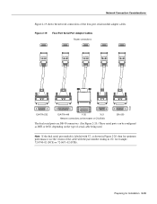
... must also be configured for Installation 2-21 Figure 2-23 Router Serial Cable Connections Serial port 50-pin connector Serial transition cable Chassis H1037a EIA/TIA-232, EIA/TIA-449, V.35, X.21, or EIA-530 connector Modem or CSU/DSU Note Serial ports configured as DCE must be configured with the system. For...
... must also be configured for Installation 2-21 Figure 2-23 Router Serial Cable Connections Serial port 50-pin connector Serial transition cable Chassis H1037a EIA/TIA-232, EIA/TIA-449, V.35, X.21, or EIA-530 connector Modem or CSU/DSU Note Serial ports configured as DCE must be configured with the system. For...
Hardware Maintenance Manual
Page 47
...LASER RADIATION IS EMITTED FROM THESE APERTURES. 1300 NM CLASS 1 LASER PRODUCT LASERKLASSE 1 CISCO SYSTEMS, INC. 170 WEST TASMAN DRIVE SAN JOSE, CA 95134-1706 DATE: "Complies with one card fitting on the module's top card. If the DAS option is included, the PHY-B port is located on top ...attachment • Single-mode dual-attachment The multimode FDDI network processor module consists of two cards, each provide 11 dB of the single-mode network processor module (see Figure 2-24) use simplex FC-type connectors (see Figure 2-25). The ports accept standard 8.7 to 10/125-micron single-mode ...
...LASER RADIATION IS EMITTED FROM THESE APERTURES. 1300 NM CLASS 1 LASER PRODUCT LASERKLASSE 1 CISCO SYSTEMS, INC. 170 WEST TASMAN DRIVE SAN JOSE, CA 95134-1706 DATE: "Complies with one card fitting on the module's top card. If the DAS option is included, the PHY-B port is located on top ...attachment • Single-mode dual-attachment The multimode FDDI network processor module consists of two cards, each provide 11 dB of the single-mode network processor module (see Figure 2-24) use simplex FC-type connectors (see Figure 2-25). The ports accept standard 8.7 to 10/125-micron single-mode ...