
Hardware Maintenance Manual
Page 5
... This Manual xv Document Objectives xv Audience xv Document Organization xv Document Conventions xvi Chapter 1 Cisco 4000 Series Overview 1-1 External Differences in Models of the Cisco 4000 Series 1-1 Series Specifications 1-2 Memory Systems 1-4 Chapter 2 Preparing for Installation 2-1 Safety ... Auxiliary Port Connections 2-9 Network Connection Considerations 2-10 Ethernet Connections 2-10 Token Ring Connections 2-13 Serial Connections 2-15 Fiber Distributed Data Interface Connections 2-25 BRI Connections 2-29 Channelized T1 Connections 2-30 Channelized E1 Connections 2-32 ATM Connections ...
... This Manual xv Document Objectives xv Audience xv Document Organization xv Document Conventions xvi Chapter 1 Cisco 4000 Series Overview 1-1 External Differences in Models of the Cisco 4000 Series 1-1 Series Specifications 1-2 Memory Systems 1-4 Chapter 2 Preparing for Installation 2-1 Safety ... Auxiliary Port Connections 2-9 Network Connection Considerations 2-10 Ethernet Connections 2-10 Token Ring Connections 2-13 Serial Connections 2-15 Fiber Distributed Data Interface Connections 2-25 BRI Connections 2-29 Channelized T1 Connections 2-30 Channelized E1 Connections 2-32 ATM Connections ...

Hardware Maintenance Manual
Page 20
... with the Channelized E1/ISDN PRI network interface module ((NP-CE1). For optimum heat dissipation, use the center slot position for the Cisco 4000 series follow: • Modular router platform • Flash memory capability • User-upgradable network processor modules, shared memory,... • Hardware thermal alarm to three network processor modules at a time, including Ethernet, Token Ring, serial, single-mode and multimode Fiber Distributed Data Interface (FDDI), ISDN BRI, G.703, channelized T1/PRI, channelized T1/PRI, and ATM modules. Series Specifications Figure 1-1 shows...
... with the Channelized E1/ISDN PRI network interface module ((NP-CE1). For optimum heat dissipation, use the center slot position for the Cisco 4000 series follow: • Modular router platform • Flash memory capability • User-upgradable network processor modules, shared memory,... • Hardware thermal alarm to three network processor modules at a time, including Ethernet, Token Ring, serial, single-mode and multimode Fiber Distributed Data Interface (FDDI), ISDN BRI, G.703, channelized T1/PRI, channelized T1/PRI, and ATM modules. Series Specifications Figure 1-1 shows...

Hardware Maintenance Manual
Page 28
... wrist strap • Screwdrivers, Number 1 and Number 2 Phillips • One serial port adapter cable for multimode Fiber Distributed Data Interface (FDDI) connections. 2-6 Cisco 4000 Series Hardware Installation and Maintenance Site Log Site Log The Site Log provides a historical record of your router. ...-449, or EIA-530 electrical interface. • Ethernet transceiver. • Token Ring media attachment unit (MAU). • Optical bypass switch or concentrator for each serial port to it into a T1 data stream with the remote device or network In addition, you need a...
... wrist strap • Screwdrivers, Number 1 and Number 2 Phillips • One serial port adapter cable for multimode Fiber Distributed Data Interface (FDDI) connections. 2-6 Cisco 4000 Series Hardware Installation and Maintenance Site Log Site Log The Site Log provides a historical record of your router. ...-449, or EIA-530 electrical interface. • Ethernet transceiver. • Token Ring media attachment unit (MAU). • Optical bypass switch or concentrator for each serial port to it into a T1 data stream with the remote device or network In addition, you need a...
Hardware Maintenance Manual
Page 47
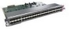
...EMITTED FROM THESE APERTURES. 1300 NM CLASS 1 LASER PRODUCT LASERKLASSE 1 CISCO SYSTEMS, INC. 170 WEST TASMAN DRIVE SAN JOSE, CA 95134-1706 DATE: "Complies with one card fitting on the module's top card. Table 2-5 FDDI Maximum Transmission Distances Transceiver Type Maximum Distance Between Stations...ports accept standard 8.7 to 10/125-micron single-mode fiber-optic cable, supporting connections at distances up to 1.2 miles (1.9 kilometers) FDDI Cable Connections The XMTR and RCVR ports of optical power. The bottom card is greater than the maximum distance shown, significant signal loss...
...EMITTED FROM THESE APERTURES. 1300 NM CLASS 1 LASER PRODUCT LASERKLASSE 1 CISCO SYSTEMS, INC. 170 WEST TASMAN DRIVE SAN JOSE, CA 95134-1706 DATE: "Complies with one card fitting on the module's top card. Table 2-5 FDDI Maximum Transmission Distances Transceiver Type Maximum Distance Between Stations...ports accept standard 8.7 to 10/125-micron single-mode fiber-optic cable, supporting connections at distances up to 1.2 miles (1.9 kilometers) FDDI Cable Connections The XMTR and RCVR ports of optical power. The bottom card is greater than the maximum distance shown, significant signal loss...
Hardware Maintenance Manual
Page 48
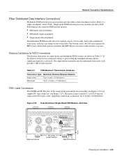
... ring and one to the ring. Keep the transmit port covered whenever a cable is not connected to FDDI standard 62.5/125 micron multimode fiber-optic cable. The media interface connector (MIC) connects to it. To connect to another dual-attachment station, connect PHY-A on the module... product meets the Class 1 Laser Emission Requirement from the aperture ports of the single-mode FDDI products when no fiber cable is the top port on the other DAS. 2-26 Cisco 4000 Series Hardware Installation and Maintenance H1349a Warning Invisible laser radiation may be emitted from CDRH FDDI.
... ring and one to the ring. Keep the transmit port covered whenever a cable is not connected to FDDI standard 62.5/125 micron multimode fiber-optic cable. The media interface connector (MIC) connects to it. To connect to another dual-attachment station, connect PHY-A on the module... product meets the Class 1 Laser Emission Requirement from the aperture ports of the single-mode FDDI products when no fiber cable is the top port on the other DAS. 2-26 Cisco 4000 Series Hardware Installation and Maintenance H1349a Warning Invisible laser radiation may be emitted from CDRH FDDI.
Hardware Maintenance Manual
Page 56
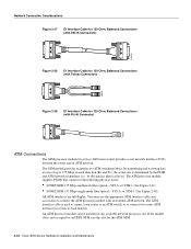
... Installation and Maintenance The ATM interface cable is not occupied by the specific physical layer). The ATM module provides an interface to ATM switching fabrics for a Cisco 4000 series router provides a user network interface (UNI) between the router and an ATM network. the actual rate is determined by ... ATM interface cable and accessories to the following physical layers: • SONET/SDH 155 Mbps multimode fiber optical-STS-3c or STM-1 (See Figure 2-41) • SONET/SDH 155 Mbps single-mode fiber optical-STS-3c or STM-1 (See Figure 2-40) All ATM interfaces are full-duplex. An ...
... Installation and Maintenance The ATM interface cable is not occupied by the specific physical layer). The ATM module provides an interface to ATM switching fabrics for a Cisco 4000 series router provides a user network interface (UNI) between the router and an ATM network. the actual rate is determined by ... ATM interface cable and accessories to the following physical layers: • SONET/SDH 155 Mbps multimode fiber optical-STS-3c or STM-1 (See Figure 2-41) • SONET/SDH 155 Mbps single-mode fiber optical-STS-3c or STM-1 (See Figure 2-40) All ATM interfaces are full-duplex. An ...
Hardware Maintenance Manual
Page 57
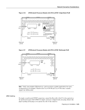
ATM Cabling For single- Therefore the Cisco 4500-M and Cisco 4700 routers currently support one ATM module. Preparing for Installation 2-35 Remove the plug by pulling on the module front panel. or multi-mode SONET connections, connect the fiber cable to be dropped. Network Connection Considerations...RX CELLS RX ALARM WARNING AVOID EXPOSUREÐINVISIBLE LASER RADIATION IS EMITTED FROM THESE APERTURES. 1300 NM CLASS 1 LASER PRODUCT LASERKLASSE 1 CISCO SYSTEMS, INC. 170 W. TASMAN DRIVE SAN JOSE CA. 95134 DATE: ÒComplies with FDA Radiation Performance Standards, 21 CFR, ...
ATM Cabling For single- Therefore the Cisco 4500-M and Cisco 4700 routers currently support one ATM module. Preparing for Installation 2-35 Remove the plug by pulling on the module front panel. or multi-mode SONET connections, connect the fiber cable to be dropped. Network Connection Considerations...RX CELLS RX ALARM WARNING AVOID EXPOSUREÐINVISIBLE LASER RADIATION IS EMITTED FROM THESE APERTURES. 1300 NM CLASS 1 LASER PRODUCT LASERKLASSE 1 CISCO SYSTEMS, INC. 170 W. TASMAN DRIVE SAN JOSE CA. 95134 DATE: ÒComplies with FDA Radiation Performance Standards, 21 CFR, ...

Hardware Maintenance Manual
Page 58
... to prevent accidental damage. When you received all PLIMs. Warning Invisible laser radiation can be shipped in the Warranty Package). 2-36 Cisco 4000 Series Hardware Installation and Maintenance Inspecting the System Before unpacking the system, make certain that you unpack each shipping container, check... the following items: • Router • 6-foot (1.8-meter) power cord • Bag of the single-mode ATM products when no fiber-optic cable is not ready, keep the chassis in appearance. This product meets the Class 1 Laser Emission Requirement from the aperture ports of...
... to prevent accidental damage. When you received all PLIMs. Warning Invisible laser radiation can be shipped in the Warranty Package). 2-36 Cisco 4000 Series Hardware Installation and Maintenance Inspecting the System Before unpacking the system, make certain that you unpack each shipping container, check... the following items: • Router • 6-foot (1.8-meter) power cord • Bag of the single-mode ATM products when no fiber-optic cable is not ready, keep the chassis in appearance. This product meets the Class 1 Laser Emission Requirement from the aperture ports of...
Hardware Maintenance Manual
Page 69
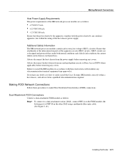
...advice from any analog telephone circuits or Basic Access ISDN (where applicable) before removing any doubt as to how to safely install the Cisco Systems BRI module correctly within the rating of the host chassis power supply. Dual-Attachment FDDI Connections Connect a dual-attachment FDDI module ... modules in accordance with the power drawn by the apparatus, together with these procedures to PHY-B on the other DAS using a multimode fiber-optic cable. (See Figure 3-10.) Installing the Router 3-11 If you have any covers. Making Network Connections Host Power Supply Requirements ...
...advice from any analog telephone circuits or Basic Access ISDN (where applicable) before removing any doubt as to how to safely install the Cisco Systems BRI module correctly within the rating of the host chassis power supply. Dual-Attachment FDDI Connections Connect a dual-attachment FDDI module ... modules in accordance with the power drawn by the apparatus, together with these procedures to PHY-B on the other DAS using a multimode fiber-optic cable. (See Figure 3-10.) Installing the Router 3-11 If you have any covers. Making Network Connections Host Power Supply Requirements ...
Hardware Maintenance Manual
Page 70
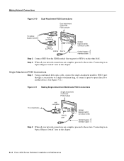
Single-Attachment FDDI Connections Step 1 Using a multimode fiber-optic cable, connect the single-attachment module's PHY-S port through a concentrator to a single-attachment ring, or connect it point-to-point directly to another device. (...-A (to PHY-B) PHY-B PHY-A RING OP FDDI OPT-BYPASS RING OP PHY-B (to PHY-A) PHY-B PHY-A Optical bypass switch connector (DIN) Optical bypass interface cable H1573a Step 2 Connect PHY-B on the FDDI module (the top port) to an Optical Bypass Switch" later in this chapter. 3-12 Cisco 4000 Series Hardware Installation and Maintenance
Single-Attachment FDDI Connections Step 1 Using a multimode fiber-optic cable, connect the single-attachment module's PHY-S port through a concentrator to a single-attachment ring, or connect it point-to-point directly to another device. (...-A (to PHY-B) PHY-B PHY-A RING OP FDDI OPT-BYPASS RING OP PHY-B (to PHY-A) PHY-B PHY-A Optical bypass switch connector (DIN) Optical bypass interface cable H1573a Step 2 Connect PHY-B on the FDDI module (the top port) to an Optical Bypass Switch" later in this chapter. 3-12 Cisco 4000 Series Hardware Installation and Maintenance
Hardware Maintenance Manual
Page 98
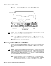
...rear mounting screws (not shown) if the module has them, and set the screws aside. 5-4 Cisco 4000 Series Hardware Installation and Maintenance Step 6 Set the component tray on your work surface or ... screws attached to the rear of the chassis with external rear mounting screws, which include the Fiber Distributed Data Interface (FDDI) module, these screws must first remove the network processor modules. Step...from underneath, either on your hands, to prevent it from falling. (See the hand in -line memory modules (SIMMs), you must be removed before the module can be safely lifted out of ...
...rear mounting screws (not shown) if the module has them, and set the screws aside. 5-4 Cisco 4000 Series Hardware Installation and Maintenance Step 6 Set the component tray on your work surface or ... screws attached to the rear of the chassis with external rear mounting screws, which include the Fiber Distributed Data Interface (FDDI) module, these screws must first remove the network processor modules. Step...from underneath, either on your hands, to prevent it from falling. (See the hand in -line memory modules (SIMMs), you must be removed before the module can be safely lifted out of ...

Hardware Maintenance Manual
Page 137
...b command (boot) C-2 Basic Rate Interface See BRI boot command D-3 boot ROMs, replacing 5-19 booting from Flash B-6 from the ROM monitor Cisco 4000-M C-2 Cisco 4500-M D-3 Cisco 4700 D-3 bootstrap clear memory contents C-2 stack trace, system software C-2 Break key (interrupt) C-1, D-1 BRI distance limitations 2-30, 3-6 making...35, four-port A-11 X.21, dual-port A-14 X.21, four-port A-15 serial, preparing to connect 2-21 single-mode fiber optic 2-25 specifications A-1 Token Ring lobe 2-14 transceiver 2-11 cables safety guidelines 2-3 ungrounded 2-3 uninsulated 2-3 caution, description xvii CE1 ...
...b command (boot) C-2 Basic Rate Interface See BRI boot command D-3 boot ROMs, replacing 5-19 booting from Flash B-6 from the ROM monitor Cisco 4000-M C-2 Cisco 4500-M D-3 Cisco 4700 D-3 bootstrap clear memory contents C-2 stack trace, system software C-2 Break key (interrupt) C-1, D-1 BRI distance limitations 2-30, 3-6 making...35, four-port A-11 X.21, dual-port A-14 X.21, four-port A-15 serial, preparing to connect 2-21 single-mode fiber optic 2-25 specifications A-1 Token Ring lobe 2-14 transceiver 2-11 cables safety guidelines 2-3 ungrounded 2-3 uninsulated 2-3 caution, description xvii CE1 ...

