Installation Guide
Page 1
...; Compliance and Safety Information, page 1 • Controller Overview, page 3 • Unpacking and Installing the Controller, page 8 • Using the Startup Wizard, page 24 • Controller Specifications, page 31 • Obtaining Documentation and Submitting a Service Request, page 31 • Cisco 90-Day Limited Hardware Warranty Terms, page 31 Compliance and Safety Information FCC Safety Compliance Statement Modifying...
...; Compliance and Safety Information, page 1 • Controller Overview, page 3 • Unpacking and Installing the Controller, page 8 • Using the Startup Wizard, page 24 • Controller Specifications, page 31 • Obtaining Documentation and Submitting a Service Request, page 31 • Cisco 90-Day Limited Hardware Warranty Terms, page 31 Compliance and Safety Information FCC Safety Compliance Statement Modifying...
Installation Guide
Page 2
... an equipment rack, be sure that accompanies this guide. Use the statement number provided at their own expense. Statement 1024 Statement 371-Power Cable and AC Adapter Cisco 5500 Series Wireless Controller Installation Guide 2 78-18998-01 Never defeat the ground conductor or operate the equipment in the absence of this guide are in a situation that suitable grounding is likely...
... an equipment rack, be sure that accompanies this guide. Use the statement number provided at their own expense. Statement 1024 Statement 371-Power Cable and AC Adapter Cisco 5500 Series Wireless Controller Installation Guide 2 78-18998-01 Never defeat the ground conductor or operate the equipment in the absence of this guide are in a situation that suitable grounding is likely...
Installation Guide
Page 4
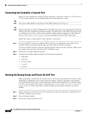
.... The console ports do not support hardware flow control. Cisco 5500 Series Wireless Controller Installation Guide 4 78-18998-01 You can be installed on any PC connected to the console port. See the "Connecting the Controller's Console Port" section on the cable and the adapter used at the end of a PC using a USB Type A to 5-pin mini Type B cable. EIA/TIA-232 Depending on...
.... The console ports do not support hardware flow control. Cisco 5500 Series Wireless Controller Installation Guide 4 78-18998-01 You can be installed on any PC connected to the console port. See the "Connecting the Controller's Console Port" section on the cable and the adapter used at the end of a PC using a USB Type A to 5-pin mini Type B cable. EIA/TIA-232 Depending on...

Installation Guide
Page 5
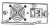
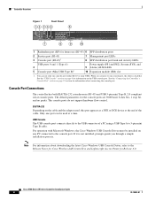
... B can be used. The LED indicators are not compatible. Only one console port can be active at a time. When a cable is not working properly, check the LEDs on /off switch 3 Power supply PS1 AC cable connection 5 4 Power supply PS2 slot with 5-pin mini Type B connectors. Note An amber LED could indicate an error or a possible hardware failure. 78-18998-01 Cisco 5500 Series Wireless Controller Installation Guide 5 Figure...
... B can be used. The LED indicators are not compatible. Only one console port can be active at a time. When a cable is not working properly, check the LEDs on /off switch 3 Power supply PS1 AC cable connection 5 4 Power supply PS2 slot with 5-pin mini Type B connectors. Note An amber LED could indicate an error or a possible hardware failure. 78-18998-01 Cisco 5500 Series Wireless Controller Installation Guide 5 Figure...
Installation Guide
Page 6
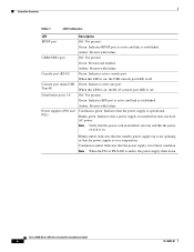
...power supply is installed but does not have AC power. Blinks amber: Indicates that the standby power supply fan is not spinning or that a power supply is over temperature. Cisco 5500 Series Wireless Controller Installation Guide 6 78-18998-01 Continuous amber: Indicates that the power switch is on , the RJ-45 console port LED is off . Amber: Present with failure...LED is in installed correctly and that the power supply is amber, the power supply shuts down. Green: Indicates RP/SP port is active and link is on . Note Verify that the power cord in failure condition. When...
...power supply is installed but does not have AC power. Blinks amber: Indicates that the standby power supply fan is not spinning or that a power supply is over temperature. Cisco 5500 Series Wireless Controller Installation Guide 6 78-18998-01 Continuous amber: Indicates that the power switch is on , the RJ-45 console port LED is off . Amber: Present with failure...LED is in installed correctly and that the power supply is amber, the power supply shuts down. Green: Indicates RP/SP port is active and link is on . Note Verify that the power cord in failure condition. When...
Installation Guide
Page 8
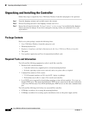
... item for downloading operating system software updates). Controller with factory-supplied power cord and mounting hardware - Cisco uses an integral TFTP server. If any item is damaged or missing, notify your authorized Cisco sales representative. This means that all packing materials to the shipping container and save it for securing captive installation screws on the power supply and fan Cisco 5500 Series Wireless Controller Installation Guide 8 78...
... item for downloading operating system software updates). Controller with factory-supplied power cord and mounting hardware - Cisco uses an integral TFTP server. If any item is damaged or missing, notify your authorized Cisco sales representative. This means that all packing materials to the shipping container and save it for securing captive installation screws on the power supply and fan Cisco 5500 Series Wireless Controller Installation Guide 8 78...
Installation Guide
Page 9
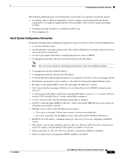
... administrative username and password. This is the default SSID that will supply IP addresses to clients. • The Control And Provisioning of lug • Wire-stripping tool Initial System Configuration Information Obtain the following additional items (not found in the accessory kit) are configuring a RADIUS server). • The country code for this installation. Yes is...
... administrative username and password. This is the default SSID that will supply IP addresses to clients. • The Control And Provisioning of lug • Wire-stripping tool Initial System Configuration Information Obtain the following additional items (not found in the accessory kit) are configuring a RADIUS server). • The country code for this installation. Yes is...
Installation Guide
Page 10
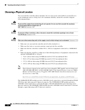
...) GBIC Module Installation Information and Specifications, at least: 4 in (10.16 cm) Statement 1076 Warning Take care when connecting units to the supply circuit so that wiring is within one of the following guidelines: Warning To prevent the system from overheating, do not operate it in a secure equipment room or wiring closet. Cisco 5500 Series Wireless Controller Installation Guide 10...
...) GBIC Module Installation Information and Specifications, at least: 4 in (10.16 cm) Statement 1076 Warning Take care when connecting units to the supply circuit so that wiring is within one of the following guidelines: Warning To prevent the system from overheating, do not operate it in a secure equipment room or wiring closet. Cisco 5500 Series Wireless Controller Installation Guide 10...
Installation Guide
Page 12
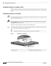
... chassis on each of the corners on the bottom of the front brackets to the controller using three M4 screws (see Figure 4). Statement 1028 Follow these steps to de-energize the unit...power supplies installed. Figure 4 Installing the Front Brackets RP SP USB0 USB1 CONSOLE EN EN Cisco 5500 Series Wireless Controller 12 34 56 78 Model 5508 PS1 PS2 SYS ACT 1 Front bracket 12 2 M4x0.7 x 8mm flat head screws 251200 Cisco 5500 Series Wireless Controller Installation Guide 12 78-18998-01 Installing the Controller in a 4-post equipment rack: Step 1 Attach one power supply connection...
... chassis on each of the corners on the bottom of the front brackets to the controller using three M4 screws (see Figure 4). Statement 1028 Follow these steps to de-energize the unit...power supplies installed. Figure 4 Installing the Front Brackets RP SP USB0 USB1 CONSOLE EN EN Cisco 5500 Series Wireless Controller 12 34 56 78 Model 5508 PS1 PS2 SYS ACT 1 Front bracket 12 2 M4x0.7 x 8mm flat head screws 251200 Cisco 5500 Series Wireless Controller Installation Guide 12 78-18998-01 Installing the Controller in a 4-post equipment rack: Step 1 Attach one power supply connection...

Installation Guide
Page 16
... 78 Model 5508 PS1 PS2 SYS ACT 251240 Installing the Controller in the rack. Statement 1028 Follow these steps to the opposite side. Two or more than one of the switch and the other devices installed in a 2-Post Rack-Flush Mount Caution The controller weighs 20 lbs (9.1 kg) with both power supplies installed. Cisco 5500 Series Wireless Controller Installation Guide...
... 78 Model 5508 PS1 PS2 SYS ACT 251240 Installing the Controller in the rack. Statement 1028 Follow these steps to the opposite side. Two or more than one of the switch and the other devices installed in a 2-Post Rack-Flush Mount Caution The controller weighs 20 lbs (9.1 kg) with both power supplies installed. Cisco 5500 Series Wireless Controller Installation Guide...

Installation Guide
Page 18
... power supplies installed. Statement 1028 Note When you use the mid-mount option, you cannot ground the chassis using your own grounding lug. You will need to de-energize the unit. Note Only three of the front brackets to the opposite side. Cisco 5500 Series Wireless Controller Installation Guide 18 78-18998-01 All connections must work together to install...
... power supplies installed. Statement 1028 Note When you use the mid-mount option, you cannot ground the chassis using your own grounding lug. You will need to de-energize the unit. Note Only three of the front brackets to the opposite side. Cisco 5500 Series Wireless Controller Installation Guide 18 78-18998-01 All connections must work together to install...

Installation Guide
Page 20
...controller. Figure 17 Location of the AC power cables used to provide power to the chassis must always be grounded. The receptacles of Chassis Ground on the left side of the chassis in the wire-down position. Cisco 5500 Series Wireless Controller Installation Guide 20 78-18998-01 Note To maintain the...the chassis in the wire-up position, or on the Controller (Right Side) 251241 RP SP USB0 USB1 CONSOLE EN EN Cisco 5500 Series Wireless Controller 12 34 56 78 Model 5508 PS1 PS2 SYS ACT Warning When installing or replacing the unit, the ground connection must be the grounding ...
...controller. Figure 17 Location of the AC power cables used to provide power to the chassis must always be grounded. The receptacles of Chassis Ground on the left side of the chassis in the wire-down position. Cisco 5500 Series Wireless Controller Installation Guide 20 78-18998-01 Note To maintain the...the chassis in the wire-up position, or on the Controller (Right Side) 251241 RP SP USB0 USB1 CONSOLE EN EN Cisco 5500 Series Wireless Controller 12 34 56 78 Model 5508 PS1 PS2 SYS ACT Warning When installing or replacing the unit, the ground connection must be the grounding ...

Installation Guide
Page 21
... 7 Use a wire-stripping tool to -metal contact, and insert the two M4 screws with copper conductors. Connect the strap to ensure adequate earth ground. The measurement should be NRTL listed and compatible with washers through the holes in the grounding lug. Figure 18 ESD Wrist Strap Connector Location RP SP USB0 USB1 CONSOLE EN EN Cisco 5500...
... 7 Use a wire-stripping tool to -metal contact, and insert the two M4 screws with copper conductors. Connect the strap to ensure adequate earth ground. The measurement should be NRTL listed and compatible with washers through the holes in the grounding lug. Figure 18 ESD Wrist Strap Connector Location RP SP USB0 USB1 CONSOLE EN EN Cisco 5500...
Installation Guide
Page 22
... conduct the power-on the power supply. Cisco 5500 Series Wireless Controller Installation Guide 22 78-18998-01 Note The first time that uses a VT-100 terminal emulator (such as described in the "Connecting the Controller's Console Port" section on your PC; Configure the terminal emulation program for more information about the USB console driver. Turn on self test (POST...
... conduct the power-on the power supply. Cisco 5500 Series Wireless Controller Installation Guide 22 78-18998-01 Note The first time that uses a VT-100 terminal emulator (such as described in the "Connecting the Controller's Console Port" section on your PC; Configure the terminal emulation program for more information about the USB console driver. Turn on self test (POST...
Installation Guide
Page 25
...transmit power assignment, for the group. 78-18998-01 Cisco 5500 Series Wireless Controller Installation Guide 25 Note The management interface is the default interface for the country in -band management of the mobility group/RF group to which you enter here is used to match the switch ... enter no to optimize RRM parameter settings, such as 1.1.1.1. Step 8 Enter the IP address of available country codes. Note Although the name that have different purposes. Step 11 Step 12 Step 13 Step 14 Enter the network name, or service set to support mobility management, DHCP relay, and...
...transmit power assignment, for the group. 78-18998-01 Cisco 5500 Series Wireless Controller Installation Guide 25 Note The management interface is the default interface for the country in -band management of the mobility group/RF group to which you enter here is used to match the switch ... enter no to optimize RRM parameter settings, such as 1.1.1.1. Step 8 Enter the IP address of available country codes. Note Although the name that have different purposes. Step 11 Step 12 Step 13 Step 14 Enter the network name, or service set to support mobility management, DHCP relay, and...
Installation Guide
Page 27
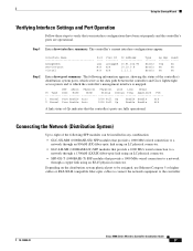
... Verifying Interface Settings and Port Operation Follow these steps to the controller. 78-18998-01 Cisco 5500 Series Wireless Controller Installation Guide 27 Step 1 Enter show port summary. The following information appears, showing the status of the following SFP modules can be assigned, use Ethernet Category 5 or higher cables or SX/LX/LH compatible fiber-optic cables to connect the...
... Verifying Interface Settings and Port Operation Follow these steps to the controller. 78-18998-01 Cisco 5500 Series Wireless Controller Installation Guide 27 Step 1 Enter show port summary. The following information appears, showing the status of the following SFP modules can be assigned, use Ethernet Category 5 or higher cables or SX/LX/LH compatible fiber-optic cables to connect the...
Installation Guide
Page 28
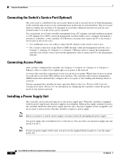
... to replace a power supply. you must first connect the PC to the switch's service port in slot 1 at the factory. Use of a network failure. As soon as the controller is equipped with two power supply units, the power supplies are hot swappable; Either power supply continues to associate. One power supply unit is optional. You have configured the controller, use a Category 5, Category 5e, Category 6, or Category 7 Ethernet cable to connect...
... to replace a power supply. you must first connect the PC to the switch's service port in slot 1 at the factory. Use of a network failure. As soon as the controller is equipped with two power supply units, the power supplies are hot swappable; Either power supply continues to associate. One power supply unit is optional. You have configured the controller, use a Category 5, Category 5e, Category 6, or Category 7 Ethernet cable to connect...

Installation Guide
Page 29
... hot swappable. Do not overtighten. Using the Startup Wizard Tools and Equipment Required To install a power supply unit, you need the following tools and equipment: • A power supply unit • A number 1 Phillips screwdriver Follow these steps to tighten the captive screw. Plug the power cord into the power supply unit and the other end into the slot until it in the card electrical connector...
... hot swappable. Do not overtighten. Using the Startup Wizard Tools and Equipment Required To install a power supply unit, you need the following tools and equipment: • A power supply unit • A number 1 Phillips screwdriver Follow these steps to tighten the captive screw. Plug the power cord into the power supply unit and the other end into the slot until it in the card electrical connector...
Installation Guide
Page 31
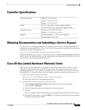
... your warranty and license agreements from the Information Packet appears. Cisco 90-Day Limited Hardware Warranty Terms There are a free service and Cisco currently supports RSS Version 2.0. Read the document online, or click the PDF icon to download and print the document in Adobe Portable Document Format (PDF). 78-18998-01 Cisco 5500 Series Wireless Controller Installation Guide 31 Click Go.
... your warranty and license agreements from the Information Packet appears. Cisco 90-Day Limited Hardware Warranty Terms There are a free service and Cisco currently supports RSS Version 2.0. Read the document online, or click the PDF icon to download and print the document in Adobe Portable Document Format (PDF). 78-18998-01 Cisco 5500 Series Wireless Controller Installation Guide 31 Click Go.
Installation Guide
Page 32
... b. Review the document online, or click the PDF icon to download and print the document in which you would like to ship a replacement part within ten (10) working days after receipt of Hardware Warranty Ninety (90) days. Actual delivery times can download the reader from Company telephone number Product model number Product serial number Maintenance contract number Cisco 5500 Series Wireless Controller Installation Guide 32...
... b. Review the document online, or click the PDF icon to download and print the document in which you would like to ship a replacement part within ten (10) working days after receipt of Hardware Warranty Ninety (90) days. Actual delivery times can download the reader from Company telephone number Product model number Product serial number Maintenance contract number Cisco 5500 Series Wireless Controller Installation Guide 32...


