
Hardware Installation Guide
Page 11
...10 Managing the Switch by Using the Cluster Management Suite C-1 Connecting to an Ethernet Port C-2 Launching the Switch Home Page C-3 CMS Requirements C-5 Recommended Configuration for Web-Based Management C-6 Operating System and Browser Support C-6 Supported Java Plug-Ins C-7 Java Plug-In Notes C-8 ...Need D-4 Stacking the Switches (Optional) D-5 Connecting to the Console Port D-7 Starting the Terminal Emulation Software D-9 Connecting to a Power Source D-9 Entering the Initial Configuration Information D-10 IP Settings D-10 Completing the Setup Program D-11 78-15136-02 Catalyst 3750 Switch...
...10 Managing the Switch by Using the Cluster Management Suite C-1 Connecting to an Ethernet Port C-2 Launching the Switch Home Page C-3 CMS Requirements C-5 Recommended Configuration for Web-Based Management C-6 Operating System and Browser Support C-6 Supported Java Plug-Ins C-7 Java Plug-In Notes C-8 ...Need D-4 Stacking the Switches (Optional) D-5 Connecting to the Console Port D-7 Starting the Terminal Emulation Software D-9 Connecting to a Power Source D-9 Entering the Initial Configuration Information D-10 IP Settings D-10 Completing the Setup Program D-11 78-15136-02 Catalyst 3750 Switch...

Hardware Installation Guide
Page 32
... receive a DHCP address from the switch. For information about troubleshooting a POST failure, see Chapter 4, "Troubleshooting," to determine a course of the power cable to a grounded AC outlet. You cannot start Express Setup when there are green. Caution Do not start Express Setup until POST has completed.... the other end of action. When POST is also green on a single switch or on a stack master switch. The IP address is also required if you can connect to configure a switch. The SYST LED turns amber if the POST fails. POST lasts approximately 1 minute. You do not...
... receive a DHCP address from the switch. For information about troubleshooting a POST failure, see Chapter 4, "Troubleshooting," to determine a course of the power cable to a grounded AC outlet. You cannot start Express Setup when there are green. Caution Do not start Express Setup until POST has completed.... the other end of action. When POST is also green on a single switch or on a stack master switch. The IP address is also required if you can connect to configure a switch. The SYST LED turns amber if the POST fails. POST lasts approximately 1 minute. You do not...

Hardware Installation Guide
Page 49
...Table 2-1 lists the LED colors and their meanings. System is receiving power but is providing power to another device (redundancy has been allocated to a neighboring device). Press the Standby/Active button on . Contact Cisco Systems. The internal power supply in a fault condition. RPS is not functioning properly. RPS ... RPS Status RPS is operating normally. RPS is connected but is connected and ready to provide back-up power, if required. For information on the System LED colors during power-on self-test (POST), see the "Connecting to the 10/100 and 10/100/1000 Ports" section...
...Table 2-1 lists the LED colors and their meanings. System is receiving power but is providing power to another device (redundancy has been allocated to a neighboring device). Press the Standby/Active button on . Contact Cisco Systems. The internal power supply in a fault condition. RPS is not functioning properly. RPS ... RPS Status RPS is operating normally. RPS is connected but is connected and ready to provide back-up power, if required. For information on the System LED colors during power-on self-test (POST), see the "Connecting to the 10/100 and 10/100/1000 Ports" section...

Hardware Installation Guide
Page 68
...you don't specify the length of the mounting brackets - To connect the switch console port to a terminal, you should power the switch and verify that adapter from Cisco. For console port and adapter pinout information, see the "Cable and Adapter Specifications" section on the switch and observe ... 3750-24TS, 3750G-24T, and 3750-48TS switches) - StackWise cable: 0.5-meter, 1-meter, or 3-meter cable. These sections describe the steps required to connect a PC to the switch console port, and to -DB-9 adapter cable. You can order a kit (part number ACS-DSBUASYN=) containing...
...you don't specify the length of the mounting brackets - To connect the switch console port to a terminal, you should power the switch and verify that adapter from Cisco. For console port and adapter pinout information, see the "Cable and Adapter Specifications" section on the switch and observe ... 3750-24TS, 3750G-24T, and 3750-48TS switches) - StackWise cable: 0.5-meter, 1-meter, or 3-meter cable. These sections describe the steps required to connect a PC to the switch console port, and to -DB-9 adapter cable. You can order a kit (part number ACS-DSBUASYN=) containing...

Hardware Installation Guide
Page 72
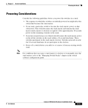
If you plan to stack your Cisco supplier. The "Recommended Cabling Configurations" section on page 2-...not have , you can order it easier to cable the switches. • Length of cable. If you require the 1-meter cable or 3-meter cable, you might need different sized cables. The Catalyst 3750-24TS, 3750G-... the rear panel, make it from your switches, read these sections: • Planning Considerations, page 3-12 • Powering Considerations, page 3-13 • Cabling Considerations, page 3-14 • Recommended Cabling Configurations, page 3-15 Planning Considerations Before...
If you plan to stack your Cisco supplier. The "Recommended Cabling Configurations" section on page 2-...not have , you can order it easier to cable the switches. • Length of cable. If you require the 1-meter cable or 3-meter cable, you might need different sized cables. The Catalyst 3750-24TS, 3750G-... the rear panel, make it from your switches, read these sections: • Planning Considerations, page 3-12 • Powering Considerations, page 3-13 • Cabling Considerations, page 3-14 • Recommended Cabling Configurations, page 3-15 Planning Considerations Before...
Hardware Installation Guide
Page 73
... might affect the switch that becomes the stack master. • If you want a particular switch to become the stack master, power on that can cause a stack master re-election or to manually elect the stack master, refer to or remove it to the "Managing Switch Stacks... Guide 3-13 Note For conditions that switch first. This switch becomes the stack master and remains the stack master until a master re-election is required. Chapter 3 Switch Installation Planning the Stack Powering Considerations Consider the following guidelines before you add it from an existing switch stack.
... might affect the switch that becomes the stack master. • If you want a particular switch to become the stack master, power on that can cause a stack master re-election or to manually elect the stack master, refer to or remove it to the "Managing Switch Stacks... Guide 3-13 Note For conditions that switch first. This switch becomes the stack master and remains the stack master until a master re-election is required. Chapter 3 Switch Installation Planning the Stack Powering Considerations Consider the following guidelines before you add it from an existing switch stack.

Hardware Installation Guide
Page 119
... the Catalyst 3750G-12S Switch Environmental Ranges Operating temperature Storage temperature Relative humidity Operating altitude Storage altitude Power Requirements AC input voltage DC input voltages for RPS 300 DC input voltages for RPS 675 Power consumption Power rating 32 to 113°F (0 to 45°C) -13 to 158°F (-25 to 70°C) 10...
... the Catalyst 3750G-12S Switch Environmental Ranges Operating temperature Storage temperature Relative humidity Operating altitude Storage altitude Power Requirements AC input voltage DC input voltages for RPS 300 DC input voltages for RPS 675 Power consumption Power rating 32 to 113°F (0 to 45°C) -13 to 158°F (-25 to 70°C) 10...

Hardware Installation Guide
Page 120
... the Catalyst 3750-24TS Switch Environmental Ranges Operating temperature Storage temperature Relative humidity Operating altitude Storage altitude Power Requirements AC input voltage DC input voltages for RPS 300 DC input voltages for RPS 675 Power consumption Power rating 32 to 113°F (0 to 45°C) -13 to 158°F (-25 to 70°C) 10...
... the Catalyst 3750-24TS Switch Environmental Ranges Operating temperature Storage temperature Relative humidity Operating altitude Storage altitude Power Requirements AC input voltage DC input voltages for RPS 300 DC input voltages for RPS 675 Power consumption Power rating 32 to 113°F (0 to 45°C) -13 to 158°F (-25 to 70°C) 10...

Hardware Installation Guide
Page 121
... to 70°C) Relative humidity 10 to 85% (noncondensing) Operating altitude Up to 10,000 ft (3049 m) Storage altitude Up to 15,000 ft (4573 m) Power Requirements AC input voltage 100 to 240 VAC (autoranging) 1.6A/0.9A, 50 to 60 Hz DC input voltage for RPS 300 +12V @13A DC input voltages... for RPS 675 +12V @13A Power consumption 165W, 563 BTUs per hour Power rating 0.165 kVA Physical Dimensions Weight 10 lb (4.55 kg) Dimensions (H x D x W) 1.73 x 12.83 x 17.5 in. (4.39 x 32.59 x 44.45 cm...
... to 70°C) Relative humidity 10 to 85% (noncondensing) Operating altitude Up to 10,000 ft (3049 m) Storage altitude Up to 15,000 ft (4573 m) Power Requirements AC input voltage 100 to 240 VAC (autoranging) 1.6A/0.9A, 50 to 60 Hz DC input voltage for RPS 300 +12V @13A DC input voltages... for RPS 675 +12V @13A Power consumption 165W, 563 BTUs per hour Power rating 0.165 kVA Physical Dimensions Weight 10 lb (4.55 kg) Dimensions (H x D x W) 1.73 x 12.83 x 17.5 in. (4.39 x 32.59 x 44.45 cm...

Hardware Installation Guide
Page 122
... Relative humidity 10 to 85% (noncondensing) Operating altitude Up to 10,000 ft (3049 m) Storage altitude Up to 15,000 ft (4573 m) Power Requirements AC input voltage 100 to 240 VAC (autoranging) 2.3A/1.5A, 50 to 60 Hz DC input voltages for RPS 675 +12V @17A... 29.46 x 44.45 cm) Table A-5 Specifications for the Catalyst 3750-48TS Switch Environmental Ranges Operating temperature Storage temperature Relative humidity Operating altitude Storage altitude Power Requirements AC input voltage 32 to 113°F (0 to 45°C) -13 to 158°F (-25 to 70°C) 10 to 85% (noncondensing) ...
... Relative humidity 10 to 85% (noncondensing) Operating altitude Up to 10,000 ft (3049 m) Storage altitude Up to 15,000 ft (4573 m) Power Requirements AC input voltage 100 to 240 VAC (autoranging) 2.3A/1.5A, 50 to 60 Hz DC input voltages for RPS 675 +12V @17A... 29.46 x 44.45 cm) Table A-5 Specifications for the Catalyst 3750-48TS Switch Environmental Ranges Operating temperature Storage temperature Relative humidity Operating altitude Storage altitude Power Requirements AC input voltage 32 to 113°F (0 to 45°C) -13 to 158°F (-25 to 70°C) 10 to 85% (noncondensing) ...
Hardware Installation Guide
Page 154
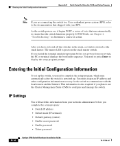
...the PC or terminal displays the bootloader sequence. You need this information from your RPS. After you have powered all the switches in the stack, a switch is also required if you plan to use the Cluster Management Suite (CMS) to configure and manage the switch. This ...Entering the Initial Configuration Information Appendix D Quick Setup By Using the CLI-Based Setup Program Note If you are connecting the switch to a Cisco redundant power system (RPS), refer to the documentation that the switch functions properly. If POST fails, see Chapter 4, "Troubleshooting," to determine a course ...
...the PC or terminal displays the bootloader sequence. You need this information from your RPS. After you have powered all the switches in the stack, a switch is also required if you plan to use the Cluster Management Suite (CMS) to configure and manage the switch. This ...Entering the Initial Configuration Information Appendix D Quick Setup By Using the CLI-Based Setup Program Note If you are connecting the switch to a Cisco redundant power system (RPS), refer to the documentation that the switch functions properly. If POST fails, see Chapter 4, "Troubleshooting," to determine a course ...
Hardware Installation Guide
Page 192
... Phones, connecting to 3-45 Cisco RPS See RPS CiscoView 2-18 CLI 2-18 accessing by using Express Setup D-2 accessing through console port D-3 Cluster Management Suite See CMS CMS 2-18 accessing your switch C-1 operating systems and supported browsers C-6 requirements C-5 to C-7 supported Java plug-ins C-7...to 3-48 connectivity problems, solving 4-3 connectors and cables 10/100/1000 ports B-1 to B-2 10/100 ports B-3 to B-4 console port B-6 to B-11 power (AC and RPS) 2-16 SC connectors B-5 SFP module ports B-5 See also cables console port connecting to 3-8, D-7 connectors and cables B-6 to B-11 ...
... Phones, connecting to 3-45 Cisco RPS See RPS CiscoView 2-18 CLI 2-18 accessing by using Express Setup D-2 accessing through console port D-3 Cluster Management Suite See CMS CMS 2-18 accessing your switch C-1 operating systems and supported browsers C-6 requirements C-5 to C-7 supported Java plug-ins C-7...to 3-48 connectivity problems, solving 4-3 connectors and cables 10/100/1000 ports B-1 to B-2 10/100 ports B-3 to B-4 console port B-6 to B-11 power (AC and RPS) 2-16 SC connectors B-5 SFP module ports B-5 See also cables console port connecting to 3-8, D-7 connectors and cables B-6 to B-11 ...
Hardware Installation Guide
Page 193
...connecting to 1000BASE-T SFP module ports 3-49 connectivity problems 4-5 pinout four twisted-pair, 1000BASE-T ports B-8 four twisted-pair 10/100 ports B-7 D DC power RPS 2-2 to 2-3 diagnosing problems 4-3 dimensions A-2 to A-5 document conventions xvi duplex LED 2-11 E electrical noise, avoiding 3-7 electromagnetic interference (EMI) ...18 humidity, relative A-1 to A-4 I installation assigning the IP Address D-10 connecting to an Ethernet port C-2 connecting to a power source D-9 rack-mounting 3-18 to 3-36 site requirements 3-6 78-15136-02 Catalyst 3750 Switch Hardware Installation Guide IN-3
...connecting to 1000BASE-T SFP module ports 3-49 connectivity problems 4-5 pinout four twisted-pair, 1000BASE-T ports B-8 four twisted-pair 10/100 ports B-7 D DC power RPS 2-2 to 2-3 diagnosing problems 4-3 dimensions A-2 to A-5 document conventions xvi duplex LED 2-11 E electrical noise, avoiding 3-7 electromagnetic interference (EMI) ...18 humidity, relative A-1 to A-4 I installation assigning the IP Address D-10 connecting to an Ethernet port C-2 connecting to a power source D-9 rack-mounting 3-18 to 3-36 site requirements 3-6 78-15136-02 Catalyst 3750 Switch Hardware Installation Guide IN-3


