
Hardware Installation Guide
Page 8
...or Connecting Devices to the Switch 1-12 Product Overview 2-1 Features 2-1 Front Panel Description 2-3 10/100 and 10/100/1000 Ports 2-6 SFP Module Slots 2-7 SFP Modules 2-7 LEDs 2-8 System LED 2-9 RPS LED 2-9 Master LED 2-10 Port LEDs and Modes 2-10 Rear Panel Description 2-14 StackWise ...Ports 2-15 Power Connectors 2-16 Internal Power Supply Connector 2-16 Cisco RPS Connector 2-16 Console Port 2-17 Management Options 2-18 Network Configurations 2-19 ...
...or Connecting Devices to the Switch 1-12 Product Overview 2-1 Features 2-1 Front Panel Description 2-3 10/100 and 10/100/1000 Ports 2-6 SFP Module Slots 2-7 SFP Modules 2-7 LEDs 2-8 System LED 2-9 RPS LED 2-9 Master LED 2-10 Port LEDs and Modes 2-10 Rear Panel Description 2-14 StackWise ...Ports 2-15 Power Connectors 2-16 Internal Power Supply Connector 2-16 Cisco RPS Connector 2-16 Console Port 2-17 Management Options 2-18 Network Configurations 2-19 ...

Hardware Installation Guide
Page 10
...Slots 3-43 Connecting to the 10/100 and 10/100/1000 Ports 3-44 Connecting to an SFP Module 3-46 Connecting to a Fiber-Optic SFP Module 3-47 Connecting to 1000BASE-T SFP Modules 3-48 Where to Go Next 3-50 4 C H A P T E R ...Specifications A-1 B A P P E N D I X Connector and Cable Specifications B-1 Connector Specifications B-1 10/100/1000 Ports B-1 Connecting to 1000BASE-T Devices B-2 10/100 Ports B-3 SFP Module Ports B-5 Console Port B-6 Cable and Adapter Specifications B-6 Two Twisted-Pair Cable Pinouts B-6 Four Twisted-Pair Cable Pinouts for 10/100 Ports B-7 Four Twisted-Pair...
...Slots 3-43 Connecting to the 10/100 and 10/100/1000 Ports 3-44 Connecting to an SFP Module 3-46 Connecting to a Fiber-Optic SFP Module 3-47 Connecting to 1000BASE-T SFP Modules 3-48 Where to Go Next 3-50 4 C H A P T E R ...Specifications A-1 B A P P E N D I X Connector and Cable Specifications B-1 Connector Specifications B-1 10/100/1000 Ports B-1 Connecting to 1000BASE-T Devices B-2 10/100 Ports B-3 SFP Module Ports B-5 Console Port B-6 Cable and Adapter Specifications B-6 Two Twisted-Pair Cable Pinouts B-6 Four Twisted-Pair Cable Pinouts for 10/100 Ports B-7 Four Twisted-Pair...

Hardware Installation Guide
Page 33
...-15136-02 Catalyst 3750 Switch Hardware Installation Guide 1-5 Note If all of the LEDs begin to a 10/100 Ethernet port or small form-factor pluggable (SFP) module port on page 4-2. Chapter 1 Using Express Setup Starting Express Setup Follow these steps to start the Express Setup program: Step 1 Step 2 Verify that the...
...-15136-02 Catalyst 3750 Switch Hardware Installation Guide 1-5 Note If all of the LEDs begin to a 10/100 Ethernet port or small form-factor pluggable (SFP) module port on page 4-2. Chapter 1 Using Express Setup Starting Express Setup Follow these steps to start the Express Setup program: Step 1 Step 2 Verify that the...

Hardware Installation Guide
Page 42
... Features Chapter 2 Product Overview Figure 2-1 through Figure 2-5 show the Catalyst 3750 switches. Catalyst 3750-48TS-48 10/100 Ethernet ports and 4 SFP module slots - For 10/100/1000 ports, autonegotiates the speed and supports only full-duplex mode • The Catalyst 3750 switches support stacking. ...Connection for optional Cisco RPS 300 redundant power system that operates on AC input and supplies backup DC power output to nine switches in half-duplex mode ...
... Features Chapter 2 Product Overview Figure 2-1 through Figure 2-5 show the Catalyst 3750 switches. Catalyst 3750-48TS-48 10/100 Ethernet ports and 4 SFP module slots - For 10/100/1000 ports, autonegotiates the speed and supports only full-duplex mode • The Catalyst 3750 switches support stacking. ...Connection for optional Cisco RPS 300 redundant power system that operates on AC input and supplies backup DC power output to nine switches in half-duplex mode ...

Hardware Installation Guide
Page 43
...The first member of the pair (port 1) is above port 4, and so on . In Figure 2-3 the SFP port are numbered 1 through 24. Chapter 2 Product Overview Front Panel Description Note The Cisco RPS 300 does not support the Catalyst 3750G-24TS switch. - Port 3 is above the second member (port ...2) on the Catalyst 3750G-24T and 3750G-24TS are numbered 1 (left , as shown in pairs. The ports are grouped in Figure 2-1. The SFP port numbers are grouped in Figure 2-2 and Figure 2-3. The first member of Catalyst 3750 switches. Figure 2-1 Catalyst 3750-24TS Front Panel 86541 SYST ...
...The first member of the pair (port 1) is above port 4, and so on . In Figure 2-3 the SFP port are numbered 1 through 24. Chapter 2 Product Overview Front Panel Description Note The Cisco RPS 300 does not support the Catalyst 3750G-24TS switch. - Port 3 is above the second member (port ...2) on the Catalyst 3750G-24T and 3750G-24TS are numbered 1 (left , as shown in pairs. The ports are grouped in Figure 2-1. The SFP port numbers are grouped in Figure 2-2 and Figure 2-3. The first member of Catalyst 3750 switches. Figure 2-1 Catalyst 3750-24TS Front Panel 86541 SYST ...

Hardware Installation Guide
Page 44
... 14 13X 15 16 17 18 19 20 21 22 23 24 23X 14X 24X Catalyst 3750 SERIES 25 26 27 28 1 2 1 10/100 ports 2 SFP module ports The Catalyst 3750G-12S SFP module slots are grouped in three sets of four, as shown in Figure 2-4.
... 14 13X 15 16 17 18 19 20 21 22 23 24 23X 14X 24X Catalyst 3750 SERIES 25 26 27 28 1 2 1 10/100 ports 2 SFP module ports The Catalyst 3750G-12S SFP module slots are grouped in three sets of four, as shown in Figure 2-4.

Hardware Installation Guide
Page 45
The SFP port numbers are 1 (top) and 2 (bottom) and so on . The first member of the pair (port 1) is...Front Panel Description 97166 SYST RPS MASTR STAT DUPLX SPEED STACK MODE 1 2 3 4 5 6 7 8 9 10 Catalyst 3750 SERIES 11 12 1 1 SFP module ports The Catalyst 3750-48TS 10/100 ports are grouped in Figure 2-1. Port 3 is above port 4, and so on . Figure 2-5 Catalyst 3750-48TS... 44 45 46 47 48 47X 32X 34X 48X Catalyst 3750 SERIES 1 3 2 4 1 2 1 10/100 ports 2 SFP module ports 78-15136-02 Catalyst 3750 Switch Hardware Installation Guide 2-5 The ports are numbered 1 through 48.
The SFP port numbers are 1 (top) and 2 (bottom) and so on . The first member of the pair (port 1) is...Front Panel Description 97166 SYST RPS MASTR STAT DUPLX SPEED STACK MODE 1 2 3 4 5 6 7 8 9 10 Catalyst 3750 SERIES 11 12 1 1 SFP module ports The Catalyst 3750-48TS 10/100 ports are grouped in Figure 2-1. Port 3 is above port 4, and so on . Figure 2-5 Catalyst 3750-48TS... 44 45 46 47 48 47X 32X 34X 48X Catalyst 3750 SERIES 1 3 2 4 1 2 1 10/100 ports 2 SFP module ports 78-15136-02 Catalyst 3750 Switch Hardware Installation Guide 2-5 The ports are numbered 1 through 48.

Hardware Installation Guide
Page 47
... when inserted in the Catalyst 3750 release notes. The Catalyst 3750 models support these Cisco SFP options: • 1000BASE-LX • 1000BASE-SX • 1000BASE-T For more information about these SFP modules, refer to a copper SFP module. Chapter 2 Product Overview Front Panel Description SFP Module Slots The SFP module slots support the SFP modules listed in an...
... when inserted in the Catalyst 3750 release notes. The Catalyst 3750 models support these Cisco SFP options: • 1000BASE-LX • 1000BASE-SX • 1000BASE-T For more information about these SFP modules, refer to a copper SFP module. Chapter 2 Product Overview Front Panel Description SFP Module Slots The SFP module slots support the SFP modules listed in an...

Hardware Installation Guide
Page 50
..., all the other switches in different port modes. Table 2-4 lists the mode LEDs and their meanings. Port LEDs and Modes Each RJ-45 port and SFP module slot has a port LED. Table 2-5 explains how to display SPEED, all the switches in the stack change a mode, press the Mode button ... master to interpret the port LED colors in the stack also display SPEED. 2-10 Catalyst 3750 Switch Hardware Installation Guide 78-15136-02 Note The Cisco RPS 300 does not support the Catalyst 3750G-24TS switches. Table 2-2 lists the LED colors and their associated port mode and meaning. If your...
..., all the other switches in different port modes. Table 2-4 lists the mode LEDs and their meanings. Port LEDs and Modes Each RJ-45 port and SFP module slot has a port LED. Table 2-5 explains how to display SPEED, all the switches in the stack change a mode, press the Mode button ... master to interpret the port LED colors in the stack also display SPEED. 2-10 Catalyst 3750 Switch Hardware Installation Guide 78-15136-02 Note The Cisco RPS 300 does not support the Catalyst 3750G-24TS switches. Table 2-2 lists the LED colors and their associated port mode and meaning. If your...

Hardware Installation Guide
Page 52
... mode or in half-duplex mode at 10 Mbps. Note When installed in Catalyst 3750 switches, 1000BASE-T SFP modules can be members of a stack. Green Member number of other switches in the stack. The port... LEDs 3 and 4 are no more members in the stack. SFP ports Off Port is operating at 10 or 100 Mbps. The first nine port LEDs show the status for ...rear panel) are up, and the representative stack LEDs are amber when the ports are down: • SFP port LEDs 1 and 2 on the Catalyst 3750-24TS switch show the position of member switches in a...
... mode or in half-duplex mode at 10 Mbps. Note When installed in Catalyst 3750 switches, 1000BASE-T SFP modules can be members of a stack. Green Member number of other switches in the stack. The port... LEDs 3 and 4 are no more members in the stack. SFP ports Off Port is operating at 10 or 100 Mbps. The first nine port LEDs show the status for ...rear panel) are up, and the representative stack LEDs are amber when the ports are down: • SFP port LEDs 1 and 2 on the Catalyst 3750-24TS switch show the position of member switches in a...

Hardware Installation Guide
Page 53
... not green, the stack is operating at full bandwidth. Chapter 2 Product Overview Front Panel Description • SFP port LEDs 3 and 4 on the Catalyst 3750-48TS switch show the status for StackWise ports 1 and 2, respectively. • SFP port LEDs 27 and 28 on the Catalyst 3750G-24TS switch show the status for StackWise.... • The 10/100/1000 port LEDs 23 and 24 on the Catalyst 3750G-24T switch show the status for StackWise ports 1 and 2, respectively. • SFP port LEDs 11 and 12 on all the switches in the stack, the stack is not operating at full bandwidth (32 Gbps).
... not green, the stack is operating at full bandwidth. Chapter 2 Product Overview Front Panel Description • SFP port LEDs 3 and 4 on the Catalyst 3750-48TS switch show the status for StackWise ports 1 and 2, respectively. • SFP port LEDs 27 and 28 on the Catalyst 3750G-24TS switch show the status for StackWise.... • The 10/100/1000 port LEDs 23 and 24 on the Catalyst 3750G-24T switch show the status for StackWise ports 1 and 2, respectively. • SFP port LEDs 11 and 12 on all the switches in the stack, the stack is not operating at full bandwidth (32 Gbps).

Hardware Installation Guide
Page 61
...; Connecting StackWise Cable to StackWise Ports, page 3-37 • Connecting to the 10/100 and 10/100/1000 Ports, page 3-44 • Connecting to an SFP Module, page 3-46 • Where to keep in this order: • Preparing for Installation This section covers these topics: • Warnings, page 3-2 • EMC Regulatory...
...; Connecting StackWise Cable to StackWise Ports, page 3-37 • Connecting to the 10/100 and 10/100/1000 Ports, page 3-44 • Connecting to an SFP Module, page 3-46 • Where to keep in this order: • Preparing for Installation This section covers these topics: • Warnings, page 3-2 • EMC Regulatory...

Hardware Installation Guide
Page 66
...ports is sufficient for reliable communications. The mode-conditioning patch cord is required for 1000BASE-SX and 1000BASE-LX fiber-optic SFP connections. Preparing for Installation Chapter 3 Switch Installation Installation Guidelines When determining where to place the switch, be easily read. ...mode-conditioning patch cord is required. Catalyst 3750 Switch Hardware Installation Guide 3-6 78-15136-02 Table 3-1 Fiber-Optic SFP Module Port Cabling Specifications SFP Module Wavelength (nanometers) Fiber Type Core Size (micron) Modal Bandwidth (MHz/km) Cable Distance 1000BASE-SX 850 ...
...ports is sufficient for reliable communications. The mode-conditioning patch cord is required for 1000BASE-SX and 1000BASE-LX fiber-optic SFP connections. Preparing for Installation Chapter 3 Switch Installation Installation Guidelines When determining where to place the switch, be easily read. ...mode-conditioning patch cord is required. Catalyst 3750 Switch Hardware Installation Guide 3-6 78-15136-02 Table 3-1 Fiber-Optic SFP Module Port Cabling Specifications SFP Module Wavelength (nanometers) Fiber Type Core Size (micron) Modal Bandwidth (MHz/km) Cable Distance 1000BASE-SX 850 ...

Hardware Installation Guide
Page 90
...; Run the setup program. See the "Connecting to the 10/100 and 10/100/1000 Ports" section on page 3-44 and the "Connecting to an SFP Module" section on page 1-13. To use the CLI, enter commands at the Switch> prompt through the console port by using a terminal program or through...
...; Run the setup program. See the "Connecting to the 10/100 and 10/100/1000 Ports" section on page 3-44 and the "Connecting to an SFP Module" section on page 1-13. To use the CLI, enter commands at the Switch> prompt through the console port by using a terminal program or through...

Hardware Installation Guide
Page 96
... an AC power source. See the "Connecting to the 10/100 and 10/100/1000 Ports" section on page 3-44 and the "Connecting to an SFP Module" section on page 3-46 to a Power Source" section on page C-3. See the "Connecting to the 10/100 and 10/100/1000 Ports" section on... page 3-44 and the "Connecting to an SFP Module" section on page 3-46 to the recessed areas on the switch. Attach the four rubber feet to complete the installation. See the "Connecting to...
... an AC power source. See the "Connecting to the 10/100 and 10/100/1000 Ports" section on page 3-44 and the "Connecting to an SFP Module" section on page 3-46 to a Power Source" section on page C-3. See the "Connecting to the 10/100 and 10/100/1000 Ports" section on... page 3-44 and the "Connecting to an SFP Module" section on page 3-46 to the recessed areas on the switch. Attach the four rubber feet to complete the installation. See the "Connecting to...

Hardware Installation Guide
Page 100
... has an internal serial EEPROM that the Catalyst 3750 switch supports. You can use any combination of SFP modules. Use only Cisco SFP modules on the other end of the cable, and the cable must match the wave-length specifications on the Catalyst 3750 switch. ... must not exceed the stipulated cable length for SFP connections. This encoding provides a way for Cisco to identify and validate that the SFP module meets the requirements for the list of SFP modules that is encoded with security information. SFP modules are inserted into SFP module slots on page 3-6 for cable stipulations for...
... has an internal serial EEPROM that the Catalyst 3750 switch supports. You can use any combination of SFP modules. Use only Cisco SFP modules on the other end of the cable, and the cable must match the wave-length specifications on the Catalyst 3750 switch. ... must not exceed the stipulated cable length for SFP connections. This encoding provides a way for Cisco to identify and validate that the SFP module meets the requirements for the list of SFP modules that is encoded with security information. SFP modules are inserted into SFP module slots on page 3-6 for cable stipulations for...

Hardware Installation Guide
Page 101
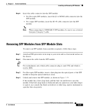
...the cable connector, or the optical interfaces in the SFP module. Removing and installing an SFP module can shorten its useful life. Do not remove and insert SFP modules more often than is absolutely necessary. Installing SFP Modules into the SFP module slot, follow these steps: Step 1 Step...do not install or remove fiber-optic SFP modules with a Bale-Clasp Latch 86575 To insert an SFP module into SFP Module Slots Figure 3-37 shows an SFP module that has a bale-clasp latch. Chapter 3 Switch Installation Installing and Removing SFP Modules For detailed instructions on installing, ...
...the cable connector, or the optical interfaces in the SFP module. Removing and installing an SFP module can shorten its useful life. Do not remove and insert SFP modules more often than is absolutely necessary. Installing SFP Modules into the SFP module slot, follow these steps: Step 1 Step...do not install or remove fiber-optic SFP modules with a Bale-Clasp Latch 86575 To insert an SFP module into SFP Module Slots Figure 3-37 shows an SFP module that has a bale-clasp latch. Chapter 3 Switch Installation Installing and Removing SFP Modules For detailed instructions on installing, ...

Hardware Installation Guide
Page 102
...fiber-optic cable until you are ready to connect the cable. Caution Do not remove the dust plugs from the fiber-optic SFP module port or the rubber caps from contamination and ambient light. 3-42 Catalyst 3750 Switch Hardware Installation Guide 78-15136-02 Installing and... Removing SFP Modules Chapter 3 Switch Installation Note On some SFP modules, the send and receive (TX and RX) markings might be replaced by arrows that show the direction of...
...fiber-optic cable until you are ready to connect the cable. Caution Do not remove the dust plugs from the fiber-optic SFP module port or the rubber caps from contamination and ambient light. 3-42 Catalyst 3750 Switch Hardware Installation Guide 78-15136-02 Installing and... Removing SFP Modules Chapter 3 Switch Installation Note On some SFP modules, the send and receive (TX and RX) markings might be replaced by arrows that show the direction of...
Hardware Installation Guide
Page 103
... (RX). Chapter 3 Switch Installation Installing and Removing SFP Modules Step 6 Insert the cable connector into the SFP module: • For fiber-optic SFP modules, insert the LC or MT-RJ cable connector into the SFP module. • For copper SFP modules, insert the RJ-45 cable connector into the... the bale-clasp latch. 78-15136-02 Catalyst 3750 Switch Hardware Installation Guide 3-43 Unlock and remove the SFP module, as shown in Figure 3-39. Note When connecting to 1000BASE-T SFP modules, be sure to use a small, flat-blade screwdriver or other long, narrow instrument to open it...
... (RX). Chapter 3 Switch Installation Installing and Removing SFP Modules Step 6 Insert the cable connector into the SFP module: • For fiber-optic SFP modules, insert the LC or MT-RJ cable connector into the SFP module. • For copper SFP modules, insert the RJ-45 cable connector into the... the bale-clasp latch. 78-15136-02 Catalyst 3750 Switch Hardware Installation Guide 3-43 Unlock and remove the SFP module, as shown in Figure 3-39. Note When connecting to 1000BASE-T SFP modules, be sure to use a small, flat-blade screwdriver or other long, narrow instrument to open it...
Hardware Installation Guide
Page 104
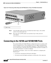
...ports autonegotiate both speed and duplex. • Set the port speed and duplex parameters on both ends of attached devices. Place the removed SFP module in no linkage. Connecting to operate at the speed of the connection. 3-44 Catalyst 3750 Switch Hardware Installation Guide 78-15136-02 Connecting... 16 17 18 19 20 21 22 23 24 23X 14X 24X Catalyst 3750 SERIES 1 2 1 1 Bale clasp Step 5 Step 6 Grasp the SFP module between your thumb and index finger, and carefully remove it from the module slot. Connecting devices that do not support autonegotiation, you can explicitly...
...ports autonegotiate both speed and duplex. • Set the port speed and duplex parameters on both ends of attached devices. Place the removed SFP module in no linkage. Connecting to operate at the speed of the connection. 3-44 Catalyst 3750 Switch Hardware Installation Guide 78-15136-02 Connecting... 16 17 18 19 20 21 22 23 24 23X 14X 24X Catalyst 3750 SERIES 1 2 1 1 Bale clasp Step 5 Step 6 Grasp the SFP module between your thumb and index finger, and carefully remove it from the module slot. Connecting devices that do not support autonegotiation, you can explicitly...

