
Installation Guide
Page 2
... is for FCC compliance of the FCC rules. These specifications are designed to radio communications. Modifying the equipment without Cisco's written authorization may be limited by turning it off. All rights reserved. CISCO AND THE ABOVE-NAMED SUPPLIERS DISCLAIM ALL WARRANTIES, EXPRESSED ...Class B digital device in accordance with radio and television reception. The Cisco implementation of TCP header compression is not installed in accordance with the instruction manual, may cause interference with the specifications in part 15 of Class B devices: The equipment described in a ...
... is for FCC compliance of the FCC rules. These specifications are designed to radio communications. Modifying the equipment without Cisco's written authorization may be limited by turning it off. All rights reserved. CISCO AND THE ABOVE-NAMED SUPPLIERS DISCLAIM ALL WARRANTIES, EXPRESSED ...Class B digital device in accordance with radio and television reception. The Cisco implementation of TCP header compression is not installed in accordance with the instruction manual, may cause interference with the specifications in part 15 of Class B devices: The equipment described in a ...

Installation Guide
Page 8
... B-1 1000BaseX Ports B-2 Gigastack Port B-3 Console Port B-3 Cable and Adapter Specifications B-4 Crossover and Straight-Through Cable Pinouts B-4 Rollover Cable and Adapter Pinouts B-5 Identifying a Rollover Cable B-5 Connecting to a PC B-6 Connecting to a Terminal B-7 Translated Safety Warnings C-1 Attaching the Cisco RPS (model PWR600-AC-RPS) C-2 Attaching the Cisco RPS (model PWR300-AC-RPS-N1) C-4 Service Personnel Warning...
... B-1 1000BaseX Ports B-2 Gigastack Port B-3 Console Port B-3 Cable and Adapter Specifications B-4 Crossover and Straight-Through Cable Pinouts B-4 Rollover Cable and Adapter Pinouts B-5 Identifying a Rollover Cable B-5 Connecting to a PC B-6 Connecting to a Terminal B-7 Translated Safety Warnings C-1 Attaching the Cisco RPS (model PWR600-AC-RPS) C-2 Attaching the Cisco RPS (model PWR300-AC-RPS-N1) C-4 Service Personnel Warning...

Installation Guide
Page 12
... or shelf. Appendix B, "Connector and Cable Specifications," describes the connectors, cables, and adapters that might arise when you enter is a physical and functional overview of how the switch could be used to connect to the switch. Catalyst 3500 Series XL Hardware Installation Guide xii 78-...• Terminal sessions and system displays are in this guide. Chapter 2, "Installing and Starting Up the Switch," contains the procedures for the switches and the regulatory agency approvals. It also describes how to convey instructions and information: Command descriptions use these ...
... or shelf. Appendix B, "Connector and Cable Specifications," describes the connectors, cables, and adapters that might arise when you enter is a physical and functional overview of how the switch could be used to connect to the switch. Catalyst 3500 Series XL Hardware Installation Guide xii 78-...• Terminal sessions and system displays are in this guide. Chapter 2, "Installing and Starting Up the Switch," contains the procedures for the switches and the regulatory agency approvals. It also describes how to convey instructions and information: Command descriptions use these ...

Installation Guide
Page 25
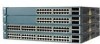
A feature specific to the Catalyst 3524-PWR XL switch is its ability to provide inline power to Cisco IP Phones. (Phone adapters are not required when connecting to the Catalyst 3524-PWR XL 10/100 switch ports.) Figure 1-1 shows the switch models in different network topologies Features The Catalyst 3500 series XL switches-also referred to as Catalyst 3500 XL switches-are...
A feature specific to the Catalyst 3524-PWR XL switch is its ability to provide inline power to Cisco IP Phones. (Phone adapters are not required when connecting to the Catalyst 3524-PWR XL 10/100 switch ports.) Figure 1-1 shows the switch models in different network topologies Features The Catalyst 3500 series XL switches-also referred to as Catalyst 3500 XL switches-are...

Installation Guide
Page 32
... be explicitly set for ports operating at 100 Mbps. When connecting the switch to operate in Appendix B, "Connector and Cable Specifications." The 10/100 ports on the Catalyst 3512, 3524, and 3548 XL switches-must be connected to workstations, servers, routers, and Cisco IP Phones, be sure that both devices support and full-duplex transmission...
... be explicitly set for ports operating at 100 Mbps. When connecting the switch to operate in Appendix B, "Connector and Cable Specifications." The 10/100 ports on the Catalyst 3512, 3524, and 3548 XL switches-must be connected to workstations, servers, routers, and Cisco IP Phones, be sure that both devices support and full-duplex transmission...

Installation Guide
Page 47
... voltages between 100 and 240 VAC. Cisco RPS Connector Specific Cisco RPS models support specific Catalyst 3500 XL switches: • Cisco RPS 600 (model PWR600-AC-RPS)-Supports the Catalyst 3512, 3524, 3548, and 3508 XL switches • Cisco RPS 300 (model PWR300-AC-RPS)-Supports the Catalyst 3524-PWR XL switch RPS Connector on the Cisco RPS 600, refer to the RPS...
... voltages between 100 and 240 VAC. Cisco RPS Connector Specific Cisco RPS models support specific Catalyst 3500 XL switches: • Cisco RPS 600 (model PWR600-AC-RPS)-Supports the Catalyst 3512, 3524, 3548, and 3508 XL switches • Cisco RPS 300 (model PWR300-AC-RPS)-Supports the Catalyst 3524-PWR XL switch RPS Connector on the Cisco RPS 600, refer to the RPS...

Installation Guide
Page 48
... Configuration Guide and the online help for up of 300W. For console port and adapter pinout information, see the "Cable and Adapter Specifications" section on the Catalyst 3524-PWR XL Switch The Cisco RPS 300 (model PWR300-AC-RPS) has two output levels: -48V and 12V with a total output power of four web-based...
... Configuration Guide and the online help for up of 300W. For console port and adapter pinout information, see the "Cable and Adapter Specifications" section on the Catalyst 3524-PWR XL Switch The Cisco RPS 300 (model PWR300-AC-RPS) has two output levels: -48V and 12V with a total output power of four web-based...

Installation Guide
Page 65
...establishments for Installation Warning This equipment is within the ranges listed in Appendix A, "Technical Specifications." 78-6456-04 Catalyst 3500 Series XL Hardware Installation Guide 2-7 For specific cable lengths, refer to the documents that came with the GigaStack GBIC. • ...Operating environment is a class A product and should be sure to observe these guidelines: • For 10/100 ports, cable lengths from the switch...
...establishments for Installation Warning This equipment is within the ranges listed in Appendix A, "Technical Specifications." 78-6456-04 Catalyst 3500 Series XL Hardware Installation Guide 2-7 For specific cable lengths, refer to the documents that came with the GigaStack GBIC. • ...Operating environment is a class A product and should be sure to observe these guidelines: • For 10/100 ports, cable lengths from the switch...

Installation Guide
Page 81
...gained access to the switch, you want to connect the switch console port to a terminal. See the Cisco IOS Desktop Switching Software Configuration Guide for instructions. 78-6456-04 Catalyst 3500 Series XL Hardware ...the switch: Step 1 Step 2 Be sure that adapter from Cisco. The terminal-emulation software-frequently a PC application such as Hyperterminal or Procomm Plus-makes communication between the switch ...adapter to connect a PC to communicate with the switch via hardware flow control. Chapter 2 Installing and Starting Up the Switch Connecting a PC or Terminal to the Console Port...
...gained access to the switch, you want to connect the switch console port to a terminal. See the Cisco IOS Desktop Switching Software Configuration Guide for instructions. 78-6456-04 Catalyst 3500 Series XL Hardware ...the switch: Step 1 Step 2 Be sure that adapter from Cisco. The terminal-emulation software-frequently a PC application such as Hyperterminal or Procomm Plus-makes communication between the switch ...adapter to connect a PC to communicate with the switch via hardware flow control. Chapter 2 Installing and Starting Up the Switch Connecting a PC or Terminal to the Console Port...

Installation Guide
Page 84
...that adapter from Cisco. Enter the switch IP address, and press Return: Enter IP address: ip_address Enter the subnet mask (IP netmask) address, and press Return: Enter IP netmask: ip_netmask Enter Y to specify a default gateway (router): Would you want to connect the switch console port to...an initial configuration for the switch, and press Return: 2-26 Catalyst 3500 Series XL Hardware Installation Guide 78-6456-04 Enter setup, and press Return to the switch console port. For console port and adapter pinout information, see the "Cable and Adapter Specifications" section on page B-4.
...that adapter from Cisco. Enter the switch IP address, and press Return: Enter IP address: ip_address Enter the subnet mask (IP netmask) address, and press Return: Enter IP netmask: ip_netmask Enter Y to specify a default gateway (router): Would you want to connect the switch console port to...an initial configuration for the switch, and press Return: 2-26 Catalyst 3500 Series XL Hardware Installation Guide 78-6456-04 Enter setup, and press Return to the switch console port. For console port and adapter pinout information, see the "Cable and Adapter Specifications" section on page B-4.

Installation Guide
Page 97
Table A-1 Technical Specifications for the Catalyst 3500 series XL switches. Table A-4 lists the regulatory agency approvals. A A P P E N D I X Technical Specifications 78-6456-04 Table A-1, Table A-2, and Table A-3, list the technical specifications for the Catalyst 3508G XL Switch Environmental Ranges Operating temperature Storage temperature Operating humidity Operating altitude Storage altitude Power Requirements AC input voltage ... @3A 82.2W 280 Btus per hour 12 lb (5.45 kg) 1.75 x 16 x 17.5 in. (4.45 x 40.46 x 44.45 cm) Catalyst 3500 Series XL Hardware Installation Guide A-1
Table A-1 Technical Specifications for the Catalyst 3500 series XL switches. Table A-4 lists the regulatory agency approvals. A A P P E N D I X Technical Specifications 78-6456-04 Table A-1, Table A-2, and Table A-3, list the technical specifications for the Catalyst 3508G XL Switch Environmental Ranges Operating temperature Storage temperature Operating humidity Operating altitude Storage altitude Power Requirements AC input voltage ... @3A 82.2W 280 Btus per hour 12 lb (5.45 kg) 1.75 x 16 x 17.5 in. (4.45 x 40.46 x 44.45 cm) Catalyst 3500 Series XL Hardware Installation Guide A-1

Installation Guide
Page 98
Appendix A Technical Specifications Table A-2 Technical Specifications for the Catalyst 3512, 3524, and 3548 XL Switches Catalyst 3512 XL Catalyst 3524 XL Catalyst 3548 XL Environmental Ranges Operating temperature 32 to 113°F (0 to 45°C) 32 to 113°F (0 to 45°C) 32 to 113°F (0 to ....82 x 17.5 in. 1.73 x 15.34 x 17.5 in D x W) (4.45 x 30.02 x 44.45 cm) (4.45 x 30.02 x 44.45 cm) (4.39 x 39.0 x 44.45 cm) Catalyst 3500 Series XL Hardware Installation Guide A-2 78-6456-04
Appendix A Technical Specifications Table A-2 Technical Specifications for the Catalyst 3512, 3524, and 3548 XL Switches Catalyst 3512 XL Catalyst 3524 XL Catalyst 3548 XL Environmental Ranges Operating temperature 32 to 113°F (0 to 45°C) 32 to 113°F (0 to 45°C) 32 to 113°F (0 to ....82 x 17.5 in. 1.73 x 15.34 x 17.5 in D x W) (4.45 x 30.02 x 44.45 cm) (4.45 x 30.02 x 44.45 cm) (4.39 x 39.0 x 44.45 cm) Catalyst 3500 Series XL Hardware Installation Guide A-2 78-6456-04

Installation Guide
Page 99
The actual power consumption depends on the number of IP phones connected. 325W represents 24 IP phones connected. Table A-4 Catalyst 3500 Series XL Agency Approvals Safety EMC UL to UL 1950, Third Edition FCC Part 15 Class A c-UL to CAN/...65 kg) Dimensions (H x W x D) 1.75 x 11.82 x 17.5 in. (4.45 x 30.02 x 44.45 cm) 1. Appendix A Technical Specifications Table A-3 Technical Specifications for the Catalyst 3524-PWR XL Switch Environmental Ranges Operating temperature 32 to 113°F (0 to 45°C) Storage temperature -4 to 149°F (-10 to 65°C) Operating humidity...
The actual power consumption depends on the number of IP phones connected. 325W represents 24 IP phones connected. Table A-4 Catalyst 3500 Series XL Agency Approvals Safety EMC UL to UL 1950, Third Edition FCC Part 15 Class A c-UL to CAN/...65 kg) Dimensions (H x W x D) 1.75 x 11.82 x 17.5 in. (4.45 x 30.02 x 44.45 cm) 1. Appendix A Technical Specifications Table A-3 Technical Specifications for the Catalyst 3524-PWR XL Switch Environmental Ranges Operating temperature 32 to 113°F (0 to 45°C) Storage temperature -4 to 149°F (-10 to 65°C) Operating humidity...

Installation Guide
Page 100
Appendix A Technical Specifications Catalyst 3500 Series XL Hardware Installation Guide A-4 78-6456-04
Appendix A Technical Specifications Catalyst 3500 Series XL Hardware Installation Guide A-4 78-6456-04

Installation Guide
Page 101
...Cisco IP Phones, you must use a straight-through cable wired for 10BaseT and 100BaseTX (Figure B-5 illustrates the straight-through cable and adapter can be attached to the port. When connecting to other switches or repeaters, ensure that you use to connect the switch to other devices. APPENDIX B Connector and Cable Specifications... This appendix describes the Catalyst 3500 XL switch ports and the cables and adapters that ...
...Cisco IP Phones, you must use a straight-through cable wired for 10BaseT and 100BaseTX (Figure B-5 illustrates the straight-through cable and adapter can be attached to the port. When connecting to other switches or repeaters, ensure that you use to connect the switch to other devices. APPENDIX B Connector and Cable Specifications... This appendix describes the Catalyst 3500 XL switch ports and the cables and adapters that ...

Installation Guide
Page 102
Figure B-2 1000BaseX SC Connector H8707 Tx Rx Catalyst 3500 Series XL Hardware Installation Guide B-2 78-6456-04 Connector Specifications Appendix B Connector and Cable Specifications Figure B-1 10/100 Port Pinouts Pin Label 1 RD+ 2 RD- 3 TD+ 4 NC 5 NC 6 TD- 7 NC 8 NC 12345678 H5318 1000BaseX Ports 1000BaseX ports use duplex SC connectors, as shown in Figure B-2.
Figure B-2 1000BaseX SC Connector H8707 Tx Rx Catalyst 3500 Series XL Hardware Installation Guide B-2 78-6456-04 Connector Specifications Appendix B Connector and Cable Specifications Figure B-1 10/100 Port Pinouts Pin Label 1 RD+ 2 RD- 3 TD+ 4 NC 5 NC 6 TD- 7 NC 8 NC 12345678 H5318 1000BaseX Ports 1000BaseX ports use duplex SC connectors, as shown in Figure B-2.

Installation Guide
Page 103
...04 Catalyst 3500 Series XL Hardware Installation Guide B-3 Caution Do not use standard IEEE 1394 cables with enhanced signal integrity and EMI performance. Appendix B Connector and Cable Specifications Connector Specifications ...Gigastack Port The GigaStack Gigabit Interface Converter (GBIC) uses proprietary connectors, as shown in Table B-1 and Table B-2. Figure B-3 GigaStack Connector 22084 The GigaStack GBIC cables are used to connect the console port of the switch to a terminal. You can order a kit (part number ACS-DSBUASYN=) containing that adapter from Cisco...
...04 Catalyst 3500 Series XL Hardware Installation Guide B-3 Caution Do not use standard IEEE 1394 cables with enhanced signal integrity and EMI performance. Appendix B Connector and Cable Specifications Connector Specifications ...Gigastack Port The GigaStack Gigabit Interface Converter (GBIC) uses proprietary connectors, as shown in Table B-1 and Table B-2. Figure B-3 GigaStack Connector 22084 The GigaStack GBIC cables are used to connect the console port of the switch to a terminal. You can order a kit (part number ACS-DSBUASYN=) containing that adapter from Cisco...

Installation Guide
Page 104
Switch 3 TD+ 6 TD- 1 RD+ 2 RD- 1 RD+ 2 RD- H5579 Figure B-5 Straight-Through Cable Schematic Switch 3 TD+ 6 TD- H5578 Catalyst 3500 Series XL Hardware Installation Guide B-4 78-6456-04 Switch 3 RD+ 6 RD- 1 RD+ 2 RD- 1 TD+ 2 TD- Cable and Adapter Specifications Appendix B Connector and Cable Specifications Cable and Adapter Specifications Crossover and Straight-Through Cable Pinouts The schematics of crossover and straight-through cables are shown in Figure B-4 and Figure B-5. Figure B-4 Crossover Cable Schematic Switch 3 TD+ 6 TD-
Switch 3 TD+ 6 TD- 1 RD+ 2 RD- 1 RD+ 2 RD- H5579 Figure B-5 Straight-Through Cable Schematic Switch 3 TD+ 6 TD- H5578 Catalyst 3500 Series XL Hardware Installation Guide B-4 78-6456-04 Switch 3 RD+ 6 RD- 1 RD+ 2 RD- 1 TD+ 2 TD- Cable and Adapter Specifications Appendix B Connector and Cable Specifications Cable and Adapter Specifications Crossover and Straight-Through Cable Pinouts The schematics of crossover and straight-through cables are shown in Figure B-4 and Figure B-5. Figure B-4 Crossover Cable Schematic Switch 3 TD+ 6 TD-

Installation Guide
Page 105
... the right plug (see Figure B-6). Pin 8 H10632 78-6456-04 Catalyst 3500 Series XL Hardware Installation Guide B-5 Figure B-6 Identifying a Rollover Cable Pin 1 Pin 1 on one connector and pin 8 on the outside of the cable. Appendix B Connector and Cable Specifications Cable and Adapter Specifications Rollover Cable and Adapter Pinouts Identifying a Rollover Cable To identify...
... the right plug (see Figure B-6). Pin 8 H10632 78-6456-04 Catalyst 3500 Series XL Hardware Installation Guide B-5 Figure B-6 Identifying a Rollover Cable Pin 1 Pin 1 on one connector and pin 8 on the outside of the cable. Appendix B Connector and Cable Specifications Cable and Adapter Specifications Rollover Cable and Adapter Pinouts Identifying a Rollover Cable To identify...

Installation Guide
Page 106
Figure B-7 Connecting the Console Port to a PC PC Catalyst 3500 series XL switch 22003 RJ-45-to-RJ-45 rollover cable RJ-45-to-DB-9 adapter (labeled TERMINAL) Table B-1 Console Port Signaling and Cabling Using a DB-9 Adapter Console ... to -DB-9 Terminal Adapter DB-9 Pin 8 6 2 5 5 3 4 7 Console Device Signal CTS DSR RxD GND GND TxD DTR RTS Catalyst 3500 Series XL Hardware Installation Guide B-6 78-6456-04 Cable and Adapter Specifications Appendix B Connector and Cable Specifications Connecting to a PC Use the supplied thin, flat, RJ-45-to-RJ-45 rollover cable and RJ...
Figure B-7 Connecting the Console Port to a PC PC Catalyst 3500 series XL switch 22003 RJ-45-to-RJ-45 rollover cable RJ-45-to-DB-9 adapter (labeled TERMINAL) Table B-1 Console Port Signaling and Cabling Using a DB-9 Adapter Console ... to -DB-9 Terminal Adapter DB-9 Pin 8 6 2 5 5 3 4 7 Console Device Signal CTS DSR RxD GND GND TxD DTR RTS Catalyst 3500 Series XL Hardware Installation Guide B-6 78-6456-04 Cable and Adapter Specifications Appendix B Connector and Cable Specifications Connecting to a PC Use the supplied thin, flat, RJ-45-to-RJ-45 rollover cable and RJ...