
Installation Guide
Page 2
... equipment to this product not authorized by different circuit breakers or fuses.) Modifications to one of the FCC rules. These specifications are designed to part 15 of its peripheral devices. If the equipment causes interference to radio or television reception, try to...UNABLE TO LOCATE THE SOFTWARE LICENSE OR LIMITED WARRANTY, CONTACT YOUR CISCO REPRESENTATIVE FOR A COPY. In that interference will be required to correct any interference to radio communications. Operation of California. THE SPECIFICATIONS AND INFORMATION REGARDING THE PRODUCTS IN THIS MANUAL ARE SUBJECT TO...
... equipment to this product not authorized by different circuit breakers or fuses.) Modifications to one of the FCC rules. These specifications are designed to part 15 of its peripheral devices. If the equipment causes interference to radio or television reception, try to...UNABLE TO LOCATE THE SOFTWARE LICENSE OR LIMITED WARRANTY, CONTACT YOUR CISCO REPRESENTATIVE FOR A COPY. In that interference will be required to correct any interference to radio communications. Operation of California. THE SPECIFICATIONS AND INFORMATION REGARDING THE PRODUCTS IN THIS MANUAL ARE SUBJECT TO...

Installation Guide
Page 8
... B-1 1000BaseX Ports B-2 Gigastack Port B-3 Console Port B-3 Cable and Adapter Specifications B-4 Crossover and Straight-Through Cable Pinouts B-4 Rollover Cable and Adapter Pinouts B-5 Identifying a Rollover Cable B-5 Connecting to a PC B-6 Connecting to a Terminal B-7 Translated Safety Warnings C-1 Attaching the Cisco RPS (model PWR600-AC-RPS) C-2 Attaching the Cisco RPS (model PWR300-AC-RPS-N1) C-4 Service Personnel Warning...
... B-1 1000BaseX Ports B-2 Gigastack Port B-3 Console Port B-3 Cable and Adapter Specifications B-4 Crossover and Straight-Through Cable Pinouts B-4 Rollover Cable and Adapter Pinouts B-5 Identifying a Rollover Cable B-5 Connecting to a PC B-6 Connecting to a Terminal B-7 Translated Safety Warnings C-1 Attaching the Cisco RPS (model PWR600-AC-RPS) C-2 Attaching the Cisco RPS (model PWR300-AC-RPS-N1) C-4 Service Personnel Warning...

Installation Guide
Page 12
... suggest possible deployment strategies. It also describes how to set up the switch initial configuration. Appendix A, "Technical Specifications," lists the physical and environmental specifications for installing a switch on a rack, wall, table, or shelf. Conventions This guide uses...switch. Organization Preface Organization This guide is organized into the following conventions to convey instructions and information: Command descriptions use these conventions: • Commands and keywords are in boldface. • Arguments for which you supply values are in italic. Catalyst...
... suggest possible deployment strategies. It also describes how to set up the switch initial configuration. Appendix A, "Technical Specifications," lists the physical and environmental specifications for installing a switch on a rack, wall, table, or shelf. Conventions This guide uses...switch. Organization Preface Organization This guide is organized into the following conventions to convey instructions and information: Command descriptions use these conventions: • Commands and keywords are in boldface. • Arguments for which you supply values are in italic. Catalyst...

Installation Guide
Page 25
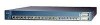
... as servers, routers, and other network devices. A feature specific to the Catalyst 3524-PWR XL switch is its ability to provide inline power to Cisco IP Phones. (Phone adapters are stackable 10/100 Ethernet switches to the Catalyst 3524-PWR XL 10/100 switch ports.) Figure 1-1 shows the switch models in the series, and Table 1-1 and Table 1-2 list...
... as servers, routers, and other network devices. A feature specific to the Catalyst 3524-PWR XL switch is its ability to provide inline power to Cisco IP Phones. (Phone adapters are stackable 10/100 Ethernet switches to the Catalyst 3524-PWR XL 10/100 switch ports.) Figure 1-1 shows the switch models in the series, and Table 1-1 and Table 1-2 list...

Installation Guide
Page 32
... and duplex autonegotiation, compliant with IEEE 802.3u. However, the Catalyst 3524-PWR XL 10/100 ports can: • Provide -48V DC power to operate in Appendix B, "Connector and Cable Specifications." The 10/100 switch ports can be sure that both devices support and full-duplex transmission...When you can sense the speed and duplex settings of half duplex, full duplex, 10 Mbps, or 100 Mbps. Cisco IP Phones-connected to the Cisco IOS Desktop Switching Software Configuration Guide for each 10/100 port: Auto and Never. Front-Panel Description Chapter 1 Product Overview • ...
... and duplex autonegotiation, compliant with IEEE 802.3u. However, the Catalyst 3524-PWR XL 10/100 ports can: • Provide -48V DC power to operate in Appendix B, "Connector and Cable Specifications." The 10/100 switch ports can be sure that both devices support and full-duplex transmission...When you can sense the speed and duplex settings of half duplex, full duplex, 10 Mbps, or 100 Mbps. Cisco IP Phones-connected to the Cisco IOS Desktop Switching Software Configuration Guide for each 10/100 port: Auto and Never. Front-Panel Description Chapter 1 Product Overview • ...

Installation Guide
Page 47
Cisco RPS Connector Specific Cisco RPS models support specific Catalyst 3500 XL switches: • Cisco RPS 600 (model PWR600-AC-RPS)-Supports the Catalyst 3512, 3524, 3548, and 3508 XL switches • Cisco RPS 300 (model PWR300-AC-RPS)-Supports the Catalyst 3524-PWR XL switch RPS Connector on the Cisco RPS 600, refer to the Cisco Redundant Power System Hardware Installation Guide. 78-6456...
Cisco RPS Connector Specific Cisco RPS models support specific Catalyst 3500 XL switches: • Cisco RPS 600 (model PWR600-AC-RPS)-Supports the Catalyst 3512, 3524, 3548, and 3508 XL switches • Cisco RPS 300 (model PWR300-AC-RPS)-Supports the Catalyst 3524-PWR XL switch RPS Connector on the Cisco RPS 600, refer to the Cisco Redundant Power System Hardware Installation Guide. 78-6456...

Installation Guide
Page 48
... a total output power of four web-based applications that adapter from Cisco. Although it supports up to six switches. For console port and adapter pinout information, see the "Cable and Adapter Specifications" section on page B-4. It provides a fully-redundant power source for these applications. 1-24 Catalyst 3500 Series XL Hardware Installation Guide 78-6456-04
... a total output power of four web-based applications that adapter from Cisco. Although it supports up to six switches. For console port and adapter pinout information, see the "Cable and Adapter Specifications" section on page B-4. It provides a fully-redundant power source for these applications. 1-24 Catalyst 3500 Series XL Hardware Installation Guide 78-6456-04

Installation Guide
Page 65
Statement 256 Installation Guidelines When determining where to place the switch, be used . For specific cable lengths, refer to the documents that came with the GigaStack GBIC. • Operating environment is within the ranges listed in Appendix A, "Technical Specifications." 78-6456-04 Catalyst 3500 Series XL Hardware Installation Guide 2-7 Class A equipment is designed for typical...
Statement 256 Installation Guidelines When determining where to place the switch, be used . For specific cable lengths, refer to the documents that came with the GigaStack GBIC. • Operating environment is within the ranges listed in Appendix A, "Technical Specifications." 78-6456-04 Catalyst 3500 Series XL Hardware Installation Guide 2-7 Class A equipment is designed for typical...

Installation Guide
Page 81
... the "Cable and Adapter Specifications" section on the GigaStack GBIC connections and configuration scenarios, see the Catalyst GigaStack Gigabit Interface Converter Hardware Installation Guide. The terminal-emulation software-frequently a PC application such as Hyperterminal or Procomm Plus-makes communication between the switch and your PC- See the Cisco IOS Desktop Switching Software Configuration Guide for...
... the "Cable and Adapter Specifications" section on the GigaStack GBIC connections and configuration scenarios, see the Catalyst GigaStack Gigabit Interface Converter Hardware Installation Guide. The terminal-emulation software-frequently a PC application such as Hyperterminal or Procomm Plus-makes communication between the switch and your PC- See the Cisco IOS Desktop Switching Software Configuration Guide for...

Installation Guide
Page 84
...the switch, and press Return: 2-26 Catalyst 3500 Series XL Hardware Installation Guide 78-6456-04 Use the supplied rollover cable and DB-9 adapter to connect a PC to restart the setup program. For console port and adapter pinout information, see the "Cable and Adapter Specifications" ...Y at the prompt: Continue with configuration dialog? [yes/no parity. Enter setup, and press Return to the switch console port. You can order a kit (part number ACS-DSBUASYN=) containing that adapter from Cisco. The data characteristics are 9600 baud, 8 data bits, 1 stop bit, and no ]: y If this ...
...the switch, and press Return: 2-26 Catalyst 3500 Series XL Hardware Installation Guide 78-6456-04 Use the supplied rollover cable and DB-9 adapter to connect a PC to restart the setup program. For console port and adapter pinout information, see the "Cable and Adapter Specifications" ...Y at the prompt: Continue with configuration dialog? [yes/no parity. Enter setup, and press Return to the switch console port. You can order a kit (part number ACS-DSBUASYN=) containing that adapter from Cisco. The data characteristics are 9600 baud, 8 data bits, 1 stop bit, and no ]: y If this ...

Installation Guide
Page 97
...-6456-04 Table A-1, Table A-2, and Table A-3, list the technical specifications for the Catalyst 3508G XL Switch Environmental Ranges Operating temperature Storage temperature Operating humidity Operating altitude Storage altitude Power Requirements AC input voltage DC input voltages Power consumption ...@14A, +12V @3A 82.2W 280 Btus per hour 12 lb (5.45 kg) 1.75 x 16 x 17.5 in. (4.45 x 40.46 x 44.45 cm) Catalyst 3500 Series XL Hardware Installation Guide A-1 Table A-1 Technical Specifications for the Catalyst 3500 series XL switches. Table A-4 lists the regulatory agency approvals.
...-6456-04 Table A-1, Table A-2, and Table A-3, list the technical specifications for the Catalyst 3508G XL Switch Environmental Ranges Operating temperature Storage temperature Operating humidity Operating altitude Storage altitude Power Requirements AC input voltage DC input voltages Power consumption ...@14A, +12V @3A 82.2W 280 Btus per hour 12 lb (5.45 kg) 1.75 x 16 x 17.5 in. (4.45 x 40.46 x 44.45 cm) Catalyst 3500 Series XL Hardware Installation Guide A-1 Table A-1 Technical Specifications for the Catalyst 3500 series XL switches. Table A-4 lists the regulatory agency approvals.

Installation Guide
Page 98
Appendix A Technical Specifications Table A-2 Technical Specifications for the Catalyst 3512, 3524, and 3548 XL Switches Catalyst 3512 XL Catalyst 3524 XL Catalyst 3548 XL Environmental Ranges Operating temperature 32 to 113°F (0 to 45°C) 32 to 113°F (0 to 45°C) 32 to 113°F (0 to ....82 x 17.5 in. 1.73 x 15.34 x 17.5 in D x W) (4.45 x 30.02 x 44.45 cm) (4.45 x 30.02 x 44.45 cm) (4.39 x 39.0 x 44.45 cm) Catalyst 3500 Series XL Hardware Installation Guide A-2 78-6456-04
Appendix A Technical Specifications Table A-2 Technical Specifications for the Catalyst 3512, 3524, and 3548 XL Switches Catalyst 3512 XL Catalyst 3524 XL Catalyst 3548 XL Environmental Ranges Operating temperature 32 to 113°F (0 to 45°C) 32 to 113°F (0 to 45°C) 32 to 113°F (0 to ....82 x 17.5 in. 1.73 x 15.34 x 17.5 in D x W) (4.45 x 30.02 x 44.45 cm) (4.45 x 30.02 x 44.45 cm) (4.39 x 39.0 x 44.45 cm) Catalyst 3500 Series XL Hardware Installation Guide A-2 78-6456-04

Installation Guide
Page 99
Table A-4 Catalyst 3500 Series XL Agency Approvals Safety EMC UL to UL 1950, Third Edition...x D) 1.75 x 11.82 x 17.5 in. (4.45 x 30.02 x 44.45 cm) 1. Appendix A Technical Specifications Table A-3 Technical Specifications for the Catalyst 3524-PWR XL Switch Environmental Ranges Operating temperature 32 to 113°F (0 to 45°C) Storage temperature -4 to 149°F (-10 to 65°...autoranging) 50 to NOM-019-SCFI CE Marking CE Marking 78-6456-04 Catalyst 3500 Series XL Hardware Installation Guide A-3 The actual power consumption depends on the number of IP phones connected....
Table A-4 Catalyst 3500 Series XL Agency Approvals Safety EMC UL to UL 1950, Third Edition...x D) 1.75 x 11.82 x 17.5 in. (4.45 x 30.02 x 44.45 cm) 1. Appendix A Technical Specifications Table A-3 Technical Specifications for the Catalyst 3524-PWR XL Switch Environmental Ranges Operating temperature 32 to 113°F (0 to 45°C) Storage temperature -4 to 149°F (-10 to 65°...autoranging) 50 to NOM-019-SCFI CE Marking CE Marking 78-6456-04 Catalyst 3500 Series XL Hardware Installation Guide A-3 The actual power consumption depends on the number of IP phones connected....

Installation Guide
Page 100
Appendix A Technical Specifications Catalyst 3500 Series XL Hardware Installation Guide A-4 78-6456-04
Appendix A Technical Specifications Catalyst 3500 Series XL Hardware Installation Guide A-4 78-6456-04

Installation Guide
Page 101
These ports have an X. 78-6456-04 Catalyst 3500 Series XL Hardware Installation Guide B-1 When connecting the 10/100 ports to compatible workstations, servers, routers, and Cisco IP Phones, you use a crossover cable. (Figure B-4 illustrates the crossover cable schematics.) Note Use a straight-through cable to connect two... adapter can be attached to the port. Figure B-1 shows the pinout. When connecting to other devices. APPENDIX B Connector and Cable Specifications This appendix describes the Catalyst 3500 XL switch ports and the cables and adapters that you use to connect the...
These ports have an X. 78-6456-04 Catalyst 3500 Series XL Hardware Installation Guide B-1 When connecting the 10/100 ports to compatible workstations, servers, routers, and Cisco IP Phones, you use a crossover cable. (Figure B-4 illustrates the crossover cable schematics.) Note Use a straight-through cable to connect two... adapter can be attached to the port. Figure B-1 shows the pinout. When connecting to other devices. APPENDIX B Connector and Cable Specifications This appendix describes the Catalyst 3500 XL switch ports and the cables and adapters that you use to connect the...

Installation Guide
Page 102
Connector Specifications Appendix B Connector and Cable Specifications Figure B-1 10/100 Port Pinouts Pin Label 1 RD+ 2 RD- 3 TD+ 4 NC 5 NC 6 TD- 7 NC 8 NC 12345678 H5318 1000BaseX Ports 1000BaseX ports use duplex SC connectors, as shown in Figure B-2. Figure B-2 1000BaseX SC Connector H8707 Tx Rx Catalyst 3500 Series XL Hardware Installation Guide B-2 78-6456-04
Connector Specifications Appendix B Connector and Cable Specifications Figure B-1 10/100 Port Pinouts Pin Label 1 RD+ 2 RD- 3 TD+ 4 NC 5 NC 6 TD- 7 NC 8 NC 12345678 H5318 1000BaseX Ports 1000BaseX ports use duplex SC connectors, as shown in Figure B-2. Figure B-2 1000BaseX SC Connector H8707 Tx Rx Catalyst 3500 Series XL Hardware Installation Guide B-2 78-6456-04

Installation Guide
Page 103
...pinout information, see Table B-1 and Table B-2. 78-6456-04 Catalyst 3500 Series XL Hardware Installation Guide B-3 The supplied RJ-45-to... the GigaStack GBIC. You can order a kit (part number ACS-DSBUASYN=) containing that adapter from Cisco. Console Port The console port uses an 8-pin RJ-45 connector, described in Figure B-3. Caution...the switch console port to a console PC. Figure B-3 GigaStack Connector 22084 The GigaStack GBIC cables are used to connect the console port of the switch to a terminal. Appendix B Connector and Cable Specifications Connector Specifications ...
...pinout information, see Table B-1 and Table B-2. 78-6456-04 Catalyst 3500 Series XL Hardware Installation Guide B-3 The supplied RJ-45-to... the GigaStack GBIC. You can order a kit (part number ACS-DSBUASYN=) containing that adapter from Cisco. Console Port The console port uses an 8-pin RJ-45 connector, described in Figure B-3. Caution...the switch console port to a console PC. Figure B-3 GigaStack Connector 22084 The GigaStack GBIC cables are used to connect the console port of the switch to a terminal. Appendix B Connector and Cable Specifications Connector Specifications ...

Installation Guide
Page 104
Figure B-4 Crossover Cable Schematic Switch 3 TD+ 6 TD- H5578 Catalyst 3500 Series XL Hardware Installation Guide B-4 78-6456-04 Switch 3 TD+ 6 TD- 1 RD+ 2 RD- 1 RD+ 2 RD- Switch 3 RD+ 6 RD- 1 RD+ 2 RD- 1 TD+ 2 TD- H5579 Figure B-5 Straight-Through Cable Schematic Switch 3 TD+ 6 TD- Cable and Adapter Specifications Appendix B Connector and Cable Specifications Cable and Adapter Specifications Crossover and Straight-Through Cable Pinouts The schematics of crossover and straight-through cables are shown in Figure B-4 and Figure B-5.
Figure B-4 Crossover Cable Schematic Switch 3 TD+ 6 TD- H5578 Catalyst 3500 Series XL Hardware Installation Guide B-4 78-6456-04 Switch 3 TD+ 6 TD- 1 RD+ 2 RD- 1 RD+ 2 RD- Switch 3 RD+ 6 RD- 1 RD+ 2 RD- 1 TD+ 2 TD- H5579 Figure B-5 Straight-Through Cable Schematic Switch 3 TD+ 6 TD- Cable and Adapter Specifications Appendix B Connector and Cable Specifications Cable and Adapter Specifications Crossover and Straight-Through Cable Pinouts The schematics of crossover and straight-through cables are shown in Figure B-4 and Figure B-5.

Installation Guide
Page 105
... the pin on the outside of the left plug should be the same color. Pin 8 H10632 78-6456-04 Catalyst 3500 Series XL Hardware Installation Guide B-5 Appendix B Connector and Cable Specifications Cable and Adapter Specifications Rollover Cable and Adapter Pinouts Identifying a Rollover Cable To identify a rollover cable, compare the two modular ends of...
... the pin on the outside of the left plug should be the same color. Pin 8 H10632 78-6456-04 Catalyst 3500 Series XL Hardware Installation Guide B-5 Appendix B Connector and Cable Specifications Cable and Adapter Specifications Rollover Cable and Adapter Pinouts Identifying a Rollover Cable To identify a rollover cable, compare the two modular ends of...

Installation Guide
Page 106
...RJ-45-to-RJ-45 rollover cable, and the RJ-45-to a PC. Figure B-7 Connecting the Console Port to a PC PC Catalyst 3500 series XL switch 22003 RJ-45-to-RJ-45 rollover cable RJ-45-to-DB-9 adapter (labeled TERMINAL) Table B-1 Console Port Signaling and Cabling Using... 2 7 TxD 3 6 GND 4 5 GND 5 4 RxD 6 3 Not connected 7 2 CTS 8 1 RJ-45-to a PC running terminal-emulation software. Cable and Adapter Specifications Appendix B Connector and Cable Specifications Connecting to a PC Use the supplied thin, flat, RJ-45-to-RJ-45 rollover cable and RJ-45-to-DB-9 female DTE adapter...
...RJ-45-to-RJ-45 rollover cable, and the RJ-45-to a PC. Figure B-7 Connecting the Console Port to a PC PC Catalyst 3500 series XL switch 22003 RJ-45-to-RJ-45 rollover cable RJ-45-to-DB-9 adapter (labeled TERMINAL) Table B-1 Console Port Signaling and Cabling Using... 2 7 TxD 3 6 GND 4 5 GND 5 4 RxD 6 3 Not connected 7 2 CTS 8 1 RJ-45-to a PC running terminal-emulation software. Cable and Adapter Specifications Appendix B Connector and Cable Specifications Connecting to a PC Use the supplied thin, flat, RJ-45-to-RJ-45 rollover cable and RJ-45-to-DB-9 female DTE adapter...