
Installation Guide
Page 2
... You can radiate radio-frequency energy and, if not installed and used in accordance with the specifications in part 15 of a program developed by Cisco Systems, Inc. The Cisco implementation of TCP header compression is no longer complying with FCC requirements for Class A or Class... when the equipment is likely to comply with radio and television reception. Modifying the equipment without Cisco's written authorization may radiate radio-frequency energy. THE SPECIFICATIONS AND INFORMATION REGARDING THE PRODUCTS IN THIS MANUAL ARE SUBJECT TO CHANGE WITHOUT NOTICE. Operation of ...
... You can radiate radio-frequency energy and, if not installed and used in accordance with the specifications in part 15 of a program developed by Cisco Systems, Inc. The Cisco implementation of TCP header compression is no longer complying with FCC requirements for Class A or Class... when the equipment is likely to comply with radio and television reception. Modifying the equipment without Cisco's written authorization may radiate radio-frequency energy. THE SPECIFICATIONS AND INFORMATION REGARDING THE PRODUCTS IN THIS MANUAL ARE SUBJECT TO CHANGE WITHOUT NOTICE. Operation of ...

Installation Guide
Page 8
... B-1 1000BaseX Ports B-2 Gigastack Port B-3 Console Port B-3 Cable and Adapter Specifications B-4 Crossover and Straight-Through Cable Pinouts B-4 Rollover Cable and Adapter Pinouts B-5 Identifying a Rollover Cable B-5 Connecting to a PC B-6 Connecting to a Terminal B-7 Translated Safety Warnings C-1 Attaching the Cisco RPS (model PWR600-AC-RPS) C-2 Attaching the Cisco RPS (model PWR300-AC-RPS-N1) C-4 Service Personnel Warning...
... B-1 1000BaseX Ports B-2 Gigastack Port B-3 Console Port B-3 Cable and Adapter Specifications B-4 Crossover and Straight-Through Cable Pinouts B-4 Rollover Cable and Adapter Pinouts B-5 Identifying a Rollover Cable B-5 Connecting to a PC B-6 Connecting to a Terminal B-7 Translated Safety Warnings C-1 Attaching the Cisco RPS (model PWR600-AC-RPS) C-2 Attaching the Cisco RPS (model PWR300-AC-RPS-N1) C-4 Service Personnel Warning...

Installation Guide
Page 12
...Catalyst 3500 Series XL Hardware Installation Guide xii 78-6456-04 Chapter 3, "Troubleshooting," describes how to identify and resolve some of the warnings in boldface screen font. • Nonprinting characters, such as passwords or tabs, are installing the switch. Appendix B, "Connector and Cable Specifications...that might arise when you are in italic. It also describes how to the switch. Appendix A, "Technical Specifications," lists the physical and environmental specifications for installing a switch on a rack, wall, table, or shelf. Appendix C, "Translated Safety Warnings,"...
...Catalyst 3500 Series XL Hardware Installation Guide xii 78-6456-04 Chapter 3, "Troubleshooting," describes how to identify and resolve some of the warnings in boldface screen font. • Nonprinting characters, such as passwords or tabs, are installing the switch. Appendix B, "Connector and Cable Specifications...that might arise when you are in italic. It also describes how to the switch. Appendix A, "Technical Specifications," lists the physical and environmental specifications for installing a switch on a rack, wall, table, or shelf. Appendix C, "Translated Safety Warnings,"...

Installation Guide
Page 25
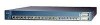
... specific to the Catalyst 3524-PWR XL switch is its ability to provide inline power to Cisco IP Phones. (Phone adapters are stackable 10/100 Ethernet switches to the Catalyst 3524-PWR XL 10/100 switch ports.) Figure 1-1 shows the switch models in different network topologies Features The Catalyst 3500 series XL switches-also referred to as Catalyst 3500 XL switches-are...
... specific to the Catalyst 3524-PWR XL switch is its ability to provide inline power to Cisco IP Phones. (Phone adapters are stackable 10/100 Ethernet switches to the Catalyst 3524-PWR XL 10/100 switch ports.) Figure 1-1 shows the switch models in different network topologies Features The Catalyst 3500 series XL switches-also referred to as Catalyst 3500 XL switches-are...

Installation Guide
Page 32
... advertises its own capabilities. The 10/100 ports on the Catalyst 3512, 3524, and 3548 XL switches-must be explicitly set to the Cisco IOS Desktop Switching Software Configuration Guide for ports operating at 100 Mbps. Refer to operate in Appendix B, "Connector and Cable Specifications." CMS and the CLI provide two inline power settings for...
... advertises its own capabilities. The 10/100 ports on the Catalyst 3512, 3524, and 3548 XL switches-must be explicitly set to the Cisco IOS Desktop Switching Software Configuration Guide for ports operating at 100 Mbps. Refer to operate in Appendix B, "Connector and Cable Specifications." CMS and the CLI provide two inline power settings for...

Installation Guide
Page 47
... connector to an AC power outlet. Cisco RPS Connector Specific Cisco RPS models support specific Catalyst 3500 XL switches: • Cisco RPS 600 (model PWR600-AC-RPS)-Supports the Catalyst 3512, 3524, 3548, and 3508 XL switches • Cisco RPS 300 (model PWR300-AC-RPS)-Supports the Catalyst 3524-PWR XL switch RPS Connector on the Cisco RPS 600, refer to the RPS...
... connector to an AC power outlet. Cisco RPS Connector Specific Cisco RPS models support specific Catalyst 3500 XL switches: • Cisco RPS 600 (model PWR600-AC-RPS)-Supports the Catalyst 3512, 3524, 3548, and 3508 XL switches • Cisco RPS 300 (model PWR300-AC-RPS)-Supports the Catalyst 3524-PWR XL switch RPS Connector on the Cisco RPS 600, refer to the RPS...

Installation Guide
Page 48
...to create, configure, and monitor clusters. For console port and adapter pinout information, see the "Cable and Adapter Specifications" section on the Catalyst 3524-PWR XL Switch The Cisco RPS 300 (model PWR300-AC-RPS) has two output levels: -48V and 12V with a total output power...View, and Cluster Manager applications to six switches, it supports up to the Cisco IOS Desktop Switching Software Configuration Guide and the online help for these applications. 1-24 Catalyst 3500 Series XL Hardware Installation Guide 78-6456-04 Warning Attach only the Cisco RPS (model PWR300-AC-RPS) to...
...to create, configure, and monitor clusters. For console port and adapter pinout information, see the "Cable and Adapter Specifications" section on the Catalyst 3524-PWR XL Switch The Cisco RPS 300 (model PWR300-AC-RPS) has two output levels: -48V and 12V with a total output power...View, and Cluster Manager applications to six switches, it supports up to the Cisco IOS Desktop Switching Software Configuration Guide and the online help for these applications. 1-24 Catalyst 3500 Series XL Hardware Installation Guide 78-6456-04 Warning Attach only the Cisco RPS (model PWR300-AC-RPS) to...

Installation Guide
Page 65
...Chapter 2 Installing and Starting Up the Switch Hungary Preparing for which special conditions of installation and protection distance are used and installed properly according to the Hungarian EMC Class A requirements (MSZEN55022). For specific cable lengths, refer to the documents ...cable lengths from the switch to the connected devices are up to 1 meter. Class A equipment is designed for typical commercial establishments for Installation Warning This equipment is within the ranges listed in Appendix A, "Technical Specifications." 78-6456-04 Catalyst 3500 Series XL Hardware...
...Chapter 2 Installing and Starting Up the Switch Hungary Preparing for which special conditions of installation and protection distance are used and installed properly according to the Hungarian EMC Class A requirements (MSZEN55022). For specific cable lengths, refer to the documents ...cable lengths from the switch to the connected devices are up to 1 meter. Class A equipment is designed for typical commercial establishments for Installation Warning This equipment is within the ranges listed in Appendix A, "Technical Specifications." 78-6456-04 Catalyst 3500 Series XL Hardware...

Installation Guide
Page 81
... these steps to connect the PC or terminal to the switch: Step 1 Step 2 Be sure that adapter from Cisco. For console port and adapter pinout information, see the "Cable and Adapter Specifications" section on the GigaStack GBIC connections and configuration scenarios, see the Catalyst GigaStack Gigabit Interface Converter Hardware Installation Guide. The PC or...
... these steps to connect the PC or terminal to the switch: Step 1 Step 2 Be sure that adapter from Cisco. For console port and adapter pinout information, see the "Cable and Adapter Specifications" section on the GigaStack GBIC connections and configuration scenarios, see the Catalyst GigaStack Gigabit Interface Converter Hardware Installation Guide. The PC or...

Installation Guide
Page 84
... the switch, and press Return: 2-26 Catalyst 3500 Series XL Hardware Installation Guide 78-6456-04 You can order a kit (part number ACS-DSBUASYN=) containing that adapter from Cisco. Assigning Switch Information Chapter 2 Installing and Starting Up the Switch Default gateway... (router Enable secret password Use this prompt does not appear, enter enable, and press Return. Use the supplied rollover cable and DB-9 adapter to connect a PC to restart the setup program. For console port and adapter pinout information, see the "Cable and Adapter Specifications...
... the switch, and press Return: 2-26 Catalyst 3500 Series XL Hardware Installation Guide 78-6456-04 You can order a kit (part number ACS-DSBUASYN=) containing that adapter from Cisco. Assigning Switch Information Chapter 2 Installing and Starting Up the Switch Default gateway... (router Enable secret password Use this prompt does not appear, enter enable, and press Return. Use the supplied rollover cable and DB-9 adapter to connect a PC to restart the setup program. For console port and adapter pinout information, see the "Cable and Adapter Specifications...

Installation Guide
Page 97
Table A-4 lists the regulatory agency approvals. Table A-1 Technical Specifications for the Catalyst 3500 series XL switches. A A P P E N D I X Technical Specifications 78-6456-04 Table A-1, Table A-2, and Table A-3, list the technical specifications for the Catalyst 3508G XL Switch Environmental Ranges Operating temperature Storage temperature Operating humidity Operating altitude Storage altitude Power Requirements AC input voltage ... @3A 82.2W 280 Btus per hour 12 lb (5.45 kg) 1.75 x 16 x 17.5 in. (4.45 x 40.46 x 44.45 cm) Catalyst 3500 Series XL Hardware Installation Guide A-1
Table A-4 lists the regulatory agency approvals. Table A-1 Technical Specifications for the Catalyst 3500 series XL switches. A A P P E N D I X Technical Specifications 78-6456-04 Table A-1, Table A-2, and Table A-3, list the technical specifications for the Catalyst 3508G XL Switch Environmental Ranges Operating temperature Storage temperature Operating humidity Operating altitude Storage altitude Power Requirements AC input voltage ... @3A 82.2W 280 Btus per hour 12 lb (5.45 kg) 1.75 x 16 x 17.5 in. (4.45 x 40.46 x 44.45 cm) Catalyst 3500 Series XL Hardware Installation Guide A-1

Installation Guide
Page 98
Appendix A Technical Specifications Table A-2 Technical Specifications for the Catalyst 3512, 3524, and 3548 XL Switches Catalyst 3512 XL Catalyst 3524 XL Catalyst 3548 XL Environmental Ranges Operating temperature 32 to 113°F (0 to 45°C) 32 to 113°F (0 to 45°C) 32 to 113°F (0 to ....82 x 17.5 in. 1.73 x 15.34 x 17.5 in D x W) (4.45 x 30.02 x 44.45 cm) (4.45 x 30.02 x 44.45 cm) (4.39 x 39.0 x 44.45 cm) Catalyst 3500 Series XL Hardware Installation Guide A-2 78-6456-04
Appendix A Technical Specifications Table A-2 Technical Specifications for the Catalyst 3512, 3524, and 3548 XL Switches Catalyst 3512 XL Catalyst 3524 XL Catalyst 3548 XL Environmental Ranges Operating temperature 32 to 113°F (0 to 45°C) 32 to 113°F (0 to 45°C) 32 to 113°F (0 to ....82 x 17.5 in. 1.73 x 15.34 x 17.5 in D x W) (4.45 x 30.02 x 44.45 cm) (4.45 x 30.02 x 44.45 cm) (4.39 x 39.0 x 44.45 cm) Catalyst 3500 Series XL Hardware Installation Guide A-2 78-6456-04

Installation Guide
Page 99
Appendix A Technical Specifications Table A-3 Technical Specifications for the Catalyst 3524-PWR XL Switch Environmental Ranges Operating temperature 32 to 113°F (0 to 45°C) Storage temperature -4 to 149°F (-10 to 65°C) Operating humidity 10 to 85% (... Series XL Hardware Installation Guide A-3 The actual power consumption depends on the number of IP phones connected. 325W represents 24 IP phones connected. Table A-4 Catalyst 3500 Series XL Agency Approvals Safety EMC UL to UL 1950, Third Edition FCC Part 15 Class A c-UL to CAN/CSA 22.2 No. 950-95, ...
Appendix A Technical Specifications Table A-3 Technical Specifications for the Catalyst 3524-PWR XL Switch Environmental Ranges Operating temperature 32 to 113°F (0 to 45°C) Storage temperature -4 to 149°F (-10 to 65°C) Operating humidity 10 to 85% (... Series XL Hardware Installation Guide A-3 The actual power consumption depends on the number of IP phones connected. 325W represents 24 IP phones connected. Table A-4 Catalyst 3500 Series XL Agency Approvals Safety EMC UL to UL 1950, Third Edition FCC Part 15 Class A c-UL to CAN/CSA 22.2 No. 950-95, ...

Installation Guide
Page 100
Appendix A Technical Specifications Catalyst 3500 Series XL Hardware Installation Guide A-4 78-6456-04
Appendix A Technical Specifications Catalyst 3500 Series XL Hardware Installation Guide A-4 78-6456-04

Installation Guide
Page 101
...both ports are designated with internal crossovers, as indicated by an X in the port name. APPENDIX B Connector and Cable Specifications This appendix describes the Catalyst 3500 XL switch ports and the cables and adapters that you use a crossover cable. (Figure B-4 illustrates the crossover cable schematics.) Note...use to connect the switch to connect two ports when both ports do not have their transmit (TD) and receive (RD) signals internally crossed so that a straight-through cable and adapter can be attached to compatible workstations, servers, routers, and Cisco IP Phones, you...
...both ports are designated with internal crossovers, as indicated by an X in the port name. APPENDIX B Connector and Cable Specifications This appendix describes the Catalyst 3500 XL switch ports and the cables and adapters that you use a crossover cable. (Figure B-4 illustrates the crossover cable schematics.) Note...use to connect the switch to connect two ports when both ports do not have their transmit (TD) and receive (RD) signals internally crossed so that a straight-through cable and adapter can be attached to compatible workstations, servers, routers, and Cisco IP Phones, you...

Installation Guide
Page 102
Figure B-2 1000BaseX SC Connector H8707 Tx Rx Catalyst 3500 Series XL Hardware Installation Guide B-2 78-6456-04 Connector Specifications Appendix B Connector and Cable Specifications Figure B-1 10/100 Port Pinouts Pin Label 1 RD+ 2 RD- 3 TD+ 4 NC 5 NC 6 TD- 7 NC 8 NC 12345678 H5318 1000BaseX Ports 1000BaseX ports use duplex SC connectors, as shown in Figure B-2.
Figure B-2 1000BaseX SC Connector H8707 Tx Rx Catalyst 3500 Series XL Hardware Installation Guide B-2 78-6456-04 Connector Specifications Appendix B Connector and Cable Specifications Figure B-1 10/100 Port Pinouts Pin Label 1 RD+ 2 RD- 3 TD+ 4 NC 5 NC 6 TD- 7 NC 8 NC 12345678 H5318 1000BaseX Ports 1000BaseX ports use duplex SC connectors, as shown in Figure B-2.

Installation Guide
Page 103
...if you want to connect the switch console port to a console PC... Appendix B Connector and Cable Specifications Connector Specifications Gigastack Port The GigaStack Gigabit ...Interface Converter (GBIC) uses proprietary connectors, as shown in Table B-1 and Table B-2. For console port and adapter pinout information, see Table B-1 and Table B-2. 78-6456-04 Catalyst... 3500 Series XL Hardware Installation Guide B-3 Figure B-3 GigaStack Connector 22084 The GigaStack GBIC cables are used to connect the console port of the switch...
...if you want to connect the switch console port to a console PC... Appendix B Connector and Cable Specifications Connector Specifications Gigastack Port The GigaStack Gigabit ...Interface Converter (GBIC) uses proprietary connectors, as shown in Table B-1 and Table B-2. For console port and adapter pinout information, see Table B-1 and Table B-2. 78-6456-04 Catalyst... 3500 Series XL Hardware Installation Guide B-3 Figure B-3 GigaStack Connector 22084 The GigaStack GBIC cables are used to connect the console port of the switch...

Installation Guide
Page 104
Figure B-4 Crossover Cable Schematic Switch 3 TD+ 6 TD- Switch 3 TD+ 6 TD- 1 RD+ 2 RD- 1 RD+ 2 RD- H5578 Catalyst 3500 Series XL Hardware Installation Guide B-4 78-6456-04 Cable and Adapter Specifications Appendix B Connector and Cable Specifications Cable and Adapter Specifications Crossover and Straight-Through Cable Pinouts The schematics of crossover and straight-through cables are shown in Figure B-4 and Figure B-5. H5579 Figure B-5 Straight-Through Cable Schematic Switch 3 TD+ 6 TD- Switch 3 RD+ 6 RD- 1 RD+ 2 RD- 1 TD+ 2 TD-
Figure B-4 Crossover Cable Schematic Switch 3 TD+ 6 TD- Switch 3 TD+ 6 TD- 1 RD+ 2 RD- 1 RD+ 2 RD- H5578 Catalyst 3500 Series XL Hardware Installation Guide B-4 78-6456-04 Cable and Adapter Specifications Appendix B Connector and Cable Specifications Cable and Adapter Specifications Crossover and Straight-Through Cable Pinouts The schematics of crossover and straight-through cables are shown in Figure B-4 and Figure B-5. H5579 Figure B-5 Straight-Through Cable Schematic Switch 3 TD+ 6 TD- Switch 3 RD+ 6 RD- 1 RD+ 2 RD- 1 TD+ 2 TD-

Installation Guide
Page 105
Appendix B Connector and Cable Specifications Cable and Adapter Specifications Rollover Cable and Adapter Pinouts Identifying a Rollover Cable To identify a rollover cable, compare the two modular ends of the left plug should be the same ... outside of the right plug (see Figure B-6). Hold the cable ends side-by-side, with the tab at the back. Pin 8 H10632 78-6456-04 Catalyst 3500 Series XL Hardware Installation Guide B-5 The wire connected to the pin on the other connector should be the same color as the wire connected...
Appendix B Connector and Cable Specifications Cable and Adapter Specifications Rollover Cable and Adapter Pinouts Identifying a Rollover Cable To identify a rollover cable, compare the two modular ends of the left plug should be the same ... outside of the right plug (see Figure B-6). Hold the cable ends side-by-side, with the tab at the back. Pin 8 H10632 78-6456-04 Catalyst 3500 Series XL Hardware Installation Guide B-5 The wire connected to the pin on the other connector should be the same color as the wire connected...

Installation Guide
Page 106
... shows how to connect the console port to -DB-9 female DTE adapter. Figure B-7 Connecting the Console Port to a PC PC Catalyst 3500 series XL switch 22003 RJ-45-to-RJ-45 rollover cable RJ-45-to-DB-9 adapter (labeled TERMINAL) Table B-1 Console Port Signaling and Cabling ... 3 6 GND 4 5 GND 5 4 RxD 6 3 Not connected 7 2 CTS 8 1 RJ-45-to a PC running terminal-emulation software. Cable and Adapter Specifications Appendix B Connector and Cable Specifications Connecting to a PC Use the supplied thin, flat, RJ-45-to-RJ-45 rollover cable and RJ-45-to-DB-9 female DTE adapter...
... shows how to connect the console port to -DB-9 female DTE adapter. Figure B-7 Connecting the Console Port to a PC PC Catalyst 3500 series XL switch 22003 RJ-45-to-RJ-45 rollover cable RJ-45-to-DB-9 adapter (labeled TERMINAL) Table B-1 Console Port Signaling and Cabling ... 3 6 GND 4 5 GND 5 4 RxD 6 3 Not connected 7 2 CTS 8 1 RJ-45-to a PC running terminal-emulation software. Cable and Adapter Specifications Appendix B Connector and Cable Specifications Connecting to a PC Use the supplied thin, flat, RJ-45-to-RJ-45 rollover cable and RJ-45-to-DB-9 female DTE adapter...