
Installation Guide
Page 29
... (VSM) Front-Panel Description The front panel of the Catalyst 3508G XL switch (Figure 1-2) has eight 1000BaseX GBIC module slots but no 10/100 ports. Chapter 1 Product Overview Front-Panel Description Table 1-2 Catalyst 3512, 3524, 3524-PWR, and 3548 XL Features (continued) Feature Description (continued) Management • Cisco IOS CLI through the console port or Telnet •...
... (VSM) Front-Panel Description The front panel of the Catalyst 3508G XL switch (Figure 1-2) has eight 1000BaseX GBIC module slots but no 10/100 ports. Chapter 1 Product Overview Front-Panel Description Table 1-2 Catalyst 3512, 3524, 3524-PWR, and 3548 XL Features (continued) Feature Description (continued) Management • Cisco IOS CLI through the console port or Telnet •...

Installation Guide
Page 31
... port 4, and so on the Catalyst 3512, 3524, 3524-PWR, and 3548 XL switches are grouped in Figure 1-3, Figure 1-4, Figure 1-5, and Figure 1-6, ports 1 and 2 are the left-most pair. The 10/100 switch ports can connect, up to any compatible network device: • 10BaseT-compatible devices such as workstations, Cisco IP Phones, and hubs through standard...
... port 4, and so on the Catalyst 3512, 3524, 3524-PWR, and 3548 XL switches are grouped in Figure 1-3, Figure 1-4, Figure 1-5, and Figure 1-6, ports 1 and 2 are the left-most pair. The 10/100 switch ports can connect, up to any compatible network device: • 10BaseT-compatible devices such as workstations, Cisco IP Phones, and hubs through standard...

Installation Guide
Page 32
...the 10/100 ports on the Catalyst 3512, 3524, 3524-PWR, and 3548 XL switches provide protocol support for Cisco IP Phones. CMS and the CLI provide two inline power settings for inline power on a port, the port Catalyst 3500 Series XL Hardware Installation Guide 1-8 78-6456-... and other switches through , twisted-pair cable. When connecting the switch to the Cisco IOS Desktop Switching Software Configuration Guide for 100BaseTX traffic. Refer to switches or hubs, use Category 3 and 4 cables, but these features. The 10/100 ports on the Catalyst 3512, 3524, and 3548 XL switches-must be...
...the 10/100 ports on the Catalyst 3512, 3524, 3524-PWR, and 3548 XL switches provide protocol support for Cisco IP Phones. CMS and the CLI provide two inline power settings for inline power on a port, the port Catalyst 3500 Series XL Hardware Installation Guide 1-8 78-6456-... and other switches through , twisted-pair cable. When connecting the switch to the Cisco IOS Desktop Switching Software Configuration Guide for 100BaseTX traffic. Refer to switches or hubs, use Category 3 and 4 cables, but these features. The 10/100 ports on the Catalyst 3512, 3524, and 3548 XL switches-must be...

Installation Guide
Page 33
... becomes the primary power source to which the Cisco IP Phone is first connected becomes its primary power source, and the second power source is its backup. You can install up to two GBICs in the Catalyst 3512, 3524, 3524-PWR and 3548 XL switches and up to nine half-duplex links (in... a stack configuration) to the documentation that came with your GBIC module for a GigaStack GBIC-to eight GBICs in the Catalyst 3508G XL switch. The Auto setting is inserted into a ...
... becomes the primary power source to which the Cisco IP Phone is first connected becomes its primary power source, and the second power source is its backup. You can install up to two GBICs in the Catalyst 3512, 3524, 3524-PWR and 3548 XL switches and up to nine half-duplex links (in... a stack configuration) to the documentation that came with your GBIC module for a GigaStack GBIC-to eight GBICs in the Catalyst 3508G XL switch. The Auto setting is inserted into a ...

Installation Guide
Page 38
... on the System LED colors during POST, see the "Powering On the Switch and Running POST" section on . System is receiving power but is operating normally. Table 1-3 lists the LED colors and their meanings. Front-Panel Description Figure 1-12 Catalyst 3548 XL LEDs Port LEDs Chapter 1 Product Overview SYSTEM RPS STATUS UTIL DUPLX SPEED... label System LED Redundant power system LED The System LED shows whether the system is receiving power and is not powered on page 2-17. 1-14 Catalyst 3500 Series XL Hardware Installation Guide 78-6456-04
... on the System LED colors during POST, see the "Powering On the Switch and Running POST" section on . System is receiving power but is operating normally. Table 1-3 lists the LED colors and their meanings. Front-Panel Description Figure 1-12 Catalyst 3548 XL LEDs Port LEDs Chapter 1 Product Overview SYSTEM RPS STATUS UTIL DUPLX SPEED... label System LED Redundant power system LED The System LED shows whether the system is receiving power and is not powered on page 2-17. 1-14 Catalyst 3500 Series XL Hardware Installation Guide 78-6456-04

Installation Guide
Page 39
...level Z3 or later. Note The Cisco RPS 600 (model PWR600-AC-RPS) supports the Catalyst 3512, 3524, 3548, and 3508 XL switches. One of the RPS shows the revision level. The LEDs display correctly for the Catalyst 3508, 3512, 3524, and 3548 XL Switches Color Off Solid green Blinking green... could be powered down and restarts after 15 seconds, using an RPS with a revision level lower than Z3 with a Catalyst 3508G XL or a Catalyst 3548 XL switch, the switch RPS LED might display amber (normally indicating an RPS malfunction) even when the RPS is connected but not functioning properly....
...level Z3 or later. Note The Cisco RPS 600 (model PWR600-AC-RPS) supports the Catalyst 3512, 3524, 3548, and 3508 XL switches. One of the RPS shows the revision level. The LEDs display correctly for the Catalyst 3508, 3512, 3524, and 3548 XL Switches Color Off Solid green Blinking green... could be powered down and restarts after 15 seconds, using an RPS with a revision level lower than Z3 with a Catalyst 3508G XL or a Catalyst 3548 XL switch, the switch RPS LED might display amber (normally indicating an RPS malfunction) even when the RPS is connected but not functioning properly....

Installation Guide
Page 40
...To change port modes, the meaning of the power supplies in the Catalyst 3548 XL switch, press the Mode label. Front-Panel Description Chapter 1 Product Overview Table 1-5 RPS LED for the Catalyst 3524-PWR XL Switch Color Off Solid green Blinking green Solid amber Blinking amber RPS Status ...select or change the port mode. RPS is backing up another switch in use by the switch. 1-16 Catalyst 3500 Series XL Hardware Installation Guide 78-6456-04 Table 1-7 and Table 1-8 explain how to the Cisco Redundant Power System 300 Hardware Installation Guide. The current bandwidth in...
...To change port modes, the meaning of the power supplies in the Catalyst 3548 XL switch, press the Mode label. Front-Panel Description Chapter 1 Product Overview Table 1-5 RPS LED for the Catalyst 3524-PWR XL Switch Color Off Solid green Blinking green Solid amber Blinking amber RPS Status ...select or change the port mode. RPS is backing up another switch in use by the switch. 1-16 Catalyst 3500 Series XL Hardware Installation Guide 78-6456-04 Table 1-7 and Table 1-8 explain how to the Cisco Redundant Power System 300 Hardware Installation Guide. The current bandwidth in...

Installation Guide
Page 41
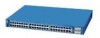
Link present. Link fault. Note After a port is using less than 50 percent of its total capacity, and so on the Catalyst 3508, 3512, 3524, and 3548 XL Switches Port Mode STATUS (port status) UTL (utilization) DUPLEX LED Color Off Solid green Flashing green Alternating green-amber Solid amber Green ...Off Green Meaning No link. If the right-most LED is amber, the switch is using 50 percent or more of LED Colors...
Link present. Link fault. Note After a port is using less than 50 percent of its total capacity, and so on the Catalyst 3508, 3512, 3524, and 3548 XL Switches Port Mode STATUS (port status) UTL (utilization) DUPLEX LED Color Off Solid green Flashing green Alternating green-amber Solid amber Green ...Off Green Meaning No link. If the right-most LED is amber, the switch is using 50 percent or more of LED Colors...
Installation Guide
Page 42
...operating in half duplex. Port is operating in full duplex. 1-18 Catalyst 3500 Series XL Hardware Installation Guide 78-6456-04 Table 1-8 Meaning of LED Colors in Different Modes on the Catalyst 3524-PWR XL Switch Port Mode STATUS (port status) DUPLEX LED Color Off Solid green ...possible loops. Activity. Front-Panel Description Chapter 1 Product Overview Table 1-7 Meaning of LED Colors in Different Modes on the Catalyst 3508, 3512, 3524, and 3548 XL Switches (continued) Port Mode SPEED (speed) LED Color 10/100 ports Off Green 1000BaseX ports Off Green Meaning Port is ...
...operating in half duplex. Port is operating in full duplex. 1-18 Catalyst 3500 Series XL Hardware Installation Guide 78-6456-04 Table 1-8 Meaning of LED Colors in Different Modes on the Catalyst 3524-PWR XL Switch Port Mode STATUS (port status) DUPLEX LED Color Off Solid green ...possible loops. Activity. Front-Panel Description Chapter 1 Product Overview Table 1-7 Meaning of LED Colors in Different Modes on the Catalyst 3508, 3512, 3524, and 3548 XL Switches (continued) Port Mode SPEED (speed) LED Color 10/100 ports Off Green 1000BaseX ports Off Green Meaning Port is ...
Installation Guide
Page 44
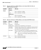
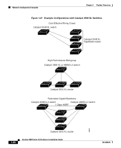
... 12X 13 14 15 16 13X 17 18 19 20 21 22 23 24 15X 14X 16X < 25% + 25% - 49% + 50% + Catalyst 3500 XL 1 2 Figure 1-16 Bandwidth Utilization for the Catalyst 3548 XL Switch 28366 SYSTEM RPS STATUS UTIL DUPLX SPEED MODE 12 1X 3 24 56 78 9 10 11 12 13 14 15 16 15X 17... green and if both the GBIC LEDs are green and the lower GBIC LED is amber, the switch is using less than 25 percent of its total capacity, and so on the Catalyst 3548 XL switch are green, the switch is using between 25 and 50 percent of its total bandwidth. If all 10/100 port...
... 12X 13 14 15 16 13X 17 18 19 20 21 22 23 24 15X 14X 16X < 25% + 25% - 49% + 50% + Catalyst 3500 XL 1 2 Figure 1-16 Bandwidth Utilization for the Catalyst 3548 XL Switch 28366 SYSTEM RPS STATUS UTIL DUPLX SPEED MODE 12 1X 3 24 56 78 9 10 11 12 13 14 15 16 15X 17... green and if both the GBIC LEDs are green and the lower GBIC LED is amber, the switch is using less than 25 percent of its total capacity, and so on the Catalyst 3548 XL switch are green, the switch is using between 25 and 50 percent of its total bandwidth. If all 10/100 port...

Installation Guide
Page 46
... SUPPLY SPECIFIED IN MANUAL. -48V @3A, +12V @6A CONSOLE AC power connector Redundant power system connector RJ-45 console port Figure 1-20 Catalyst 3548 XL Rear Panel Chapter 1 Product Overview Fans 30293 28012 RATING 100-127/200-240V~ 1.6A/0.9A 50-60HZ DC INPUTS FOR REMOTE POWER SUPPLY SPECIFIED... @1.1A CONSOLE AC power connector Fan exhaust RJ-45 console port Redundant power system connector Power Connectors You can provide power to the switch either through the internal power supply or through the Cisco RPS. 1-22 Catalyst 3500 Series XL Hardware Installation Guide 78-6456-04
... SUPPLY SPECIFIED IN MANUAL. -48V @3A, +12V @6A CONSOLE AC power connector Redundant power system connector RJ-45 console port Figure 1-20 Catalyst 3548 XL Rear Panel Chapter 1 Product Overview Fans 30293 28012 RATING 100-127/200-240V~ 1.6A/0.9A 50-60HZ DC INPUTS FOR REMOTE POWER SUPPLY SPECIFIED... @1.1A CONSOLE AC power connector Fan exhaust RJ-45 console port Redundant power system connector Power Connectors You can provide power to the switch either through the internal power supply or through the Cisco RPS. 1-22 Catalyst 3500 Series XL Hardware Installation Guide 78-6456-04

Installation Guide
Page 47
... for four external devices that supports input voltages between 100 and 240 VAC. The switches do not support the fully-redundant configuration described in the RPS documentation. For more information on the Catalyst 3508, 3512, 3524, and 3548 XL Switches The Cisco RPS 600 (model PWR600-AC-RPS) provides a quasi-redundant power source for each external...
... for four external devices that supports input voltages between 100 and 240 VAC. The switches do not support the fully-redundant configuration described in the RPS documentation. For more information on the Catalyst 3508, 3512, 3524, and 3548 XL Switches The Cisco RPS 600 (model PWR600-AC-RPS) provides a quasi-redundant power source for each external...

Installation Guide
Page 50
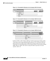
... during congestion and to help control both delay and jitter within the network. When you use a stack of Catalyst 3548 XL switches, you can create backup paths between the switch and its connected servers and routers. • An evolving demand for IP telephony • Use quality of... links or Fast EtherChannel or Gigabit EtherChannel links. You can connect up to nine Catalyst 3500 XL switches through GigaStack GBIC connections. To preserve connectivity between the switches in case one switch in the same logical network as the users who access those resources most. •...
... during congestion and to help control both delay and jitter within the network. When you use a stack of Catalyst 3548 XL switches, you can create backup paths between the switch and its connected servers and routers. • An evolving demand for IP telephony • Use quality of... links or Fast EtherChannel or Gigabit EtherChannel links. You can connect up to nine Catalyst 3500 XL switches through GigaStack GBIC connections. To preserve connectivity between the switches in case one switch in the same logical network as the users who access those resources most. •...
Installation Guide
Page 52
Network Configuration Examples Chapter 1 Product Overview Figure 1-21 Example Configurations with Catalyst 3500 XL Switches Cost-Effective Wiring Closet Catalyst 3548 XL switch Catalyst 3548 XL GigaStack cluster High-Performance Workgroup Catalyst 3508 XL or 4908G-L3 switch Catalyst 3500 XL cluster Redundant Gigabit Backbone Catalyst 4908G-L3 switch Catalyst 4908G-L3 switch 1 Gbps HSRP 33090 Catalyst 3500 XL cluster 1-28 Catalyst 3500 Series XL Hardware Installation Guide 78-6456-04
Network Configuration Examples Chapter 1 Product Overview Figure 1-21 Example Configurations with Catalyst 3500 XL Switches Cost-Effective Wiring Closet Catalyst 3548 XL switch Catalyst 3548 XL GigaStack cluster High-Performance Workgroup Catalyst 3508 XL or 4908G-L3 switch Catalyst 3500 XL cluster Redundant Gigabit Backbone Catalyst 4908G-L3 switch Catalyst 4908G-L3 switch 1 Gbps HSRP 33090 Catalyst 3500 XL cluster 1-28 Catalyst 3500 Series XL Hardware Installation Guide 78-6456-04
Installation Guide
Page 62
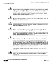
... if interconnections are made by using uninsulated exposed metal contacts, conductors, or terminals. Statement 1072 The following warning applies to the Catalyst 3508, 3512, 3524, and 3548 XL switches: Warning Attach only the Cisco RPS (model PWR600-AC-RPS) to all power is connected. To ensure that all national laws and regulations. Statement 140 Warning...
... if interconnections are made by using uninsulated exposed metal contacts, conductors, or terminals. Statement 1072 The following warning applies to the Catalyst 3508, 3512, 3524, and 3548 XL switches: Warning Attach only the Cisco RPS (model PWR600-AC-RPS) to all power is connected. To ensure that all national laws and regulations. Statement 140 Warning...
Installation Guide
Page 68
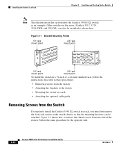
... a 19-inch or a 24-inch standard rack, follow the instructions described in these procedures: • Removing screws from the switch • Attaching the brackets to install the Catalyst 3548 XL switch in a rack, you must first remove the front side screws in a rack • Attaching the optional cable guide Removing Screws from one side of...
... a 19-inch or a 24-inch standard rack, follow the instructions described in these procedures: • Removing screws from the switch • Attaching the brackets to install the Catalyst 3548 XL switch in a rack, you must first remove the front side screws in a rack • Attaching the optional cable guide Removing Screws from one side of...
Installation Guide
Page 69
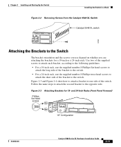
... 24-inch rack. Chapter 2 Installing and Starting Up the Switch Installing the Switch in a Rack Figure 2-2 Removing Screws from the Catalyst 3548 XL Switch 46 47 48 47X 1 2 48X Catalyst 3548 XL switch 30062 Attaching the Brackets to the switch. Follow the same steps to attach the second bracket to one... side of the bracket to the Switch The bracket orientation and the ...
... 24-inch rack. Chapter 2 Installing and Starting Up the Switch Installing the Switch in a Rack Figure 2-2 Removing Screws from the Catalyst 3548 XL Switch 46 47 48 47X 1 2 48X Catalyst 3548 XL switch 30062 Attaching the Brackets to the switch. Follow the same steps to attach the second bracket to one... side of the bracket to the Switch The bracket orientation and the ...
Installation Guide
Page 72
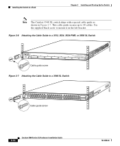
...SPEED 2X MODE 16X 18X 32X 34X 48X 2 Cable guide screw 28324 2-14 Catalyst 3500 Series XL Hardware Installation Guide 78-6456-04 Figure 2-6 Attaching the Cable Guide to a 3512, 3524, 3524-PWR, or 3508 XL Switch 1 MODE SYSTEM RPS 2 3 4 5 STATUS UTIL DUPLX SPEED 6 7 ...Cable guide screw Figure 2-7 Attaching the Cable Guide to mount it on the left bracket. 22441 Installing the Switch in a Rack Chapter 2 Installing and Starting Up the Switch Note The Catalyst 3548 XL switch ships with a special cable guide as shown in Figure 2-7. This cable guide secures up to 48 cables....
...SPEED 2X MODE 16X 18X 32X 34X 48X 2 Cable guide screw 28324 2-14 Catalyst 3500 Series XL Hardware Installation Guide 78-6456-04 Figure 2-6 Attaching the Cable Guide to a 3512, 3524, 3524-PWR, or 3508 XL Switch 1 MODE SYSTEM RPS 2 3 4 5 STATUS UTIL DUPLX SPEED 6 7 ...Cable guide screw Figure 2-7 Attaching the Cable Guide to mount it on the left bracket. 22441 Installing the Switch in a Rack Chapter 2 Installing and Starting Up the Switch Note The Catalyst 3548 XL switch ships with a special cable guide as shown in Figure 2-7. This cable guide secures up to 48 cables....

Installation Guide
Page 98
Appendix A Technical Specifications Table A-2 Technical Specifications for the Catalyst 3512, 3524, and 3548 XL Switches Catalyst 3512 XL Catalyst 3524 XL Catalyst 3548 XL Environmental Ranges Operating temperature 32 to 113°F (0 to 45°C) 32 to 113°F (0 to 45°C) 32 to 113°F (0 to 45°C) ....82 x 17.5 in. 1.73 x 15.34 x 17.5 in D x W) (4.45 x 30.02 x 44.45 cm) (4.45 x 30.02 x 44.45 cm) (4.39 x 39.0 x 44.45 cm) Catalyst 3500 Series XL Hardware Installation Guide A-2 78-6456-04
Appendix A Technical Specifications Table A-2 Technical Specifications for the Catalyst 3512, 3524, and 3548 XL Switches Catalyst 3512 XL Catalyst 3524 XL Catalyst 3548 XL Environmental Ranges Operating temperature 32 to 113°F (0 to 45°C) 32 to 113°F (0 to 45°C) 32 to 113°F (0 to 45°C) ....82 x 17.5 in. 1.73 x 15.34 x 17.5 in D x W) (4.45 x 30.02 x 44.45 cm) (4.45 x 30.02 x 44.45 cm) (4.39 x 39.0 x 44.45 cm) Catalyst 3500 Series XL Hardware Installation Guide A-2 78-6456-04
Installation Guide
Page 110
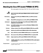
...) angeschlossen werden. Catalyst 3500 Series XL Hardware Installation Guide C-2 78-6456-04 Attaching the Cisco RPS (model PWR600-AC-RPS) Appendix C Translated Safety Warnings Attaching the Cisco RPS (model PWR600-AC-RPS) This warning applies to the RPS receptacle. Warning Attach only the Cisco RPS (model PWR600-AC-RPS) to the Catalyst 3508, 3512, 3524, and 3548 XL switches.
...) angeschlossen werden. Catalyst 3500 Series XL Hardware Installation Guide C-2 78-6456-04 Attaching the Cisco RPS (model PWR600-AC-RPS) Appendix C Translated Safety Warnings Attaching the Cisco RPS (model PWR600-AC-RPS) This warning applies to the RPS receptacle. Warning Attach only the Cisco RPS (model PWR600-AC-RPS) to the Catalyst 3508, 3512, 3524, and 3548 XL switches.


