
Installation Guide
Page 28
... - 1000BaseSX GBIC module - 1000BaseLX/LH GBIC module - 1000BaseZX GBIC module Catalyst 3500 Series XL Hardware Installation Guide 1-4 78-6456-04 Features Chapter 1 Product Overview Table 1-2 Catalyst 3512, 3524, 3524-PWR, and 3548 XL Features Feature Performance and Configuration Description • Autonegotiation of speed and duplex... 802.1Q trunking support on all ports • Support for voice VLAN ID (VVID) • High-speed EtherChannel connections between switches and servers • 8192 MAC addresses • IEEE 802.1p capable • CGMP to limit the flooding of IP multicast...
... - 1000BaseSX GBIC module - 1000BaseLX/LH GBIC module - 1000BaseZX GBIC module Catalyst 3500 Series XL Hardware Installation Guide 1-4 78-6456-04 Features Chapter 1 Product Overview Table 1-2 Catalyst 3512, 3524, 3524-PWR, and 3548 XL Features Feature Performance and Configuration Description • Autonegotiation of speed and duplex... 802.1Q trunking support on all ports • Support for voice VLAN ID (VVID) • High-speed EtherChannel connections between switches and servers • 8192 MAC addresses • IEEE 802.1p capable • CGMP to limit the flooding of IP multicast...

Installation Guide
Page 29
... panel of inline phone power on a per-port basis on AC input and supplies DC output to the Catalyst 3512, 3524, and 3548 XL switches • Connection for optional Cisco RPS 600 that operates on all 24 10/100 Ethernet ports • Auto-detection and control of the...module slots. All Catalyst 3500 XL switches have a set of LEDs and a Mode button. (The Catalyst 3548 XL switch has a Mode label that operates on AC input and supplies DC output to the Catalyst 3524-PWR XL switch Inline Power (Catalyst 3524-PWR XL switch only) • Ability to provide inline power for Cisco IP Phones from...
... panel of inline phone power on a per-port basis on AC input and supplies DC output to the Catalyst 3512, 3524, and 3548 XL switches • Connection for optional Cisco RPS 600 that operates on all 24 10/100 Ethernet ports • Auto-detection and control of the...module slots. All Catalyst 3500 XL switches have a set of LEDs and a Mode button. (The Catalyst 3548 XL switch has a Mode label that operates on AC input and supplies DC output to the Catalyst 3524-PWR XL switch Inline Power (Catalyst 3524-PWR XL switch only) • Ability to provide inline power for Cisco IP Phones from...

Installation Guide
Page 31
... 12 11X 12X 13 14 13X 15 16 17 18 19 20 21 22 23 24 23X 14X 24X 10/100 inline-power ports Figure 1-6 Catalyst 3548 XL Switch 1 2 GBIC module slots 28010 SYSTEM RPS 12 1X 34 56 78 9 10 11 12 13 14 15 16 15X 17 18 17X 19 20 21... Figure 1-6, ports 1 and 2 are grouped in pairs. The first member of 100 meters, to any compatible network device: • 10BaseT-compatible devices such as workstations, Cisco IP Phones, and hubs through standard RJ-45 connectors and Category 3, 4, or 5 cabling 78-6456-04 Catalyst 3500 Series XL Hardware Installation Guide 1-7
... 12 11X 12X 13 14 13X 15 16 17 18 19 20 21 22 23 24 23X 14X 24X 10/100 inline-power ports Figure 1-6 Catalyst 3548 XL Switch 1 2 GBIC module slots 28010 SYSTEM RPS 12 1X 34 56 78 9 10 11 12 13 14 15 16 15X 17 18 17X 19 20 21... Figure 1-6, ports 1 and 2 are grouped in pairs. The first member of 100 meters, to any compatible network device: • 10BaseT-compatible devices such as workstations, Cisco IP Phones, and hubs through standard RJ-45 connectors and Category 3, 4, or 5 cabling 78-6456-04 Catalyst 3500 Series XL Hardware Installation Guide 1-7

Installation Guide
Page 32
... devices support and full-duplex transmission, if the attached device supports it) and configures itself accordingly. Pinouts for Cisco IP Phones. The Catalyst 3548 and 3524-PWR XL switches also support per -port basis, you select the Auto setting for ports operating at 10 Mbps can : •...cables do not work for inline power on the Catalyst 3512, 3524, and 3548 XL switches-must be set for autonegotiation, the port can control whether or not a Catalyst 3524-PWR XL 10/100 port automatically provides power when a Cisco IP Phone is required for 100BaseTX traffic. Ports operating...
... devices support and full-duplex transmission, if the attached device supports it) and configures itself accordingly. Pinouts for Cisco IP Phones. The Catalyst 3548 and 3524-PWR XL switches also support per -port basis, you select the Auto setting for ports operating at 10 Mbps can : •...cables do not work for inline power on the Catalyst 3512, 3524, and 3548 XL switches-must be set for autonegotiation, the port can control whether or not a Catalyst 3524-PWR XL 10/100 port automatically provides power when a Cisco IP Phone is required for 100BaseTX traffic. Ports operating...

Installation Guide
Page 33
...Cisco IP Phones, refer to the documentation that came with the switch. The GigaStack GBIC supports one full-duplex link (in a point-to-point configuration) or up to eight GBICs in the Catalyst 3508G XL switch. You can install up to two GBICs in the Catalyst 3512, 3524, 3524-PWR and 3548 XL switches... documentation that came with your Cisco IP Phone. However, when you can connect the Cisco IP Phone to a Catalyst 3524-PWR XL 10/100 port and to nine Catalyst 3500 XL switches. You also can order GBIC modules separately. GBIC Module Slots The Cisco Gigabit Interface Converter (GBIC) ...
...Cisco IP Phones, refer to the documentation that came with the switch. The GigaStack GBIC supports one full-duplex link (in a point-to-point configuration) or up to eight GBICs in the Catalyst 3508G XL switch. You can install up to two GBICs in the Catalyst 3512, 3524, 3524-PWR and 3548 XL switches... documentation that came with your Cisco IP Phone. However, when you can connect the Cisco IP Phone to a Catalyst 3524-PWR XL 10/100 port and to nine Catalyst 3500 XL switches. You also can order GBIC modules separately. GBIC Module Slots The Cisco Gigabit Interface Converter (GBIC) ...

Installation Guide
Page 38
... System Status System is operating normally. For information on the System LED colors during POST, see the "Powering On the Switch and Running POST" section on . Front-Panel Description Figure 1-12 Catalyst 3548 XL LEDs Port LEDs Chapter 1 Product Overview SYSTEM RPS STATUS UTIL DUPLX SPEED MODE 1 1X 23 45 67 8 9 10 11... LED The System LED shows whether the system is receiving power and is not functioning properly. System is not powered on page 2-17. 1-14 Catalyst 3500 Series XL Hardware Installation Guide 78-6456-04 Table 1-3 lists the LED colors and their meanings.
... System Status System is operating normally. For information on the System LED colors during POST, see the "Powering On the Switch and Running POST" section on . Front-Panel Description Figure 1-12 Catalyst 3548 XL LEDs Port LEDs Chapter 1 Product Overview SYSTEM RPS STATUS UTIL DUPLX SPEED MODE 1 1X 23 45 67 8 9 10 11... LED The System LED shows whether the system is receiving power and is not functioning properly. System is not powered on page 2-17. 1-14 Catalyst 3500 Series XL Hardware Installation Guide 78-6456-04 Table 1-3 lists the LED colors and their meanings.

Installation Guide
Page 39
... down , or a fan on . Note The Cisco RPS 300 (model PWR300-AC-RPS) supports the Catalyst 3524-PWR XL switch. 78-6456-04 Catalyst 3500 Series XL Hardware Installation Guide 1-15 Note The Cisco RPS 600 (model PWR600-AC-RPS) supports the Catalyst 3512, 3524, 3548, and 3508 XL switches. RPS and the switch AC power supply are using power from the...
... down , or a fan on . Note The Cisco RPS 300 (model PWR300-AC-RPS) supports the Catalyst 3524-PWR XL switch. 78-6456-04 Catalyst 3500 Series XL Hardware Installation Guide 1-15 Note The Cisco RPS 600 (model PWR600-AC-RPS) supports the Catalyst 3512, 3524, 3548, and 3508 XL switches. RPS and the switch AC power supply are using power from the...

Installation Guide
Page 40
...is the default mode. One of information displayed through the port LEDs. The port modes (Table 1-6) determine the type of the power supplies in the Catalyst 3548 XL switch, press the Mode label. The current bandwidth in the stack. Port LEDs and Modes Each 10/100 port and module slot has a port LED.... For more information about the individual ports. To select or change port modes, the meaning of the switch is down , or a fan on the RPS could have failed. RPS is operating on the Cisco RPS 300, refer to interpret the port LED colors after you change a mode, press the Mode ...
...is the default mode. One of information displayed through the port LEDs. The port modes (Table 1-6) determine the type of the power supplies in the Catalyst 3548 XL switch, press the Mode label. The current bandwidth in the stack. Port LEDs and Modes Each 10/100 port and module slot has a port LED.... For more information about the individual ports. To select or change port modes, the meaning of the switch is down , or a fan on the RPS could have failed. RPS is operating on the Cisco RPS 300, refer to interpret the port LED colors after you change a mode, press the Mode ...

Installation Guide
Page 41
... Description The port duplex mode: full duplex or half duplex. Table 1-7 Meaning of its total capacity, and so on the Catalyst 3508, 3512, 3524, and 3548 XL Switches Port Mode STATUS (port status) UTL (utilization) DUPLEX LED Color Off Solid green Flashing green Alternating green-amber Solid amber Green...is using less than 50 percent of its total bandwidth. If the right-most LED is amber, the switch is operating in full duplex. 78-6456-04 Catalyst 3500 Series XL Hardware Installation Guide 1-17 Port was disabled by management or an address violation or was blocked by Spanning...
... Description The port duplex mode: full duplex or half duplex. Table 1-7 Meaning of its total capacity, and so on the Catalyst 3508, 3512, 3524, and 3548 XL Switches Port Mode STATUS (port status) UTL (utilization) DUPLEX LED Color Off Solid green Flashing green Alternating green-amber Solid amber Green...is using less than 50 percent of its total bandwidth. If the right-most LED is amber, the switch is operating in full duplex. 78-6456-04 Catalyst 3500 Series XL Hardware Installation Guide 1-17 Port was disabled by management or an address violation or was blocked by Spanning...
Installation Guide
Page 42
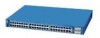
... Product Overview Table 1-7 Meaning of LED Colors in full duplex. 1-18 Catalyst 3500 Series XL Hardware Installation Guide 78-6456-04 Port is operating in Different Modes on the Catalyst 3508, 3512, 3524, and 3548 XL Switches (continued) Port Mode SPEED (speed) LED Color 10/100 ports Off Green...and alignment and jabber errors are monitored for possible loops. Table 1-8 Meaning of LED Colors in Different Modes on the Catalyst 3524-PWR XL Switch Port Mode STATUS (port status) DUPLEX LED Color Off Solid green Flashing green Alternating green-amber Solid amber Off Green Meaning...
... Product Overview Table 1-7 Meaning of LED Colors in full duplex. 1-18 Catalyst 3500 Series XL Hardware Installation Guide 78-6456-04 Port is operating in Different Modes on the Catalyst 3508, 3512, 3524, and 3548 XL Switches (continued) Port Mode SPEED (speed) LED Color 10/100 ports Off Green...and alignment and jabber errors are monitored for possible loops. Table 1-8 Meaning of LED Colors in Different Modes on the Catalyst 3524-PWR XL Switch Port Mode STATUS (port status) DUPLEX LED Color Off Solid green Flashing green Alternating green-amber Solid amber Off Green Meaning...
Installation Guide
Page 44
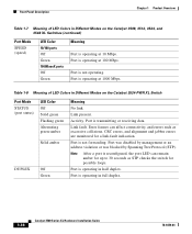
... port LEDs are green and if both the GBIC LEDs are amber, the switch is using less than 25 percent of its total capacity, and so on the Catalyst 3548 XL switch are green and the lower GBIC LED is amber, the switch is using between 25 and 50 percent of its total bandwidth. Front-Panel... 12X 13 14 15 16 13X 17 18 19 20 21 22 23 24 15X 14X 16X < 25% + 25% - 49% + 50% + Catalyst 3500 XL 1 2 Figure 1-16 Bandwidth Utilization for the Catalyst 3548 XL Switch 28366 SYSTEM RPS STATUS UTIL DUPLX SPEED MODE 12 1X 3 24 56 78 9 10 11 12 13 14 15 16 15X 17...
... port LEDs are green and if both the GBIC LEDs are amber, the switch is using less than 25 percent of its total capacity, and so on the Catalyst 3548 XL switch are green and the lower GBIC LED is amber, the switch is using between 25 and 50 percent of its total bandwidth. Front-Panel... 12X 13 14 15 16 13X 17 18 19 20 21 22 23 24 15X 14X 16X < 25% + 25% - 49% + 50% + Catalyst 3500 XL 1 2 Figure 1-16 Bandwidth Utilization for the Catalyst 3548 XL Switch 28366 SYSTEM RPS STATUS UTIL DUPLX SPEED MODE 12 1X 3 24 56 78 9 10 11 12 13 14 15 16 15X 17...

Installation Guide
Page 47
... and one connector at each external device. Note Do not connect the switch power cord to an AC outlet if the switch is also connected to a powered-on the Catalyst 3508, 3512, 3524, and 3548 XL Switches The Cisco RPS 600 (model PWR600-AC-RPS) provides a quasi-redundant power source for each cable ...end) to connect four external devices to the four DC output power modules. The AC input to the Cisco RPS is fully redundant, but...
... and one connector at each external device. Note Do not connect the switch power cord to an AC outlet if the switch is also connected to a powered-on the Catalyst 3508, 3512, 3524, and 3548 XL Switches The Cisco RPS 600 (model PWR600-AC-RPS) provides a quasi-redundant power source for each cable ...end) to connect four external devices to the four DC output power modules. The AC input to the Cisco RPS is fully redundant, but...

Installation Guide
Page 50
... Ethernet segment. • Use the Fast EtherChannel or Gigabit EtherChannel feature between the switch and its connected workstations. • The increased power of Catalyst 3548 XL switches, you can connect the switch to other devices and create backup paths by using the Catalyst 3500 XL switches to create the following: • Cost-effective wiring closet-A cost-effective way to...
... Ethernet segment. • Use the Fast EtherChannel or Gigabit EtherChannel feature between the switch and its connected workstations. • The increased power of Catalyst 3548 XL switches, you can connect the switch to other devices and create backup paths by using the Catalyst 3500 XL switches to create the following: • Cost-effective wiring closet-A cost-effective way to...
Installation Guide
Page 52
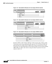
Network Configuration Examples Chapter 1 Product Overview Figure 1-21 Example Configurations with Catalyst 3500 XL Switches Cost-Effective Wiring Closet Catalyst 3548 XL switch Catalyst 3548 XL GigaStack cluster High-Performance Workgroup Catalyst 3508 XL or 4908G-L3 switch Catalyst 3500 XL cluster Redundant Gigabit Backbone Catalyst 4908G-L3 switch Catalyst 4908G-L3 switch 1 Gbps HSRP 33090 Catalyst 3500 XL cluster 1-28 Catalyst 3500 Series XL Hardware Installation Guide 78-6456-04
Network Configuration Examples Chapter 1 Product Overview Figure 1-21 Example Configurations with Catalyst 3500 XL Switches Cost-Effective Wiring Closet Catalyst 3548 XL switch Catalyst 3548 XL GigaStack cluster High-Performance Workgroup Catalyst 3508 XL or 4908G-L3 switch Catalyst 3500 XL cluster Redundant Gigabit Backbone Catalyst 4908G-L3 switch Catalyst 4908G-L3 switch 1 Gbps HSRP 33090 Catalyst 3500 XL cluster 1-28 Catalyst 3500 Series XL Hardware Installation Guide 78-6456-04
Installation Guide
Page 62
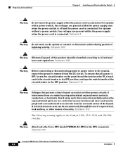
... work on the panel board that services the DC circuit, switch the circuit breaker to the RPS receptacle. Statement 1072 The following warning applies to the Catalyst 3508, 3512, 3524, and 3548 XL switches: Warning Attach only the Cisco RPS (model PWR600-AC-RPS) to the OFF position,... and tape the switch handle of lightning activity. To ensure that all national laws and ...
... work on the panel board that services the DC circuit, switch the circuit breaker to the RPS receptacle. Statement 1072 The following warning applies to the Catalyst 3508, 3512, 3524, and 3548 XL switches: Warning Attach only the Cisco RPS (model PWR600-AC-RPS) to the OFF position,... and tape the switch handle of lightning activity. To ensure that all national laws and ...
Installation Guide
Page 68
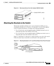
... instructions described in these procedures: • Removing screws from the switch • Attaching the brackets to install the Catalyst 3548 XL switch in a rack, you plan to the switch • Mounting the switch in the series (Catalyst 3512, 3524, 3524-PWR, and 3548 XL) can be installed as an example. Other switches in a rack • Attaching the optional cable guide Removing...
... instructions described in these procedures: • Removing screws from the switch • Attaching the brackets to install the Catalyst 3548 XL switch in a rack, you plan to the switch • Mounting the switch in the series (Catalyst 3512, 3524, 3524-PWR, and 3548 XL) can be installed as an example. Other switches in a rack • Attaching the optional cable guide Removing...
Installation Guide
Page 69
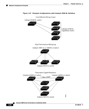
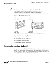
... and Starting Up the Switch Installing the Switch in a Rack Figure 2-2 Removing Screws from the Catalyst 3548 XL Switch 46 47 48 47X 1 2 48X Catalyst 3548 XL switch 30062 Attaching the Brackets to the Switch The bracket orientation and the screws you use the supplied number-8 Phillips truss-head screws to attach the short side of the switch. Follow the same steps...
... and Starting Up the Switch Installing the Switch in a Rack Figure 2-2 Removing Screws from the Catalyst 3548 XL Switch 46 47 48 47X 1 2 48X Catalyst 3548 XL switch 30062 Attaching the Brackets to the Switch The bracket orientation and the screws you use the supplied number-8 Phillips truss-head screws to attach the short side of the switch. Follow the same steps...
Installation Guide
Page 72
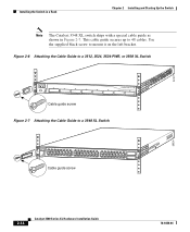
... 4 5 STATUS UTIL DUPLX SPEED 6 7 8 Cable guide screw Figure 2-7 Attaching the Cable Guide to 48 cables. This cable guide secures up to a 3548 XL Switch SYSTEM RPS 12 1X 34 56 78 9 10 11 12 13 14 15 16 15X 17 18 17X 19 20 21 22 23 24 25 ...34X 48X 2 Cable guide screw 28324 2-14 Catalyst 3500 Series XL Hardware Installation Guide 78-6456-04 Use the supplied black screw to mount it on the left bracket. 22441 Installing the Switch in a Rack Chapter 2 Installing and Starting Up the Switch Note The Catalyst 3548 XL switch ships with a special cable guide as shown...
... 4 5 STATUS UTIL DUPLX SPEED 6 7 8 Cable guide screw Figure 2-7 Attaching the Cable Guide to 48 cables. This cable guide secures up to a 3548 XL Switch SYSTEM RPS 12 1X 34 56 78 9 10 11 12 13 14 15 16 15X 17 18 17X 19 20 21 22 23 24 25 ...34X 48X 2 Cable guide screw 28324 2-14 Catalyst 3500 Series XL Hardware Installation Guide 78-6456-04 Use the supplied black screw to mount it on the left bracket. 22441 Installing the Switch in a Rack Chapter 2 Installing and Starting Up the Switch Note The Catalyst 3548 XL switch ships with a special cable guide as shown...

Installation Guide
Page 98
Appendix A Technical Specifications Table A-2 Technical Specifications for the Catalyst 3512, 3524, and 3548 XL Switches Catalyst 3512 XL Catalyst 3524 XL Catalyst 3548 XL Environmental Ranges Operating temperature 32 to 113°F (0 to 45°C) 32 to 113°F (0 to 45°C) 32 to 113°F (0 to 45°C) ....82 x 17.5 in. 1.73 x 15.34 x 17.5 in D x W) (4.45 x 30.02 x 44.45 cm) (4.45 x 30.02 x 44.45 cm) (4.39 x 39.0 x 44.45 cm) Catalyst 3500 Series XL Hardware Installation Guide A-2 78-6456-04
Appendix A Technical Specifications Table A-2 Technical Specifications for the Catalyst 3512, 3524, and 3548 XL Switches Catalyst 3512 XL Catalyst 3524 XL Catalyst 3548 XL Environmental Ranges Operating temperature 32 to 113°F (0 to 45°C) 32 to 113°F (0 to 45°C) 32 to 113°F (0 to 45°C) ....82 x 17.5 in. 1.73 x 15.34 x 17.5 in D x W) (4.45 x 30.02 x 44.45 cm) (4.45 x 30.02 x 44.45 cm) (4.39 x 39.0 x 44.45 cm) Catalyst 3500 Series XL Hardware Installation Guide A-2 78-6456-04
Installation Guide
Page 110
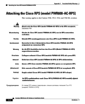
... ao receptáculo RPS. ¡Advertencia! Warning Attach only the Cisco RPS (model PWR600-AC-RPS) to the Catalyst 3508, 3512, 3524, and 3548 XL switches. Avvertenza Collegare soltanto il Cisco RPS (modello PWR600-AC-RPS) alla presa RPS. Advarsel! Varning! Sólo conecte el Cisco RPS (modelo PWR600-AC-RPS) al receptáculo RPS...
... ao receptáculo RPS. ¡Advertencia! Warning Attach only the Cisco RPS (model PWR600-AC-RPS) to the Catalyst 3508, 3512, 3524, and 3548 XL switches. Avvertenza Collegare soltanto il Cisco RPS (modello PWR600-AC-RPS) alla presa RPS. Advarsel! Varning! Sólo conecte el Cisco RPS (modelo PWR600-AC-RPS) al receptáculo RPS...


