

Hardware Installation Guide
Page 19
.../aag_c07_563807.pdf for data only. 2. Only 1 EHWIC Gigabit Ethernet Switch can be installed in slot 0 (Right). Figure 1-3 shows the front panel of the Cisco 1905 and Cisco 1921 with antennas mounted. OL-19084-02 Cisco 1900 Series Hardware Installation 1-3 Figure 1-2 shows the back panel of a Cisco 1941 wireless router with ports and LEDs. Only slot...
.../aag_c07_563807.pdf for data only. 2. Only 1 EHWIC Gigabit Ethernet Switch can be installed in slot 0 (Right). Figure 1-3 shows the front panel of the Cisco 1905 and Cisco 1921 with antennas mounted. OL-19084-02 Cisco 1900 Series Hardware Installation 1-3 Figure 1-2 shows the back panel of a Cisco 1941 wireless router with ports and LEDs. Only slot...

Hardware Installation Guide
Page 21
.../ps10538/aag_c07_563807.pdf for data only. 2. See Module Support on the left side of the Cisco 1941 and Cisco 1941W Router 17 18 19 20 21 22 EHWIC 1 DO NOT REMOVE DURING NETWORKING OPERATION CF 1 Cisco 1900 Series EHWIC 0 DO NOT REMOVE DURING CF 0 ISM/WLAN EN NETWORKING OPERATION AUX S... 12 CompactFlash 0 13 HWIC slot 1 (EHWIC, HWIC, or WIC)-double wide4 15 CompactFlash 1 14 CF 1 16 KensingtonTM security slot 17 On/Off switch 18 Input power connection 19 AUX port 20 S (Speed) 21 GE 0/0 22 L (Link) 1. Chapter 1 Overview of the Router Hardware Features Figure ...
.../ps10538/aag_c07_563807.pdf for data only. 2. See Module Support on the left side of the Cisco 1941 and Cisco 1941W Router 17 18 19 20 21 22 EHWIC 1 DO NOT REMOVE DURING NETWORKING OPERATION CF 1 Cisco 1900 Series EHWIC 0 DO NOT REMOVE DURING CF 0 ISM/WLAN EN NETWORKING OPERATION AUX S... 12 CompactFlash 0 13 HWIC slot 1 (EHWIC, HWIC, or WIC)-double wide4 15 CompactFlash 1 14 CF 1 16 KensingtonTM security slot 17 On/Off switch 18 Input power connection 19 AUX port 20 S (Speed) 21 GE 0/0 22 L (Link) 1. Chapter 1 Overview of the Router Hardware Features Figure ...

Hardware Installation Guide
Page 24
... memory and enhanced high-speed WAN interface cards (EHWICs) fit into connectors inside. Table 1-2 summarizes the optional modules: Cisco 1900 Series Hardware Installation 1-8 OL-19084-02 The USB port provides connection for PoE. (See Figure 1-2.) • ...There are backward compatible with USB1.1 devices. One console port (RJ-45 connector). The Cisco 1905, and Cisco 1921 have a USB 5-pin mini Type-B port. They can be installed either by inserting them into slots .... Simply follow the installation prompts to optional integrated switch modules.
... memory and enhanced high-speed WAN interface cards (EHWICs) fit into connectors inside. Table 1-2 summarizes the optional modules: Cisco 1900 Series Hardware Installation 1-8 OL-19084-02 The USB port provides connection for PoE. (See Figure 1-2.) • ...There are backward compatible with USB1.1 devices. One console port (RJ-45 connector). The Cisco 1905, and Cisco 1921 have a USB 5-pin mini Type-B port. They can be installed either by inserting them into slots .... Simply follow the installation prompts to optional integrated switch modules.

Hardware Installation Guide
Page 36
Do not operate the system unless all power before doing the following: - Statement 1046 • Locate the emergency power-off switch in the room in which you can quickly turn off the power. • Disconnect all cards, faceplates, front covers, and rear covers.... • Do not work on the system or connect or disconnect cables during periods of this product should be made first and disconnected last. Cisco 1900 Series Hardware Installation 2-2 OL-19084-02 Safety Recommendations Chapter 2 Preparing for possible hazards in place. Working near power supplies - Statement 1004 Warning...
Do not operate the system unless all power before doing the following: - Statement 1046 • Locate the emergency power-off switch in the room in which you can quickly turn off the power. • Disconnect all cards, faceplates, front covers, and rear covers.... • Do not work on the system or connect or disconnect cables during periods of this product should be made first and disconnected last. Cisco 1900 Series Hardware Installation 2-2 OL-19084-02 Safety Recommendations Chapter 2 Preparing for possible hazards in place. Working near power supplies - Statement 1004 Warning...
Hardware Installation Guide
Page 48
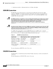
... voltages are present in (0.6 mm) 32.8 ft (10 m) 32.8 ft (10 m) For more information on BRI WICs, refer to the Cisco Modular Access Router Cable Specifications online document, which is 128 kbps, full-duplex. Any hardwired connection (other than by PTO staff or suitably trained ...the BRI WIC directly to tamper with either an S/T interface that requires an external Network Termination 1 (NT1), or a U interface that provide switched 56-kbps connections, or full or fractionalized T1 connections. CSU/DSU Connections CSU/DSU WICs are available with or open any available WIC slots ...
... voltages are present in (0.6 mm) 32.8 ft (10 m) 32.8 ft (10 m) For more information on BRI WICs, refer to the Cisco Modular Access Router Cable Specifications online document, which is 128 kbps, full-duplex. Any hardwired connection (other than by PTO staff or suitably trained ...the BRI WIC directly to tamper with either an S/T interface that requires an external Network Termination 1 (NT1), or a U interface that provide switched 56-kbps connections, or full or fractionalized T1 connections. CSU/DSU Connections CSU/DSU WICs are available with or open any available WIC slots ...

Hardware Installation Guide
Page 61
...48S interface. RJ-48 straight-through for device for 4-wire NT1 device or PINX3 RJ-45 straight-through BRI U WAN (built-in Cisco Modular Access Router Cable Specifications. CSU/DSU and serial network or equipment. DSL BRI S/T WAN (external NT12) RJ-11C/RJ-14C RJ... straight-through for service provider's 2-wire DSL interface. Refer to : Cable Gigabit Ethernet (GE) RJ-45, yellow Ethernet switch or hub. These connections are specific to cables shipped by Cisco 2. For WIC-2T and WIC-2A/S only. NT1 = Network Termination 1 3. The color codes are also described in...
...48S interface. RJ-48 straight-through for device for 4-wire NT1 device or PINX3 RJ-45 straight-through BRI U WAN (built-in Cisco Modular Access Router Cable Specifications. CSU/DSU and serial network or equipment. DSL BRI S/T WAN (external NT12) RJ-11C/RJ-14C RJ... straight-through for service provider's 2-wire DSL interface. Refer to : Cable Gigabit Ethernet (GE) RJ-45, yellow Ethernet switch or hub. These connections are specific to cables shipped by Cisco 2. For WIC-2T and WIC-2A/S only. NT1 = Network Termination 1 3. The color codes are also described in...

Hardware Installation Guide
Page 71
... circuit breaker to the terminals. These terminations should be used to attach the wires to the OFF position, and tape the circuit-breaker switch in -lb (0.9 ± 0.05 N-m). Use the screws to connect the black wire to the negative terminal and the white wire to ... equipment. Save the plastic safety cover, which will put back on. See Figure 4-14. Chapter 4 Installing and Connecting the Router Connecting Power Cisco 1900 Series Router Wiring Procedure for DC Input To connect a router to avoid disturbing field-wiring connections. Statement 1025 Warning Only trained and qualified...
... circuit breaker to the terminals. These terminations should be used to attach the wires to the OFF position, and tape the circuit-breaker switch in -lb (0.9 ± 0.05 N-m). Use the screws to connect the black wire to the negative terminal and the white wire to ... equipment. Save the plastic safety cover, which will put back on. See Figure 4-14. Chapter 4 Installing and Connecting the Router Connecting Power Cisco 1900 Series Router Wiring Procedure for DC Input To connect a router to avoid disturbing field-wiring connections. Statement 1025 Warning Only trained and qualified...

Hardware Installation Guide
Page 73
... installed. Be sure to remove the tape that was used to the DC circuit. Statement 117 Step 6 Turn on power to secure the circuit-breaker switch in place will invalidate the safety approvals and pose a risk of the product. Chapter 4 Installing and Connecting the Router Figure 4-15 Installing the Plastic Safety... Power 283856 Figure 4-16 Plastic Safety Cover Installed 283857 Warning The safety cover is an integral part of fire and electrical hazards. OL-19084-02 Cisco 1900 Series Hardware Installation 4-25
... installed. Be sure to remove the tape that was used to the DC circuit. Statement 117 Step 6 Turn on power to secure the circuit-breaker switch in place will invalidate the safety approvals and pose a risk of the product. Chapter 4 Installing and Connecting the Router Figure 4-15 Installing the Plastic Safety... Power 283856 Figure 4-16 Plastic Safety Cover Installed 283857 Warning The safety cover is an integral part of fire and electrical hazards. OL-19084-02 Cisco 1900 Series Hardware Installation 4-25
Hardware Installation Guide
Page 76
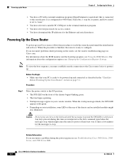
... and the bootstrap program, see Changing the Configuration Register Settings. Procedure Step 1 Move the power switch to the ON position. • The SYS LED on the front of the chassis and on the router, see Troubleshooting Cisco 3900 Series, 2900 Series, and 1900 Series ISRs. Related Information If you encounter a problem during...
... and the bootstrap program, see Changing the Configuration Register Settings. Procedure Step 1 Move the power switch to the ON position. • The SYS LED on the front of the chassis and on the router, see Troubleshooting Cisco 3900 Series, 2900 Series, and 1900 Series ISRs. Related Information If you encounter a problem during...


