
Hardware Installation Guide
Page 2
.... Changing the Way We Work, Live, Play, and Learn, Cisco Store, and Flip Gift Card are trademarks; IF YOU ARE UNABLE TO LOCATE THE SOFTWARE LICENSE OR LIMITED WARRANTY, CONTACT YOUR CISCO REPRESENTATIVE FOR A COPY. Operation of California. If it was probably caused by the University of California, Berkeley (UCB) as part of UCB's public domain version of its peripheral devices...
.... Changing the Way We Work, Live, Play, and Learn, Cisco Store, and Flip Gift Card are trademarks; IF YOU ARE UNABLE TO LOCATE THE SOFTWARE LICENSE OR LIMITED WARRANTY, CONTACT YOUR CISCO REPRESENTATIVE FOR A COPY. Operation of California. If it was probably caused by the University of California, Berkeley (UCB) as part of UCB's public domain version of its peripheral devices...

Hardware Installation Guide
Page 5
... Hardware Features 1-2 Front Panel Controls and LEDs 1-2 Location of Ports and Connectors 1-3 Preparing to Install the Wide Area Virtualization Engine 2-1 Safety Warnings 2-1 Safety Guidelines 2-4 General Precautions 2-4 System Reliability Considerations 2-6 Protecting Against Electrostatic Discharge 2-7 Installing the Wide Area Virtualization Engine 3-1 Installing the WAVE Appliance on a Tabletop 3-2 Installing the WAVE Appliance on a Wall 3-2 Installing the WAVE Appliance in an Equipment Rack 3-5 Rack-Mounting Considerations 3-5 Rack Requirements 3-6 Rack Installation 3-6 Connecting Cables...
... Hardware Features 1-2 Front Panel Controls and LEDs 1-2 Location of Ports and Connectors 1-3 Preparing to Install the Wide Area Virtualization Engine 2-1 Safety Warnings 2-1 Safety Guidelines 2-4 General Precautions 2-4 System Reliability Considerations 2-6 Protecting Against Electrostatic Discharge 2-7 Installing the Wide Area Virtualization Engine 3-1 Installing the WAVE Appliance on a Tabletop 3-2 Installing the WAVE Appliance on a Wall 3-2 Installing the WAVE Appliance in an Equipment Rack 3-5 Rack-Mounting Considerations 3-5 Rack Requirements 3-6 Rack Installation 3-6 Connecting Cables...
Hardware Installation Guide
Page 6
... Checking Connections and Switches 5-3 Troubleshooting the Ethernet Controller 5-4 Network Connection Problems 5-4 Ethernet Controller Troubleshooting Chart 5-5 Undetermined Problems 5-6 Problem-Solving Tips 5-7 Symptoms and Solutions 5-8 Power-On Self Test (POST) 5-12 POST Overview 5-12 POST Numeric Codes and Text Messages 5-13 Interpreting POST Diagnostic Front Panel LEDs and Beep Codes 5-16 Wide Area Virtualization Engine Hardware Specifications A-1 Appliance Specifications A-1 Inline Adapter Specifications A-4 Cisco Wide Area Virtualization Engine 274 and 474 Hardware Installation Guide...
... Checking Connections and Switches 5-3 Troubleshooting the Ethernet Controller 5-4 Network Connection Problems 5-4 Ethernet Controller Troubleshooting Chart 5-5 Undetermined Problems 5-6 Problem-Solving Tips 5-7 Symptoms and Solutions 5-8 Power-On Self Test (POST) 5-12 POST Overview 5-12 POST Numeric Codes and Text Messages 5-13 Interpreting POST Diagnostic Front Panel LEDs and Beep Codes 5-16 Wide Area Virtualization Engine Hardware Specifications A-1 Appliance Specifications A-1 Inline Adapter Specifications A-4 Cisco Wide Area Virtualization Engine 274 and 474 Hardware Installation Guide...
Hardware Installation Guide
Page 23
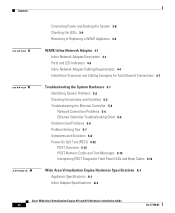
... Virtualization Engine Hardware Features The power control button powers up and powers down the system. Table 1-1 LED Power-on page 5-1. CD/DVD drive is in normal operation, use the serial console port. Hard disk drive is in use . Note You can connect a keyboard to any USB port and connect a monitor to the video connector to troubleshoot the BIOS boot process. To monitor the boot process in use . Location of Ports and Connectors The WAVE-274 and WAVE-474 appliances support one Ethernet port and one console port. However, video output is displaying a diagnostic code...
... Virtualization Engine Hardware Features The power control button powers up and powers down the system. Table 1-1 LED Power-on page 5-1. CD/DVD drive is in normal operation, use the serial console port. Hard disk drive is in use . Note You can connect a keyboard to any USB port and connect a monitor to the video connector to troubleshoot the BIOS boot process. To monitor the boot process in use . Location of Ports and Connectors The WAVE-274 and WAVE-474 appliances support one Ethernet port and one console port. However, video output is displaying a diagnostic code...

Hardware Installation Guide
Page 24
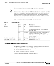
... Virtualization Engine 274 and 474 Hardware Installation Guide 1-4 OL-17739-01 Some LAN and WAN ports both use RJ-45 connectors. The keyboard and monitor are used to telephone-network voltage (TNV) circuits. Use caution when connecting cables. After the BIOS boots, all input and output for troubleshooting purposes. Statement 1021 Figure 1-2 shows the location of the serial console port. Figure 1-2 Back Panel LEDs and Connectors 1 PS/2 mouse port (unused) 2 PS/2 keyboard port (unused) 3 Console port (RS232 serial COM1 port) 4 VGA port (unused) 5 4 USB ports...
... Virtualization Engine 274 and 474 Hardware Installation Guide 1-4 OL-17739-01 Some LAN and WAN ports both use RJ-45 connectors. The keyboard and monitor are used to telephone-network voltage (TNV) circuits. Use caution when connecting cables. After the BIOS boots, all input and output for troubleshooting purposes. Statement 1021 Figure 1-2 shows the location of the serial console port. Figure 1-2 Back Panel LEDs and Connectors 1 PS/2 mouse port (unused) 2 PS/2 keyboard port (unused) 3 Console port (RS232 serial COM1 port) 4 VGA port (unused) 5 4 USB ports...
Hardware Installation Guide
Page 25
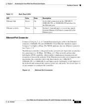
... On Description Active link connection on the system board. Figure 1-3 Ethernet Port Connector OL-17739-01 Cisco Wide Area Virtualization Engine 274 and 474 Hardware Installation Guide 1-5 System is connected to or receiving signals from the Ethernet LAN that rate and mode. Ethernet Port Connector Connect a Category 3, 4, or 5 unshielded twisted-pair cable to set any jumpers or configure the controller. If the Ethernet port in the server supports auto negotiation, the controllers detect the data-transfer rate (10BASE...
... On Description Active link connection on the system board. Figure 1-3 Ethernet Port Connector OL-17739-01 Cisco Wide Area Virtualization Engine 274 and 474 Hardware Installation Guide 1-5 System is connected to or receiving signals from the Ethernet LAN that rate and mode. Ethernet Port Connector Connect a Category 3, 4, or 5 unshielded twisted-pair cable to set any jumpers or configure the controller. If the Ethernet port in the server supports auto negotiation, the controllers detect the data-transfer rate (10BASE...

Hardware Installation Guide
Page 32
... enable the cooling system to Install the Wide Area Virtualization Engine • Observe power strip ratings. See the documentation that comes with the adapters. • A failed fan is replaced within 2 minutes of the drive bays has either a drive or a filler panel installed. • For rack configurations, make sure that the following occurs: • Each of removal. • Cables for optional adapters are disconnected before you open the air baffle cover...
... enable the cooling system to Install the Wide Area Virtualization Engine • Observe power strip ratings. See the documentation that comes with the adapters. • A failed fan is replaced within 2 minutes of the drive bays has either a drive or a filler panel installed. • For rack configurations, make sure that the following occurs: • Each of removal. • Cables for optional adapters are disconnected before you open the air baffle cover...

Hardware Installation Guide
Page 39
... space provides proper airflow. • Plan the device installation starting from the bottom of the rack at the same time. • Remove the rack doors and side panels to provide easier access during installation. • Connect the WAVE appliance to install your WAVE appliance in a rack, review the following topics: • Rack-Mounting Considerations, page 3-5 • Rack Requirements, page 3-6 • Rack Installation, page 3-6 Rack-Mounting Considerations Before installing your WAVE-274 or WAVE-474 in an equipment...
... space provides proper airflow. • Plan the device installation starting from the bottom of the rack at the same time. • Remove the rack doors and side panels to provide easier access during installation. • Connect the WAVE appliance to install your WAVE appliance in a rack, review the following topics: • Rack-Mounting Considerations, page 3-5 • Rack Requirements, page 3-6 • Rack Installation, page 3-6 Rack-Mounting Considerations Before installing your WAVE-274 or WAVE-474 in an equipment...

Hardware Installation Guide
Page 48
... straight-through Crossover or straight-through Crossover or straight-through . When you are connecting a WAVE inline appliance between two devices using Gigabit Ethernet end to autonegotiate link speeds. Note You must retain the same link speed from one end of cables: crossover and straight-through Cisco Wide Area Virtualization Engine 274 and 474 Hardware Installation Guide 4-4 OL-17739-01 Speed and duplex settings are able to end.
... straight-through Crossover or straight-through Crossover or straight-through . When you are connecting a WAVE inline appliance between two devices using Gigabit Ethernet end to autonegotiate link speeds. Note You must retain the same link speed from one end of cables: crossover and straight-through Cisco Wide Area Virtualization Engine 274 and 474 Hardware Installation Guide 4-4 OL-17739-01 Speed and duplex settings are able to end.

Hardware Installation Guide
Page 56
... the console connection.) You can run all external devices. Cisco Wide Area Virtualization Engine 274 and 474 Hardware Installation Guide 5-2 OL-17739-01 When console redirection is enabled, all the tests available from a keyboard are accessible through the console connection as the systems-management Ethernet connector and the SAS connector) that are not supported by the WAAS software are invalid. Power up the device. If necessary, see the "Undetermined Problems" section on self-test (POST) and the diagnostic...
... the console connection.) You can run all external devices. Cisco Wide Area Virtualization Engine 274 and 474 Hardware Installation Guide 5-2 OL-17739-01 When console redirection is enabled, all the tests available from a keyboard are accessible through the console connection as the systems-management Ethernet connector and the SAS connector) that are not supported by the WAAS software are invalid. Power up the device. If necessary, see the "Undetermined Problems" section on self-test (POST) and the diagnostic...
Hardware Installation Guide
Page 57
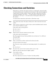
... system. Yes. OL-17739-01 Cisco Wide Area Virtualization Engine 274 and 474 Hardware Installation Guide 5-3 Yes. The original electrical outlet probably does not function. Plug a system that all the power cables from their electrical outlets. Is the problem resolved? You have fixed the problem. Is the power strip receiving power? Go to Step 5. No. The power strip is connected to Step 5. Reconnect the...
... system. Yes. OL-17739-01 Cisco Wide Area Virtualization Engine 274 and 474 Hardware Installation Guide 5-3 Yes. The original electrical outlet probably does not function. Plug a system that all the power cables from their electrical outlets. Is the problem resolved? You have fixed the problem. Is the power strip receiving power? Go to Step 5. No. The power strip is connected to Step 5. Reconnect the...

Hardware Installation Guide
Page 58
... the connector, cable, or switch: Cisco Wide Area Virtualization Engine 274 and 474 Hardware Installation Guide 5-4 OL-17739-01 This section contains the following topics: • Network Connection Problems, page 5-4 • Ethernet Controller Troubleshooting Chart, page 5-5 Network Connection Problems If the Ethernet controller cannot connect to operate at all connections. If the cable is attached but the problem remains, try configuring the integrated Ethernet controller manually to which the WAVE appliance is installed correctly. Troubleshooting the Ethernet Controller Chapter...
... the connector, cable, or switch: Cisco Wide Area Virtualization Engine 274 and 474 Hardware Installation Guide 5-4 OL-17739-01 This section contains the following topics: • Network Connection Problems, page 5-4 • Ethernet Controller Troubleshooting Chart, page 5-5 Network Connection Problems If the Ethernet controller cannot connect to operate at all connections. If the cable is attached but the problem remains, try configuring the integrated Ethernet controller manually to which the WAVE appliance is installed correctly. Troubleshooting the Ethernet Controller Chapter...
Hardware Installation Guide
Page 61
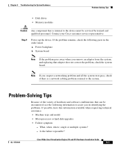
... suspect a networking problem and all the system tests pass, check if there is internal to the system. OL-17739-01 Cisco Wide Area Virtualization Engine 274 and 474 Hardware Installation Guide 5-7 single or multiple systems? - Power backplane b. Step 4 Power up the device. Note If you in the order listed: a. Contact your Cisco customer service representative. Chapter 5 Troubleshooting the System Hardware Problem-Solving Tips • Disk drives • Memory modules Caution Any component that is a network cabling problem external...
... suspect a networking problem and all the system tests pass, check if there is internal to the system. OL-17739-01 Cisco Wide Area Virtualization Engine 274 and 474 Hardware Installation Guide 5-7 single or multiple systems? - Power backplane b. Step 4 Power up the device. Note If you in the order listed: a. Contact your Cisco customer service representative. Chapter 5 Troubleshooting the System Hardware Problem-Solving Tips • Disk drives • Memory modules Caution Any component that is a network cabling problem external...

Hardware Installation Guide
Page 63
...-RW/DVD drive. The CD-RW/DVD drive tray is enabled in the configuration/setup utility program. Verify the following items: a. Insert the end of a straightened paper clip into the manual tray-release opening. 3. Make sure that the device is not 1. cover latch or indicator LEDs not working. Run the hard disk drive diagnostic tests again. b. The correct device driver is not recognized. 1. OL-17739-01 Cisco Wide Area Virtualization Engine 274 and 474 Hardware Installation Guide...
...-RW/DVD drive. The CD-RW/DVD drive tray is enabled in the configuration/setup utility program. Verify the following items: a. Insert the end of a straightened paper clip into the manual tray-release opening. 3. Make sure that the device is not 1. cover latch or indicator LEDs not working. Run the hard disk drive diagnostic tests again. b. The correct device driver is not recognized. 1. OL-17739-01 Cisco Wide Area Virtualization Engine 274 and 474 Hardware Installation Guide...
Hardware Installation Guide
Page 65
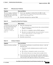
... microprocessor is connected only to use the software. The device is designed to the correct port (see the "Interpreting POST Diagnostic Front Panel LEDs and Beep Codes" section on page 5-16). 2. Cause and Action 1. b. The software is compatible with the software for a failing serial device. 3. OL-17739-01 Cisco Wide Area Virtualization Engine 274 and 474 Hardware Installation Guide 5-11 The software that comes with the WAVE appliance. Table 5-8 Console Port (Serial Port) Problems Symptom FRU or Action A serial device does...
... microprocessor is connected only to use the software. The device is designed to the correct port (see the "Interpreting POST Diagnostic Front Panel LEDs and Beep Codes" section on page 5-16). 2. Cause and Action 1. b. The software is compatible with the software for a failing serial device. 3. OL-17739-01 Cisco Wide Area Virtualization Engine 274 and 474 Hardware Installation Guide 5-11 The software that comes with the WAVE appliance. Table 5-8 Console Port (Serial Port) Problems Symptom FRU or Action A serial device does...

Hardware Installation Guide
Page 68
... Power-On Self Test (POST) Chapter 5 Troubleshooting the System Hardware Table 5-10 Diagnostic Front Panel LEDs and Beep Codes (continued) Control Panel Message Description 201-Memory Error RAM failure. 213-Incompatible Memory Module in the error message is missing critical SPD information or is incompatible with the chip set. 214-DIMM Configuration Warning Populated DIMM configuration is not optimized. 219-ECC Memory Module Detected ECC Modules not supported on this Platform Recently added memory module(s) support ECC memory error correction. 301-Keyboard Error Keyboard failure...
... Power-On Self Test (POST) Chapter 5 Troubleshooting the System Hardware Table 5-10 Diagnostic Front Panel LEDs and Beep Codes (continued) Control Panel Message Description 201-Memory Error RAM failure. 213-Incompatible Memory Module in the error message is missing critical SPD information or is incompatible with the chip set. 214-DIMM Configuration Warning Populated DIMM configuration is not optimized. 219-ECC Memory Module Detected ECC Modules not supported on this Platform Recently added memory module(s) support ECC memory error correction. 301-Keyboard Error Keyboard failure...

Hardware Installation Guide
Page 69
... is configured for RAID mode. 1801-Microcode Patch Error Processor is not supported by ROM BIOS. 2216-Powered USB cable not attached Powered USB cable is not properly attached to the USB PlusPower expansion card or to fail. (Some hard drives have a hard drive firmware patch that will fix an erroneous error message.) 1796-SATA Cabling Error One or more SATA devices are assigned to the same IRQ. 1201-System Audio Address Conflict Detected Device IRQ address conflicts with another device. 1202-MIDI Port Address Conflict Detected Device IRQ address...
... is configured for RAID mode. 1801-Microcode Patch Error Processor is not supported by ROM BIOS. 2216-Powered USB cable not attached Powered USB cable is not properly attached to the USB PlusPower expansion card or to fail. (Some hard drives have a hard drive firmware patch that will fix an erroneous error message.) 1796-SATA Cabling Error One or more SATA devices are assigned to the same IRQ. 1201-System Audio Address Conflict Detected Device IRQ address conflicts with another device. 1202-MIDI Port Address Conflict Detected Device IRQ address...

Hardware Installation Guide
Page 70
... required. Once you have an error code or text message associated with them. None Computer in which they should be replaced by a qualified service technician. Press any key or move the mouse to RAM mode (some models only) or normal Suspend mode. Power-On Self Test (POST) Chapter 5 Troubleshooting the System Hardware Table 5-10 Diagnostic Front Panel LEDs and Beep Codes (continued) Control Panel Message Description Network Server Mode Active and No Keyboard Keyboard failure while Network Server Mode Attached enabled...
... required. Once you have an error code or text message associated with them. None Computer in which they should be replaced by a qualified service technician. Press any key or move the mouse to RAM mode (some models only) or normal Suspend mode. Power-On Self Test (POST) Chapter 5 Troubleshooting the System Hardware Table 5-10 Diagnostic Front Panel LEDs and Beep Codes (continued) Control Panel Message Description Network Server Mode Active and No Keyboard Keyboard failure while Network Server Mode Attached enabled...

Hardware Installation Guide
Page 72
..., install, or remove a DIMM module. 1. Pre-video memory error. CAUTION: To avoid damage to the DIMMs or the system board, you must unplug the computer power cord before attempting to ensure that is solved. Beeps stop after fifth iteration but LEDs continue until problem is solved. Replace the device that all attached devices such as hard drives, optical drives, and expansion cards. Power-On Self Test (POST) Chapter 5 Troubleshooting the System Hardware Table 5-11 POST Diagnostic Front Panel LEDs and Beep Codes...
..., install, or remove a DIMM module. 1. Pre-video memory error. CAUTION: To avoid damage to the DIMMs or the system board, you must unplug the computer power cord before attempting to ensure that is solved. Beeps stop after fifth iteration but LEDs continue until problem is solved. Replace the device that all attached devices such as hard drives, optical drives, and expansion cards. Power-On Self Test (POST) Chapter 5 Troubleshooting the System Hardware Table 5-11 POST Diagnostic Front Panel LEDs and Beep Codes...
Hardware Installation Guide
Page 76
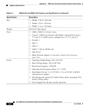
...; Power Supply Fan: 80 mm variable speed fan Cisco Wide Area Virtualization Engine 274 and 474 Hardware Installation Guide A-2 OL-17739-01 Appliance Specifications Appendix A Wide Area Virtualization Engine Hardware Specifications Table A-1 WAVE-274 and WAVE-474 Features and Specifications (continued) Specification Size Weight Ports Power Description • Height: 3.94 in. (10.0 cm) • Depth: 15.0 in. (38.0 cm) • Width: 13.4 in and line out • NIC: RJ-45 • Inline Network Adapter: 2 (see Inline Adapter Specifications...
...; Power Supply Fan: 80 mm variable speed fan Cisco Wide Area Virtualization Engine 274 and 474 Hardware Installation Guide A-2 OL-17739-01 Appliance Specifications Appendix A Wide Area Virtualization Engine Hardware Specifications Table A-1 WAVE-274 and WAVE-474 Features and Specifications (continued) Specification Size Weight Ports Power Description • Height: 3.94 in. (10.0 cm) • Depth: 15.0 in. (38.0 cm) • Width: 13.4 in and line out • NIC: RJ-45 • Inline Network Adapter: 2 (see Inline Adapter Specifications...


